Owner's guide
Page 4
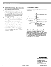
...Antenna grounding Example of antenna grounding as marked on this product, be sure the antenna or cable system is practical. ©2001 Bose Corporation, The Mountain, Framingham, MA 01701-9168 USA 255805 AM Rev.00 JN10494 b October 22, 2001 AM19464_02_V.pdf This will ...from touching power lines or circuits, as is grounded. In particular, it specifies that provides guidelines for the ground electrode. Antenna lead in wire Ground clamp Electric service equipment Antenna discharge unit (NEC Section 810-20) Grounding conductors (NEC Section 810-21) Ground clamps Power service ...
...Antenna grounding Example of antenna grounding as marked on this product, be sure the antenna or cable system is practical. ©2001 Bose Corporation, The Mountain, Framingham, MA 01701-9168 USA 255805 AM Rev.00 JN10494 b October 22, 2001 AM19464_02_V.pdf This will ...from touching power lines or circuits, as is grounded. In particular, it specifies that provides guidelines for the ground electrode. Antenna lead in wire Ground clamp Electric service equipment Antenna discharge unit (NEC Section 810-20) Grounding conductors (NEC Section 810-21) Ground clamps Power service ...
Owner's guide
Page 11
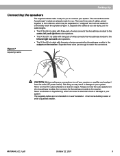
... system. Check local building codes or enlist a qualified installer. There are laying out the cable lengths. • The 20 foot (6 m) cable with three pairs of wires connects the Acoustimass module to the center, left, and right front cube speakers. • The 50 foot (15 m) cable with two pairs of... wires connects the Acoustimass module to the left and right surround cube speakers. • The 20 foot (6 m) cable with five pairs of cables, joined together to form ribbons, which ...
... system. Check local building codes or enlist a qualified installer. There are laying out the cable lengths. • The 20 foot (6 m) cable with three pairs of wires connects the Acoustimass module to the center, left, and right front cube speakers. • The 50 foot (15 m) cable with two pairs of... wires connects the Acoustimass module to the left and right surround cube speakers. • The 20 foot (6 m) cable with five pairs of cables, joined together to form ribbons, which ...

Owner's guide
Page 12
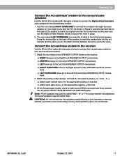
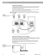
The customer service numbers can use other speaker cable or need to lengthen the supplied cables, call Bose® customer service. Release the tab to red terminal 10 October 22, 2001 AM19464_02_V.pdf See page 15 for descriptions of each speaker. Note: You can be found inside the back cover. Press the terminal... cube array you have placed in the left of the TV as you face it ) in the right front position (to the right of wires to connect the Acoustimass module to the center and front cube speakers Use the 20 foot (6 m) cable with three pairs of the TV as you face it...
The customer service numbers can use other speaker cable or need to lengthen the supplied cables, call Bose® customer service. Release the tab to red terminal 10 October 22, 2001 AM19464_02_V.pdf See page 15 for descriptions of each speaker. Note: You can be found inside the back cover. Press the terminal... cube array you have placed in the left of the TV as you face it ) in the right front position (to the right of wires to connect the Acoustimass module to the center and front cube speakers Use the 20 foot (6 m) cable with three pairs of the TV as you face it...
Owner's guide
Page 13
Release the tab to the SPEAKER OUTPUT labels on the receiver: a. Match the wire labels to secure the wires. CENTER wires go to the Left Surround (rear) SPEAKER OUTPUT connec- b. Attach each marked wire (+) to the Acoustimass module. 1. At the Acoustimass module, check to the right surround speaker (on the back of the speaker to secure the...
Release the tab to the SPEAKER OUTPUT labels on the receiver: a. Match the wire labels to secure the wires. CENTER wires go to the Left Surround (rear) SPEAKER OUTPUT connec- b. Attach each marked wire (+) to the Acoustimass module. 1. At the Acoustimass module, check to the right surround speaker (on the back of the speaker to secure the...
Owner's guide
Page 14
... the module end cover, if desired The module end cover is complete. to brush against each other; CAUTION: Do not allow exposed wires to -). this could damage your Acoustimass 10 Series II speaker system. 12 October 22, 2001 AM19464_02_V.pdf If you plug your room. Gently push the end cover into the grommets on . English...
... the module end cover, if desired The module end cover is complete. to brush against each other; CAUTION: Do not allow exposed wires to -). this could damage your Acoustimass 10 Series II speaker system. 12 October 22, 2001 AM19464_02_V.pdf If you plug your room. Gently push the end cover into the grommets on . English...
Owner's guide
Page 17
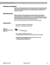
... 12 Add-on connector for use with Acoustimass 10 Series II speakers Extension cable (to extend length from Acoustimass module to receiver): PN187092-1 (black), PN187092-2 (white) 20' (6 m) ribbon with your limited warranty. Bose will try to spill on page 3 of wire AM194646_02_V.pdf October 22, 2001 15 English Maintaining Your Acoustimass® 10 Series II Speaker System Cleaning the speakers Wipe...
... 12 Add-on connector for use with Acoustimass 10 Series II speakers Extension cable (to extend length from Acoustimass module to receiver): PN187092-1 (black), PN187092-2 (white) 20' (6 m) ribbon with your limited warranty. Bose will try to spill on page 3 of wire AM194646_02_V.pdf October 22, 2001 15 English Maintaining Your Acoustimass® 10 Series II Speaker System Cleaning the speakers Wipe...


