
U8668 Pro user's manual
Page 1
This equipment generates, uses and can radiate radio frequency energy and, if not installed and used in accordance with the limits of a Class B digital device, pursuant to radio communications. Duplication of merchantability or fitness for any mistakes found to comply with the instructions, may cause harmful interference to Part 15 of the FCC Rules. All the brand and product names are designed to be changed without notice and we will not occur in a particular installation. There is no representations or warranties with respect to the contents here of and specially disclaims any ...
This equipment generates, uses and can radiate radio frequency energy and, if not installed and used in accordance with the limits of a Class B digital device, pursuant to radio communications. Duplication of merchantability or fitness for any mistakes found to comply with the instructions, may cause harmful interference to Part 15 of the FCC Rules. All the brand and product names are designed to be changed without notice and we will not occur in a particular installation. There is no representations or warranties with respect to the contents here of and specially disclaims any ...

U8668 Pro user's manual
Page 2
... LAN Header: JWOL1 16 4-6. Package Contents 6 2. CPU Fan Header: JCFAN1 11 3-3. ATX 20-pin Power Connector: JATXPWR1 15 4-3. Front USB Header: JUSB3 17 4-8. Table of U8668 Pro 7 2-2. Hardware...2 1-2. Mainboard Configuration 7 2-1. BIOS & Software 6 1-3. Layout of Contents Notice 1 Mainboard Features 2 1. Component Index 8 3. Jumpers, Headers & Connectors 12 4-1.
... LAN Header: JWOL1 16 4-6. Package Contents 6 2. CPU Fan Header: JCFAN1 11 3-3. ATX 20-pin Power Connector: JATXPWR1 15 4-3. Front USB Header: JUSB3 17 4-8. Table of U8668 Pro 7 2-2. Hardware...2 1-2. Mainboard Configuration 7 2-1. BIOS & Software 6 1-3. Layout of Contents Notice 1 Mainboard Features 2 1. Component Index 8 3. Jumpers, Headers & Connectors 12 4-1.

U8668 Pro user's manual
Page 3
DDR SDRAM 19 5-2 SDRAM...20 5-3. PS/2 Mouse / Keyboard Connector: JKBMS1 23 6-2. Audio Port Connectors: JSPKR1/JLIN1/JMIC1 29 6-6. How to install DDR/SDRAM DIMM Module 21 6. Peripheral Port Features 23 6-1. USB & LAN Port Connectors: JUSBLAN1 24 6-3. Game (Joystick/MIDI) Port Connector: JAUD_GAME 29 6-5. RAM Module Configuration 19 5-1. Serial and Parallel Interface Ports 26 6-4. Audio Subsystem 30 ii Table of Contents 4-10. ATX 12V Power Connector: JATXPWR2 18 4-11. 5V / 5VSB Selection for USB: JUSBV3 18 4-12. 5V / 5VSB Selection for USB: JUSBV4 18 5.
DDR SDRAM 19 5-2 SDRAM...20 5-3. PS/2 Mouse / Keyboard Connector: JKBMS1 23 6-2. Audio Port Connectors: JSPKR1/JLIN1/JMIC1 29 6-6. How to install DDR/SDRAM DIMM Module 21 6. Peripheral Port Features 23 6-1. USB & LAN Port Connectors: JUSBLAN1 24 6-3. Game (Joystick/MIDI) Port Connector: JAUD_GAME 29 6-5. RAM Module Configuration 19 5-1. Serial and Parallel Interface Ports 26 6-4. Audio Subsystem 30 ii Table of Contents 4-10. ATX 12V Power Connector: JATXPWR2 18 4-11. 5V / 5VSB Selection for USB: JUSBV3 18 4-12. 5V / 5VSB Selection for USB: JUSBV4 18 5.
U8668 Pro user's manual
Page 4
U8668 Pro Features: 1.Contains on board I/O facilities that include a serial port, a VGA port, a parallel port, a PS/2 mouse port, a PS/2 keyboard port, audio ports, USB ports and a game ...
U8668 Pro Features: 1.Contains on board I/O facilities that include a serial port, a VGA port, a parallel port, a PS/2 mouse port, a PS/2 keyboard port, audio ports, USB ports and a game ...
U8668 Pro user's manual
Page 5
Speed: 1.Runing at 400 MHz Front Side Bus frequency. 2.Supports up to 2.4 GHz CPU core speeds. 3.The 33MHz 32 bit PCI 2.2 compliant. 4.The 66MHz AGP 2.0 compliant interface supports 1x, 2x and 4x data transfer mode. VIA VT8751 (P4M266)/ VT8235. Hardware CPU: 1.Provides Socket-478. 2.Supports the Intel Pentium ® 4 processor providing the new generation power for x8 and 16 devices. 3.The largest memory capacity is 2 GB. 2 Chipset: Chipset - Chapter 1 Motherboard Description Mainboard Features 1. Super I/O Chipset - Features Introduction 1-1. ITE 8705 DRAM Memory: 1.Supports ...
Speed: 1.Runing at 400 MHz Front Side Bus frequency. 2.Supports up to 2.4 GHz CPU core speeds. 3.The 33MHz 32 bit PCI 2.2 compliant. 4.The 66MHz AGP 2.0 compliant interface supports 1x, 2x and 4x data transfer mode. VIA VT8751 (P4M266)/ VT8235. Hardware CPU: 1.Provides Socket-478. 2.Supports the Intel Pentium ® 4 processor providing the new generation power for x8 and 16 devices. 3.The largest memory capacity is 2 GB. 2 Chipset: Chipset - Chapter 1 Motherboard Description Mainboard Features 1. Super I/O Chipset - Features Introduction 1-1. ITE 8705 DRAM Memory: 1.Supports ...

U8668 Pro user's manual
Page 6
Contains 3 32-bit PCI bus slots Fast EtherNet 10/ 100 1-Port PHY/ Transceiver: 1.Dual Speed - 100/ 10 Mbps. 2.Half and Full Duplex. 3.MII Interface to 15 minutes. Flash Memory: 1.Supports flash memory functionality. 2.Supports ESCD functionality. Chapter 1 Motherboard Description Shadow RAM: Motherboard is equipped with Monitor Power 3 BUS Slots: 1.Contains 1 AGP slot. 2.Contains 1 CNR slot. 3. Built in VGA: 1. Green Functionality: 1.Supports Award BIOS ™ power management functionality. 2.Has a power down timer from 1 to Ethernet Controller. 4.Optional Repeater Interface...
Contains 3 32-bit PCI bus slots Fast EtherNet 10/ 100 1-Port PHY/ Transceiver: 1.Dual Speed - 100/ 10 Mbps. 2.Half and Full Duplex. 3.MII Interface to 15 minutes. Flash Memory: 1.Supports flash memory functionality. 2.Supports ESCD functionality. Chapter 1 Motherboard Description Shadow RAM: Motherboard is equipped with Monitor Power 3 BUS Slots: 1.Contains 1 AGP slot. 2.Contains 1 CNR slot. 3. Built in VGA: 1. Green Functionality: 1.Supports Award BIOS ™ power management functionality. 2.Has a power down timer from 1 to Ethernet Controller. 4.Optional Repeater Interface...

U8668 Pro user's manual
Page 7
Chapter 1 Motherboard Description Management protocols. 3.I2C Serial Bus for DDC Monitor Communications. 2. 2D Hardware Acceleration Features 1. Microsoft Direct X texture compression. 9. Anisotropic filtering. 3. 8-bit stencil buffer. 4. 32-bit true color rendering. 5. ROP3 Ternary Raster Operation BitBLTs. 2. 8, 16 and 32 bpp mode acceleration. 3. Floating-point triangle setup engine. 4. Full internal AGP 4x performance. 8. Specular lighting and diffuse shading. 6. Optimized Shared Memory Architecture (SMA). 2. 16 / 32 MB frame buffer using system memory. 3. High ...
Chapter 1 Motherboard Description Management protocols. 3.I2C Serial Bus for DDC Monitor Communications. 2. 2D Hardware Acceleration Features 1. Microsoft Direct X texture compression. 9. Anisotropic filtering. 3. 8-bit stencil buffer. 4. 32-bit true color rendering. 5. ROP3 Ternary Raster Operation BitBLTs. 2. 8, 16 and 32 bpp mode acceleration. 3. Floating-point triangle setup engine. 4. Full internal AGP 4x performance. 8. Specular lighting and diffuse shading. 6. Optimized Shared Memory Architecture (SMA). 2. 16 / 32 MB frame buffer using system memory. 3. High ...

U8668 Pro user's manual
Page 8
Universal Serial Bus: Supports two back panel Universal Serial Bus (USB2.0) Ports and four front panel Universal Serial Bus (USB2.0) Ports. Hardware Monitor Function: 1.Monitors CPU Fan Speed. 2.Monitors System Voltage. 3.Monitors System Speed. Motherboard Description AC'97 Sound Codec Onboard: 1.AC-LINK protocol comfliance. 2.Compliant with CD-ROM. 6.Supports high capacity hard disk drives. 7.Supports LBA mode. Dimensions (MATX form-factor): 24.5cm x 24.5cm (WxL) 5 I/O facilities: 1.One multi-mode Parallel Port capable of supporting the following specifications: Standard ...
Universal Serial Bus: Supports two back panel Universal Serial Bus (USB2.0) Ports and four front panel Universal Serial Bus (USB2.0) Ports. Hardware Monitor Function: 1.Monitors CPU Fan Speed. 2.Monitors System Voltage. 3.Monitors System Speed. Motherboard Description AC'97 Sound Codec Onboard: 1.AC-LINK protocol comfliance. 2.Compliant with CD-ROM. 6.Supports high capacity hard disk drives. 7.Supports LBA mode. Dimensions (MATX form-factor): 24.5cm x 24.5cm (WxL) 5 I/O facilities: 1.One multi-mode Parallel Port capable of supporting the following specifications: Standard ...

U8668 Pro user's manual
Page 9
Chapter 1 Motherboard Description 1-2. Operating System: Offers the highest performance for MATX Case (Optional). 6.Fully Setup Driver CD. 6 Package Contents 1.HDD Cable. 2.FDD Cable. 3.Flash Memory Writer for BIOS Update. 4.USB Cable (Optional). 5.Rear I/O Panel for MS-DOS, Windows NT, Windows 2000, Windows ME, Windows XP, Novell, LINUX, and SCO UNIX etc. 1-3. BIOS & Software 1.Award legal BIOS. 2.Supports APM1.2. 3.Supports USB Function. 4.Supports ACPI.
Chapter 1 Motherboard Description 1-2. Operating System: Offers the highest performance for MATX Case (Optional). 6.Fully Setup Driver CD. 6 Package Contents 1.HDD Cable. 2.FDD Cable. 3.Flash Memory Writer for BIOS Update. 4.USB Cable (Optional). 5.Rear I/O Panel for MS-DOS, Windows NT, Windows 2000, Windows ME, Windows XP, Novell, LINUX, and SCO UNIX etc. 1-3. BIOS & Software 1.Award legal BIOS. 2.Supports APM1.2. 3.Supports USB Function. 4.Supports ACPI.
U8668 Pro user's manual
Page 10
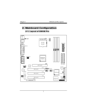
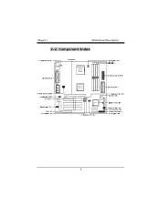
Mainboard Configuration 2-1. Layout of U8668 Pro JKBMS1 K/B & Mouse JUSBLAN USB & LAN JCOM1 JPRNT1 CPU1 Socket 478 CPU JATXPWR1 COM1 Parallel Port VGA1 PRIMARY IDE CONN. SECONDARY IDE CONN. LAN AGP SLOT IDE1 IDE2 PCI SLOT PCI SLOT PCI1 PCI2 JUSBV3 1 1 JUSBV4 2 10 2 10 1 91 9 JUSB3 JUSB4 B AT 1 VT8235 1 JCMOS1 FDD1 PCI3 PCI SLOT CNR1 CNR SLOT JWOL1 1 ITE I/O JPANEL1 2 24 1 23 7 Game Port In Out MIC Line Speaker JVGA1 JATXPWR2 P4M266 (VT8751) In Codec 1 JCDIN1 BIOS FLOPPY DISK CONN. Chapter 1 Motherboard Description 2.
Mainboard Configuration 2-1. Layout of U8668 Pro JKBMS1 K/B & Mouse JUSBLAN USB & LAN JCOM1 JPRNT1 CPU1 Socket 478 CPU JATXPWR1 COM1 Parallel Port VGA1 PRIMARY IDE CONN. SECONDARY IDE CONN. LAN AGP SLOT IDE1 IDE2 PCI SLOT PCI SLOT PCI1 PCI2 JUSBV3 1 1 JUSBV4 2 10 2 10 1 91 9 JUSB3 JUSB4 B AT 1 VT8235 1 JCMOS1 FDD1 PCI3 PCI SLOT CNR1 CNR SLOT JWOL1 1 ITE I/O JPANEL1 2 24 1 23 7 Game Port In Out MIC Line Speaker JVGA1 JATXPWR2 P4M266 (VT8751) In Codec 1 JCDIN1 BIOS FLOPPY DISK CONN. Chapter 1 Motherboard Description 2.
U8668 Pro user's manual
Page 11
Chapter 1 Motherboard Description 2-2. Component Index Socket 478 CPU BIOS Codec LAN P4M266 (VT8751) B AT1 VT8235 ITE I/O 8
Chapter 1 Motherboard Description 2-2. Component Index Socket 478 CPU BIOS Codec LAN P4M266 (VT8751) B AT1 VT8235 ITE I/O 8
U8668 Pro user's manual
Page 12
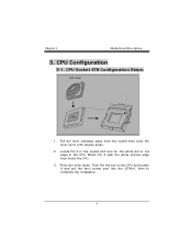
Match Pin A with the white dot/cut edge in the socket and look for the white dot or cut edge then insert the CPU. 3. Locate Pin A in the CPU. Then Put the fan on the CPU and buckle it and put the fan's power port into the JCFAN1, then to a 90-degree angle. 2. Chapter 1 Motherboard Description 3. CPU Socket 478 Configuration Steps: CPU Fan CPU 1. Pull the lever sideways away from the socket then raise the lever up to complete the installation. 9 CPU Configuration 3-1. Press the lever down.
Match Pin A with the white dot/cut edge in the socket and look for the white dot or cut edge then insert the CPU. 3. Locate Pin A in the CPU. Then Put the fan on the CPU and buckle it and put the fan's power port into the JCFAN1, then to a 90-degree angle. 2. Chapter 1 Motherboard Description 3. CPU Socket 478 Configuration Steps: CPU Fan CPU 1. Pull the lever sideways away from the socket then raise the lever up to complete the installation. 9 CPU Configuration 3-1. Press the lever down.
U8668 Pro user's manual
Page 13
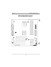
Chapter 1 Motherboard Description CPU Configuration Layout Socket 478 CPU BIOS Codec LAN P4M266 (VT8751) BAT1 VT8235 ITE I/O JSFAN1 10
Chapter 1 Motherboard Description CPU Configuration Layout Socket 478 CPU BIOS Codec LAN P4M266 (VT8751) BAT1 VT8235 ITE I/O JSFAN1 10
U8668 Pro user's manual
Page 14
Chapter 1 Motherboard Description 3-2. System Fan Header: JSFAN1 Pin No. 1 2 3 Assignment Ground +12V Sense 11 CPU Fan Header: JCFAN1 Pin No. 1 2 3 Assignment Ground +12V Sense 3-3.
Chapter 1 Motherboard Description 3-2. System Fan Header: JSFAN1 Pin No. 1 2 3 Assignment Ground +12V Sense 11 CPU Fan Header: JCFAN1 Pin No. 1 2 3 Assignment Ground +12V Sense 3-3.
U8668 Pro user's manual
Page 15
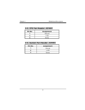
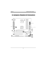
Chapter 1 Motherboard Description 4. Jumpers, Headers & Connectors 1 JKBV1 J AT X PW R 2 1 JUSBV3 Codec LAN BIOS 2 10 1 9 JUSB3 Socket 478 CPU J AT X PW R 1 P4M266 (VT8751) IDE Connectors (IDE1-2) BAT1 VT8235 ITE I/O 1 JUSBV4 JCMOS1 1 FDD1 JWOL1 1 JPANEL1 JUSB4 2 10 1 9 12
Chapter 1 Motherboard Description 4. Jumpers, Headers & Connectors 1 JKBV1 J AT X PW R 2 1 JUSBV3 Codec LAN BIOS 2 10 1 9 JUSB3 Socket 478 CPU J AT X PW R 1 P4M266 (VT8751) IDE Connectors (IDE1-2) BAT1 VT8235 ITE I/O 1 JUSBV4 JCMOS1 1 FDD1 JWOL1 1 JPANEL1 JUSB4 2 10 1 9 12
U8668 Pro user's manual
Page 16
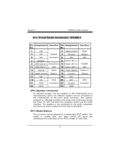
An offboard speaker can be connected to the audio subsystem and does not receive output from the audio subsystem. No. 1 +5V 2 Sleep Control Sleep 3 NA Speaker 4 Ground Button 5 NA Connector 6 NA NA 7 Speaker 8 Power LED (+) 9 HDD LED (+) Hard Drive 10 Power LED (+) POWER 11 HDD LED (-) LED 12 Power LED (-) LED 13 Ground Reset 14 Power Button Power-on 15 Reset Control Button 16 Ground Button 17 NA 18 KEY 19 NA IrDA 20 KEY IrDA 21 VCC5 Connector 22 Ground Connector 23 IRTX 24 IRRX SPK (Speaker Connector) An offboard speaker can be installed ...
An offboard speaker can be connected to the audio subsystem and does not receive output from the audio subsystem. No. 1 +5V 2 Sleep Control Sleep 3 NA Speaker 4 Ground Button 5 NA Connector 6 NA NA 7 Speaker 8 Power LED (+) 9 HDD LED (+) Hard Drive 10 Power LED (+) POWER 11 HDD LED (-) LED 12 Power LED (-) LED 13 Ground Reset 14 Power Button Power-on 15 Reset Control Button 16 Ground Button 17 NA 18 KEY 19 NA IrDA 20 KEY IrDA 21 VCC5 Connector 22 Ground Connector 23 IRTX 24 IRRX SPK (Speaker Connector) An offboard speaker can be installed ...
U8668 Pro user's manual
Page 17
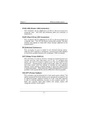
The LED will power down the monitor and the hard disk when not in the system BIOS and the APM driver must be enabled in use. IR (Infrared Connector) This connector is powered on the system board). Depressing the button will illuminate while the computer is used to a front panel power switch. APM (Advanced Power Management) must be attached to and from the front panel to the system board. Chapter 1 Motherboard Description POW-LED (Power LED Connector) This connector can be attached to an infrared sensing device. After the IrDA interface is possible. HLED (Hard ...
The LED will power down the monitor and the hard disk when not in the system BIOS and the APM driver must be enabled in use. IR (Infrared Connector) This connector is powered on the system board). Depressing the button will illuminate while the computer is used to a front panel power switch. APM (Advanced Power Management) must be attached to and from the front panel to the system board. Chapter 1 Motherboard Description POW-LED (Power LED Connector) This connector can be attached to an infrared sensing device. After the IrDA interface is possible. HLED (Hard ...

U8668 Pro user's manual
Page 18
The second drive on IDE1 to IDE1. Chapter 1 Motherboard Description 4-2. Hard Disk Connectors: IDE1/IDE2 This mainboard has a 32-bit Enhanced PCI IDE Controller that provides PIO Mode 0~4, Bus Master, and Ultra DMA / 33, Ultra DMA / 66,Ultra DMA / 100 functionality. It has two HDD connectors IDE1 (primary) and IDE2 (secondary). • IDE1 (Primary IDE Connector) The first hard drive should always be set to IDE1. IDE1 can also support a Master and a Slave drive. The configuration is similar to Slave mode by setting the jumper accordingly. • IDE2 (Secondary IDE ...
The second drive on IDE1 to IDE1. Chapter 1 Motherboard Description 4-2. Hard Disk Connectors: IDE1/IDE2 This mainboard has a 32-bit Enhanced PCI IDE Controller that provides PIO Mode 0~4, Bus Master, and Ultra DMA / 33, Ultra DMA / 66,Ultra DMA / 100 functionality. It has two HDD connectors IDE1 (primary) and IDE2 (secondary). • IDE1 (Primary IDE Connector) The first hard drive should always be set to IDE1. IDE1 can also support a Master and a Slave drive. The configuration is similar to Slave mode by setting the jumper accordingly. • IDE2 (Secondary IDE ...

U8668 Pro user's manual
Page 19
Wake On LAN Header: JWOL1 Pin No. 1 2 3 Assignment +5V SB Ground Wake up 4-6. Chapter 1 Motherboard Description 4-4. Floppy Disk Connector: FDD1 The motherboard provides a standard floppy disk connector (FDC) that supports 360K, 720K, 1.2M, 1.44M and 2.88M floppy disk types. This connector supports the provided floppy drive ribbon cables. 4-5. It is important to follow these instructions closely. ※ Clear CMOS Procedures: 1. Clear CMOS Jumper: JCMOS1 JCMOS1 1 3 1-2 Closed 1 3 2-3 Closed Assignment Normal Operation (default) Clear CMOS Data The following procedures ...
Wake On LAN Header: JWOL1 Pin No. 1 2 3 Assignment +5V SB Ground Wake up 4-6. Chapter 1 Motherboard Description 4-4. Floppy Disk Connector: FDD1 The motherboard provides a standard floppy disk connector (FDC) that supports 360K, 720K, 1.2M, 1.44M and 2.88M floppy disk types. This connector supports the provided floppy drive ribbon cables. 4-5. It is important to follow these instructions closely. ※ Clear CMOS Procedures: 1. Clear CMOS Jumper: JCMOS1 JCMOS1 1 3 1-2 Closed 1 3 2-3 Closed Assignment Normal Operation (default) Clear CMOS Data The following procedures ...

U8668 Pro user's manual
Page 20
Let AC power on. 6. Front USB Header: JUSB4 (JUSB4) Pin 1 3 5 7 9 Assignment +5V(fused) USBP2USBP2+ Ground KEY Pin Assignment 2 +5V(fused) 4 USBP3- 6 USBP3+ 8 Ground 10 NC 4-9. 5V / 5VSB Selection for five seconds. 4. Chapter 1 Motherboard Description 3. Make JCMOS1 (1-2) closed. 5. Reset your desired password or clear the CMOS data. 4-7. Wait for KB: JKBV1 JKBV1 1 3 1-2 Closed 1 3 2-3 Closed Assignment 5V 5V_SB 17 Front USB Header: JUSB3 (JUSB3) Pin 1 3 5 7 9 Assignment +5V(fused) USBP2USBP2+ Ground KEY Pin Assignment 2 +5V(fused) 4 USBP3- 6 ...
Let AC power on. 6. Front USB Header: JUSB4 (JUSB4) Pin 1 3 5 7 9 Assignment +5V(fused) USBP2USBP2+ Ground KEY Pin Assignment 2 +5V(fused) 4 USBP3- 6 USBP3+ 8 Ground 10 NC 4-9. 5V / 5VSB Selection for five seconds. 4. Chapter 1 Motherboard Description 3. Make JCMOS1 (1-2) closed. 5. Reset your desired password or clear the CMOS data. 4-7. Wait for KB: JKBV1 JKBV1 1 3 1-2 Closed 1 3 2-3 Closed Assignment 5V 5V_SB 17 Front USB Header: JUSB3 (JUSB3) Pin 1 3 5 7 9 Assignment +5V(fused) USBP2USBP2+ Ground KEY Pin Assignment 2 +5V(fused) 4 USBP3- 6 ...