

U8668 Pro user's manual
Page 2
...: IDE1/IDE2 15 4-4. Wake On LAN Header: JWOL1 16 4-6. CPU Fan Header: JCFAN1 11 3-3. Mainboard Configuration 7 2-1. CPU Configuration 9 3-1. Jumpers, Headers & Connectors 12 4-1. ATX 20-pin Power Connector: JATXPWR1 15 4-3. Table of U8668 Pro 7 2-2. Features Introduction 2 1-1. Layout of Contents Notice 1 Mainboard Features 2 1. CPU Socket 478 Configuration Steps 9 3-2. Front Panel Connector: JPANEL1 13 4-2. Floppy Disk Connector...
...: IDE1/IDE2 15 4-4. Wake On LAN Header: JWOL1 16 4-6. CPU Fan Header: JCFAN1 11 3-3. Mainboard Configuration 7 2-1. CPU Configuration 9 3-1. Jumpers, Headers & Connectors 12 4-1. ATX 20-pin Power Connector: JATXPWR1 15 4-3. Table of U8668 Pro 7 2-2. Features Introduction 2 1-1. Layout of Contents Notice 1 Mainboard Features 2 1. CPU Socket 478 Configuration Steps 9 3-2. Front Panel Connector: JPANEL1 13 4-2. Floppy Disk Connector...
U8668 Pro user's manual
Page 4
...devices such as Windows NT, Windows 2000, Windows ME, Windows XP, Novell, LINUX and SCO UNIX. 1 Complies with industry software and hardware standards. U8668 Pro Features: 1.Contains on board I/O facilities that include a serial port, a VGA port, a parallel port, a PS/2 mouse port, a PS/2 keyboard...Intel Pentium ® 4 processor, a leading edge processor. Chapter 1 Motherboard Description Notice Introduction of system This mainboard is designed to take advantage of its predecessors, this mainboard continues a commitment to provide you with the ultimate solution in data processing.
...devices such as Windows NT, Windows 2000, Windows ME, Windows XP, Novell, LINUX and SCO UNIX. 1 Complies with industry software and hardware standards. U8668 Pro Features: 1.Contains on board I/O facilities that include a serial port, a VGA port, a parallel port, a PS/2 mouse port, a PS/2 keyboard...Intel Pentium ® 4 processor, a leading edge processor. Chapter 1 Motherboard Description Notice Introduction of system This mainboard is designed to take advantage of its predecessors, this mainboard continues a commitment to provide you with the ultimate solution in data processing.
U8668 Pro user's manual
Page 5
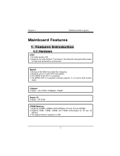
... speeds. 3.The 33MHz 32 bit PCI 2.2 compliant. 4.The 66MHz AGP 2.0 compliant interface supports 1x, 2x and 4x data transfer mode. Chipset: Chipset - Chapter 1 Motherboard Description Mainboard Features 1. VIA VT8751 (P4M266)/ VT8235. ITE 8705 DRAM Memory: 1.Supports 200MHz, 266MHz DDR SDRAM or PC100, PC133 SDRAM. 2.Supports 64Mb, 128Mb, 256Mb and 512Mb technologies...
... speeds. 3.The 33MHz 32 bit PCI 2.2 compliant. 4.The 66MHz AGP 2.0 compliant interface supports 1x, 2x and 4x data transfer mode. Chipset: Chipset - Chapter 1 Motherboard Description Mainboard Features 1. VIA VT8751 (P4M266)/ VT8235. ITE 8705 DRAM Memory: 1.Supports 200MHz, 266MHz DDR SDRAM or PC100, PC133 SDRAM. 2.Supports 64Mb, 128Mb, 256Mb and 512Mb technologies...
U8668 Pro user's manual
Page 10
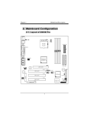
LAN AGP SLOT IDE1 IDE2 PCI SLOT PCI SLOT PCI1 PCI2 JUSBV3 1 1 JUSBV4 2 10 2 10 1 91 9 JUSB3 JUSB4 B AT 1 VT8235 1 JCMOS1 FDD1 PCI3 PCI SLOT CNR1 CNR SLOT JWOL1 1 ITE I/O JPANEL1 2 24 1 23 7 Game Port In Out MIC Line Speaker JVGA1 JATXPWR2 P4M266 (VT8751) In Codec 1 JCDIN1 BIOS FLOPPY DISK CONN. SECONDARY IDE CONN. Mainboard Configuration 2-1. Layout of U8668 Pro JKBMS1 K/B & Mouse JUSBLAN USB & LAN JCOM1 JPRNT1 CPU1 Socket 478 CPU JATXPWR1 COM1 Parallel Port VGA1 PRIMARY IDE CONN. Chapter 1 Motherboard Description 2.
LAN AGP SLOT IDE1 IDE2 PCI SLOT PCI SLOT PCI1 PCI2 JUSBV3 1 1 JUSBV4 2 10 2 10 1 91 9 JUSB3 JUSB4 B AT 1 VT8235 1 JCMOS1 FDD1 PCI3 PCI SLOT CNR1 CNR SLOT JWOL1 1 ITE I/O JPANEL1 2 24 1 23 7 Game Port In Out MIC Line Speaker JVGA1 JATXPWR2 P4M266 (VT8751) In Codec 1 JCDIN1 BIOS FLOPPY DISK CONN. SECONDARY IDE CONN. Mainboard Configuration 2-1. Layout of U8668 Pro JKBMS1 K/B & Mouse JUSBLAN USB & LAN JCOM1 JPRNT1 CPU1 Socket 478 CPU JATXPWR1 COM1 Parallel Port VGA1 PRIMARY IDE CONN. Chapter 1 Motherboard Description 2.

U8668 Pro user's manual
Page 18
Hard Disk Connectors: IDE1/IDE2 This mainboard has a 32-bit Enhanced PCI IDE Controller that provides PIO Mode 0~4, Bus Master, and Ultra DMA / 33, Ultra DMA / 66,Ultra DMA / 100 functionality. ATX ...
Hard Disk Connectors: IDE1/IDE2 This mainboard has a 32-bit Enhanced PCI IDE Controller that provides PIO Mode 0~4, Bus Master, and Ultra DMA / 33, Ultra DMA / 66,Ultra DMA / 100 functionality. ATX ...
U8668 Pro user's manual
Page 24
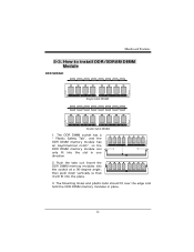
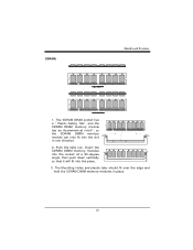
Mainboard Features 5-3. How to install DDR/SDRAM DIMM Module DDR SDRAM: Single Sided DIMM Double Sided DIMM 1. The DDR DIMM socket has a " Plastic Safety Tab", and the DDR DIMM memory module has an Asymmetrical notch", so the DDR DIMM memory module can only fit into the place. 3. Insert the DDR DIMM memory modules into the socket at a 90-degree angle, then push down vertically so that it will fit into the slot in place. 21 Push the tabs out. The Mounting Holes and plastic tabs should fit over the edge and hold the DDR DIMM memory modules in one direction. 2.
Mainboard Features 5-3. How to install DDR/SDRAM DIMM Module DDR SDRAM: Single Sided DIMM Double Sided DIMM 1. The DDR DIMM socket has a " Plastic Safety Tab", and the DDR DIMM memory module has an Asymmetrical notch", so the DDR DIMM memory module can only fit into the place. 3. Insert the DDR DIMM memory modules into the socket at a 90-degree angle, then push down vertically so that it will fit into the slot in place. 21 Push the tabs out. The Mounting Holes and plastic tabs should fit over the edge and hold the DDR DIMM memory modules in one direction. 2.
U8668 Pro user's manual
Page 25
Push the tabs out. The Mounting Holes and plastic tabs should fit over the edge and hold the SDRAM DIMM memory modules in one direction. 2. SDRAM: Mainboard Features 1. Insert the SDRAM DIMM memory modules into the socket at a 90-degree angle, then push down vertically so that it will fit into the slot in place. 22 The SDRAM DIMM socket has a " Plastic Safety Tab", and the SDRAM DIMM memory module has an Asymmetrical notch", so the SDRAM DIMM memory module can only fit into the place. 3.
Push the tabs out. The Mounting Holes and plastic tabs should fit over the edge and hold the SDRAM DIMM memory modules in one direction. 2. SDRAM: Mainboard Features 1. Insert the SDRAM DIMM memory modules into the socket at a 90-degree angle, then push down vertically so that it will fit into the slot in place. 22 The SDRAM DIMM socket has a " Plastic Safety Tab", and the SDRAM DIMM memory module has an Asymmetrical notch", so the SDRAM DIMM memory module can only fit into the place. 3.
U8668 Pro user's manual
Page 26
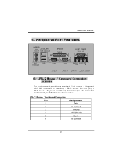
.../2 mouse. The connector location and pin definition are shown below: PS/2 Mouse / Keyboard Connectors Pin 1 2 3 4 5 6 Assignment Data No connect Ground +5 V (fused) Clock No connect 23 Mainboard Features 6. You can plug a PS/2 mouse / Keyboard directly into this connector. Peripheral Port Features JKBMS1 PS/2 JUSBLAN1 Mouse LAN (Optional) JPRNT1 Parallel JAUD_GAME Game Port...
.../2 mouse. The connector location and pin definition are shown below: PS/2 Mouse / Keyboard Connectors Pin 1 2 3 4 5 6 Assignment Data No connect Ground +5 V (fused) Clock No connect 23 Mainboard Features 6. You can plug a PS/2 mouse / Keyboard directly into this connector. Peripheral Port Features JKBMS1 PS/2 JUSBLAN1 Mouse LAN (Optional) JPRNT1 Parallel JAUD_GAME Game Port...
U8668 Pro user's manual
Page 27
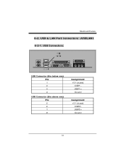
USB Connectors: USB Connector (the below one) Pin 1 2 3 4 USB Connector (the above one) Pin 5 6 7 8 Assignment +5 V (fused) USBP1USBP1+ Ground Assignment +5 V (fused) USBP2USBP2+ Ground 24 Mainboard Features 6-2. USB & LAN Port Connectors: JUSBLAN1 6-2-1.
USB Connectors: USB Connector (the below one) Pin 1 2 3 4 USB Connector (the above one) Pin 5 6 7 8 Assignment +5 V (fused) USBP1USBP1+ Ground Assignment +5 V (fused) USBP2USBP2+ Ground 24 Mainboard Features 6-2. USB & LAN Port Connectors: JUSBLAN1 6-2-1.
U8668 Pro user's manual
Page 28
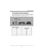
You can set up the connection by entering account information provided by your ISP. LAN Port Connector (Optional) This connector allows you to connect to the Internet through a Local Area Network (LAN). LAN Port Connector Pin 9 10 11 12 13 14 Assignment VCC3 TD+ TDRD+ RDNC 25 Mainboard Features 6-2-2.
You can set up the connection by entering account information provided by your ISP. LAN Port Connector (Optional) This connector allows you to connect to the Internet through a Local Area Network (LAN). LAN Port Connector Pin 9 10 11 12 13 14 Assignment VCC3 TD+ TDRD+ RDNC 25 Mainboard Features 6-2-2.
U8668 Pro user's manual
Page 29
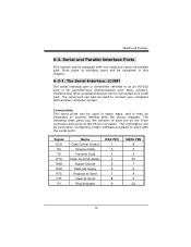
... pin on the 9-pin connector and some of interface ports will be connected to connect your computer with one serial port and one parallel port. Mainboard Features 6-3. The serial port can be explained in many ways, and it may be used to a serial port.
... pin on the 9-pin connector and some of interface ports will be connected to connect your computer with one serial port and one parallel port. Mainboard Features 6-3. The serial port can be explained in many ways, and it may be used to a serial port.
U8668 Pro user's manual
Page 30
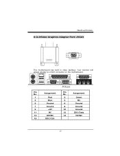
Assignment 1 Red 2 Green 3 Blue 4 NC 5 Ground 6 Ground 7 Ground 8 Ground 9 +5V 10 Ground 11 NC 12 DDC/Data 13 HSYNC 14 VSYNC 15 DDC/CLK 27 Mainboard Features 6-3-2Video Graphics Adapter Port: JVGA1 This motherboard has built in video facilities. Assignment Pin No. Your monitor will attach directly to JVGA1 connector on the motherboard. 5 1 15 11 JVGA1 Pin No.
Assignment 1 Red 2 Green 3 Blue 4 NC 5 Ground 6 Ground 7 Ground 8 Ground 9 +5V 10 Ground 11 NC 12 DDC/Data 13 HSYNC 14 VSYNC 15 DDC/CLK 27 Mainboard Features 6-3-2Video Graphics Adapter Port: JVGA1 This motherboard has built in video facilities. Assignment Pin No. Your monitor will attach directly to JVGA1 connector on the motherboard. 5 1 15 11 JVGA1 Pin No.
U8668 Pro user's manual
Page 31
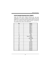
The pinout for the parallel port are shown in the table below. Mainboard Features 6-3-3. Parallel Interface Port: JPRNT1 Unlike the serial ports, parallel interface port has been standardized and should not present any difficulty interfacing peripherals to your ...
The pinout for the parallel port are shown in the table below. Mainboard Features 6-3-3. Parallel Interface Port: JPRNT1 Unlike the serial ports, parallel interface port has been standardized and should not present any difficulty interfacing peripherals to your ...
U8668 Pro user's manual
Page 32
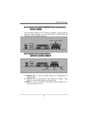
... or edit professional music by connecting MIDI devices. Game/Joystick/MIDI 6-5. Line In can be connected to connect a joystick or game pad for audio output. 2. Mainboard Features 6-4. Also, you to the external CD player, Tape player or other audio devices for audio input. 3.
... or edit professional music by connecting MIDI devices. Game/Joystick/MIDI 6-5. Line In can be connected to connect a joystick or game pad for audio output. 2. Mainboard Features 6-4. Also, you to the external CD player, Tape player or other audio devices for audio input. 3.