

Setup Manual
Page 2
Table of Contents Chapter 1: Introduction 1 1.1 Before You Start 1 1.2 Package Checklist 1 1.3 Motherboard Features 2 1.4 Rear Panel Connectors 3 1.5 Motherboard Layout 4 Chapter 2: Hardware Installation 5 2.1 Installing Central Processing Unit (CPU 5 2.2 FAN Headers 7 2.3 Installing System Memory 8 2.4 Connectors and Slots 10 Chapter 3: Headers & Jumpers Setup 12 3.1 How to ...
Table of Contents Chapter 1: Introduction 1 1.1 Before You Start 1 1.2 Package Checklist 1 1.3 Motherboard Features 2 1.4 Rear Panel Connectors 3 1.5 Motherboard Layout 4 Chapter 2: Hardware Installation 5 2.1 Installing Central Processing Unit (CPU 5 2.2 FAN Headers 7 2.3 Installing System Memory 8 2.4 Connectors and Slots 10 Chapter 3: Headers & Jumpers Setup 12 3.1 How to ...

Setup Manual
Page 3
... may damage the equipment. „ Keep the computer from anti-static bag, ground yourself properly by area or your motherboard version. 1 CHAPTER 1: INTRODUCTION MCP6PB M2+/N68S 1.1 BEFORE YOU START Thank you take the motherboard out from dangerous area, such as heat source, humid air and water. 1.2 PACKAGE CHECKLIST IDE Cable X 1 (optional) Serial ATA...
... may damage the equipment. „ Keep the computer from anti-static bag, ground yourself properly by area or your motherboard version. 1 CHAPTER 1: INTRODUCTION MCP6PB M2+/N68S 1.1 BEFORE YOU START Thank you take the motherboard out from dangerous area, such as heat source, humid air and water. 1.2 PACKAGE CHECKLIST IDE Cable X 1 (optional) Serial ATA...

Setup Manual
Page 4
Motherboard Manual 1.3 MOTHERBOARD FEATURES SPEC Socket AM2+ AMD 64 Architecture enables 32 and 64 bit AMD...Ghz FSB Supports up to 2 GT/s Bandwidth Chipset GeForce 6150 SE/nForce 430 (MCP6P M2+) GeForce 7025/nForce 630a (N68S) ITE 8718F Super I/O Provides the most commonly used legacy Super I/O functionality Low Pin Count Interface Environment Control initiatives H/W Monitor...DIMM and ECC DIMM is not supported Graphics GeForce 6150 SE/nForce 430 (MCP6P M2+) GeForce 7025/nForce 630a (N68S) Max Shared Video Memory is 256MB IDE Integrated IDE Controller Ultra DMA 33 / 66 / 100 / 133 ...
Motherboard Manual 1.3 MOTHERBOARD FEATURES SPEC Socket AM2+ AMD 64 Architecture enables 32 and 64 bit AMD...Ghz FSB Supports up to 2 GT/s Bandwidth Chipset GeForce 6150 SE/nForce 430 (MCP6P M2+) GeForce 7025/nForce 630a (N68S) ITE 8718F Super I/O Provides the most commonly used legacy Super I/O functionality Low Pin Count Interface Environment Control initiatives H/W Monitor...DIMM and ECC DIMM is not supported Graphics GeForce 6150 SE/nForce 430 (MCP6P M2+) GeForce 7025/nForce 630a (N68S) Max Shared Video Memory is 256MB IDE Integrated IDE Controller Ultra DMA 33 / 66 / 100 / 133 ...

Setup Manual
Page 8
... the CPU FAN power cable to the latest version while using new AM2+ CPUs. Step 5: Put the CPU Fan on the CPU and buckle it. Motherboard Manual Step 4: Hold the CPU down firmly, and then close the lever toward direct B to complete the installation.
... the CPU FAN power cable to the latest version while using new AM2+ CPUs. Step 5: Put the CPU Fan on the CPU and buckle it. Motherboard Manual Step 4: Hold the CPU down firmly, and then close the lever toward direct B to complete the installation.
Setup Manual
Page 10
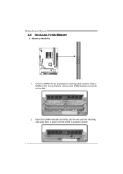
Align a DIMM on the slot so that the notch on the DIMM matches the break on the Slot. 2. Memory Modules 1. Unlock a DIMM slot by pressing the retaining clips outward. DIM MA1 DIM MB1 Motherboard Manual 2.3 INSTALLING SYSTEM MEMORY A. Insert the DIMM vertically and firmly into the slot until the retaining chip snap back in place and the DIMM is properly seated. 8
Align a DIMM on the slot so that the notch on the DIMM matches the break on the Slot. 2. Memory Modules 1. Unlock a DIMM slot by pressing the retaining clips outward. DIM MA1 DIM MB1 Motherboard Manual 2.3 INSTALLING SYSTEM MEMORY A. Insert the DIMM vertically and firmly into the slot until the retaining chip snap back in place and the DIMM is properly seated. 8
Setup Manual
Page 11
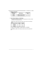
... O O (O means memory installed, X means memory not installed.) The DRAM bus width of the memory module must meet the following requirements: Install memory module of the motherboard, the memory module must be the same (x8 or x16) 9 B. Memory Capacity DIMM Socket Location DDR2 Module DIMMA1 256MB/512MB/1GB/2GB DIMMB1 256MB/512MB...
... O O (O means memory installed, X means memory not installed.) The DRAM bus width of the memory module must meet the following requirements: Install memory module of the motherboard, the memory module must be the same (x8 or x16) 9 B. Memory Capacity DIMM Socket Location DDR2 Module DIMMA1 256MB/512MB/1GB/2GB DIMMB1 256MB/512MB...
Setup Manual
Page 12
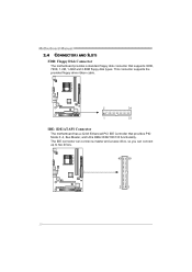
The IDE connector can connect a master and a slave drive, so you can connect up to two drives. 40 39 21 10 This connector supports the provided floppy drive ribbon cable. 2 34 1 33 IDE: IDE/ATAPI Connector The motherboard has a 32-bit Enhanced PCI IDE Controller that supports 360K, 720K, 1.2M, 1.44M and 2.88M floppy disk types. Motherboard Manual 2.4 CONNECTORS AND SLOTS FDD: Floppy Disk Connector The motherboard provides a standard floppy disk connector that provides PIO Mode 0~4, Bus Master, and Ultra DMA 33/66/100/133 functionality.
The IDE connector can connect a master and a slave drive, so you can connect up to two drives. 40 39 21 10 This connector supports the provided floppy drive ribbon cable. 2 34 1 33 IDE: IDE/ATAPI Connector The motherboard has a 32-bit Enhanced PCI IDE Controller that supports 360K, 720K, 1.2M, 1.44M and 2.88M floppy disk types. Motherboard Manual 2.4 CONNECTORS AND SLOTS FDD: Floppy Disk Connector The motherboard provides a standard floppy disk connector that provides PIO Mode 0~4, Bus Master, and Ultra DMA 33/66/100/133 functionality.
Setup Manual
Page 13
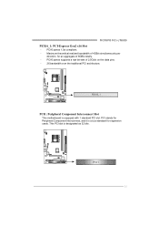
Maximum theoretical realized bandwidth of 4GB/s simultaneously per direction, for expansion cards. PCI-Express supports a raw bit-rate of 8GB/s totally. - PEX16_1 PCI1: Peripheral Component Interconnect Slot This motherboard is designated as 32 bits. PCI stands for Peripheral Component Interconnect, and it is a bus standard for an aggregate of 2.5Gb/s on the data pins. - 2X bandwidth over the traditional PCI architecture. PCI1 11 PCI-Express 1.0a compliant. - This PCI slot is equipped with 1 standard PCI slot. MCP6PB M2+/N68S PEX16_1: PCI-Express Gen2 x16 Slot -
Maximum theoretical realized bandwidth of 4GB/s simultaneously per direction, for expansion cards. PCI-Express supports a raw bit-rate of 8GB/s totally. - PEX16_1 PCI1: Peripheral Component Interconnect Slot This motherboard is designated as 32 bits. PCI stands for Peripheral Component Interconnect, and it is a bus standard for an aggregate of 2.5Gb/s on the data pins. - 2X bandwidth over the traditional PCI architecture. PCI1 11 PCI-Express 1.0a compliant. - This PCI slot is equipped with 1 standard PCI slot. MCP6PB M2+/N68S PEX16_1: PCI-Express Gen2 x16 Slot -

Setup Manual
Page 14
... closed Pin1-2 closed 3.2 DETAIL SETTINGS JPANEL1: Front Panel Header This 16-pin connector includes Power-on, Reset, HDD LED, Power LED, Sleep, and speaker connection. Motherboard Manual CHAPTER 3: HEADERS & JUMPERS SETUP 3.1 HOW TO SETUP JUMPERS The illustration shows how to connect the PC case's front panel switch functions.
... closed Pin1-2 closed 3.2 DETAIL SETTINGS JPANEL1: Front Panel Header This 16-pin connector includes Power-on, Reset, HDD LED, Power LED, Sleep, and speaker connection. Motherboard Manual CHAPTER 3: HEADERS & JUMPERS SETUP 3.1 HOW TO SETUP JUMPERS The illustration shows how to connect the PC case's front panel switch functions.

Setup Manual
Page 16
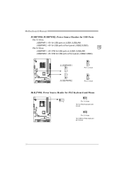
...21 Pin Assignment 1 +5V (fused) 2 +5V (fused) 3 USB4 USB5 USB+ 6 USB+ 7 Ground 8 Ground 9 NC 10 Key SATA1/SATA2: Serial ATA Connectors The motherboard has a PCI to connect additional USB cable on the PC front panel, and also can be connected with transfer rate of 3.0Gb/s. SATA2 SATA1 14... 7 Pin Assignment 1 Ground 2 TX+ 3 TX4 Ground 5 RX6 RX+ 7 Ground 14 Motherboard Manual JUSB2/JUSB3: Headers for USB 2.0 Ports at Front Panel These headers allow user to SATA Controller with 2 channels SATA interface, it satisfies the SATA...
...21 Pin Assignment 1 +5V (fused) 2 +5V (fused) 3 USB4 USB5 USB+ 6 USB+ 7 Ground 8 Ground 9 NC 10 Key SATA1/SATA2: Serial ATA Connectors The motherboard has a PCI to connect additional USB cable on the PC front panel, and also can be connected with transfer rate of 3.0Gb/s. SATA2 SATA1 14... 7 Pin Assignment 1 Ground 2 TX+ 3 TX4 Ground 5 RX6 RX+ 7 Ground 14 Motherboard Manual JUSB2/JUSB3: Headers for USB 2.0 Ports at Front Panel These headers allow user to SATA Controller with 2 channels SATA interface, it satisfies the SATA...

Setup Manual
Page 17
...2 Ground 3 Mic Right in 4 GPIO 5 Right line in 6 Jack Sense 7 Front Sense 8 Key 9 Left line in 10 Jack Sense 1 9 JCOM: Serial port Connector The motherboard has a Serial Port Connector for connecting RS-232 Port. 2 10 1 9 Pin Assignment 1 Carrier detect 2 Received data 3 Transmitted data 4 Data terminal ready 5 Signal ground 6 Data...Clear to connect the front audio output cable with the PC front panel. This header allows only HD audio front panel connector; MCP6PB M2+/N68S JAUDIOF: Front Panel Audio Header This header allows user to send 9 Ring indicator 10 NC 15
...2 Ground 3 Mic Right in 4 GPIO 5 Right line in 6 Jack Sense 7 Front Sense 8 Key 9 Left line in 10 Jack Sense 1 9 JCOM: Serial port Connector The motherboard has a Serial Port Connector for connecting RS-232 Port. 2 10 1 9 Pin Assignment 1 Carrier detect 2 Received data 3 Transmitted data 4 Data terminal ready 5 Signal ground 6 Data...Clear to connect the front audio output cable with the PC front panel. This header allows only HD audio front panel connector; MCP6PB M2+/N68S JAUDIOF: Front Panel Audio Header This header allows user to send 9 Ring indicator 10 NC 15

Setup Manual
Page 18
Power on pin2-3, it allows user to restore the BIOS safe setting and the CMOS data, please carefully follow the procedures to avoid damaging the motherboard. 31 Pin 1-2 Close: Normal Operation (default). 31 31 Pin 2-3 Close: Clear CMOS data. ※ Clear CMOS Procedures: 1. Reset your desired password or clear the CMOS data. 16 Set the jumper to "Pin 2-3 close ". 5. Set the jumper to "Pin 1-2 close ". 3. Wait for five seconds. 4. Remove AC power line. 2. Motherboard Manual JCMOS1: Clear CMOS Header By placing the jumper on the AC. 6.
Power on pin2-3, it allows user to restore the BIOS safe setting and the CMOS data, please carefully follow the procedures to avoid damaging the motherboard. 31 Pin 1-2 Close: Normal Operation (default). 31 31 Pin 2-3 Close: Clear CMOS data. ※ Clear CMOS Procedures: 1. Reset your desired password or clear the CMOS data. 16 Set the jumper to "Pin 2-3 close ". 5. Set the jumper to "Pin 1-2 close ". 3. Wait for five seconds. 4. Remove AC power line. 2. Motherboard Manual JCMOS1: Clear CMOS Header By placing the jumper on the AC. 6.
Setup Manual
Page 20
JUSBPWR2: +5V for PS/2 keyboard and mouse. 18 JUSBPWR1 1 3 3 1 JUSBPWR2 1 3 Pin 1-2 close 1 3 Pin 2-3 close JKB_PWR: Power Source Header for PS/2 Keyboard and Mouse 1 3 1 3 Pin 1-2 close +5V for PS/2 keyboard and mouse. 1 3 Pin 2-3 close +5V STB for USB ports at JUSB1/JUSBLAN1. JUSBPWR2: +5V STB for USB ports at front panel (JUSB2/JUSB3). Pin 2-3 Close: JUSBPWR1: +5V STB for USB ports at JUSB1/JUSBLAN1. Motherboard Manual JUSBPWR1/JUSBPWR2: Power Source Headers for USB Ports Pin 1-2 Close: JUSBPWR1: +5V for USB ports at front panel (JUSB2/JUSB3).
JUSBPWR2: +5V for PS/2 keyboard and mouse. 18 JUSBPWR1 1 3 3 1 JUSBPWR2 1 3 Pin 1-2 close 1 3 Pin 2-3 close JKB_PWR: Power Source Header for PS/2 Keyboard and Mouse 1 3 1 3 Pin 1-2 close +5V for PS/2 keyboard and mouse. 1 3 Pin 2-3 close +5V STB for USB ports at JUSB1/JUSBLAN1. JUSBPWR2: +5V STB for USB ports at front panel (JUSB2/JUSB3). Pin 2-3 Close: JUSBPWR1: +5V STB for USB ports at JUSB1/JUSBLAN1. Motherboard Manual JUSBPWR1/JUSBPWR2: Power Source Headers for USB Ports Pin 1-2 Close: JUSBPWR1: +5V for USB ports at front panel (JUSB2/JUSB3).
Setup Manual
Page 22
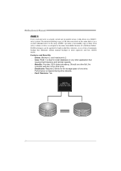
... backup that requires fault tolerance and minimal capacity. Benefits: Provides 100% data redundancy. RAID 1 provides a hot-standby copy of a hardware failure. Should one drive. Motherboard Manual RAID 1: Every read and write is actually carried out in parallel across 2 disk drives in the array. Performance is corrupted or becomes unavailable because...
... backup that requires fault tolerance and minimal capacity. Benefits: Provides 100% data redundancy. RAID 1 provides a hot-standby copy of a hardware failure. Should one drive. Motherboard Manual RAID 1: Every read and write is actually carried out in parallel across 2 disk drives in the array. Performance is corrupted or becomes unavailable because...
Setup Manual
Page 23
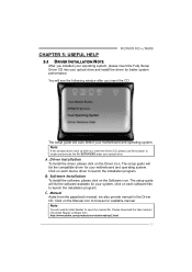
... available for your system, click on each device driver to launch the installation program. A. The setup guide will auto detect your motherboard and operating system. Please download the latest version of Acrobat Reader software from the paperback manual, we also provide manual in the Driver...guide will need Acrobat Reader to locate and execute the file SETUP.EXE under your optical drive. CHAPTER 5: USEFUL HELP MCP6PB M2+/N68S 5.1 DRIVER INSTALLATION NOTE After you installed your operating system, please insert the Fully Setup Driver CD into your optical drive and install ...
... available for your system, click on each device driver to launch the installation program. A. The setup guide will auto detect your motherboard and operating system. Please download the latest version of Acrobat Reader software from the paperback manual, we also provide manual in the Driver...guide will need Acrobat Reader to locate and execute the file SETUP.EXE under your optical drive. CHAPTER 5: USEFUL HELP MCP6PB M2+/N68S 5.1 DRIVER INSTALLATION NOTE After you installed your operating system, please insert the Fully Setup Driver CD into your optical drive and install ...

Setup Manual
Page 24
..., and then click on -screen instructions to update boo logo: 1. You can choose JPG or BMP as your boot logo so as the boot logo. 2. Motherboard Manual 5.2 SOFTWARE Installing Software 1. Insert the Setup CD to complete the update. 22
..., and then click on -screen instructions to update boo logo: 1. You can choose JPG or BMP as your boot logo so as the boot logo. 2. Motherboard Manual 5.2 SOFTWARE Installing Software 1. Insert the Setup CD to complete the update. 22

Setup Manual
Page 25
...: 1. CPU fan speed is over heated, the motherboard will shut down automatically One Short beep when system boot-up the system. Wait for seconds. 3. Power on system for seconds. 2. CPU fan is placed evenly with the CPU speed. Or you can: 1. MCP6PB M2+/N68S 5.3 AWARD BIOS BEEP CODE Beep Sound Meaning One...
...: 1. CPU fan speed is over heated, the motherboard will shut down automatically One Short beep when system boot-up the system. Wait for seconds. 3. Power on system for seconds. 2. CPU fan is placed evenly with the CPU speed. Or you can: 1. MCP6PB M2+/N68S 5.3 AWARD BIOS BEEP CODE Beep Sound Meaning One...

Setup Manual
Page 26
... is no power in the standard CMOS setup. the securely plugged in ; Check cable running . Reformat the hard drive. fan of are securely plugged in . Motherboard Manual 5.5 TROUBLESHOOTING Probable Solution 1. System only boots from optical drive. 2. Re-install applications and data using backup disks.
... is no power in the standard CMOS setup. the securely plugged in ; Check cable running . Reformat the hard drive. fan of are securely plugged in . Motherboard Manual 5.5 TROUBLESHOOTING Probable Solution 1. System only boots from optical drive. 2. Re-install applications and data using backup disks.

