Setup Manual
Page 1
... a residential installation. D uplication of this publication and to make c hanges to the c ontents here without first obtaining the vendor's approval in a particular ins tallation. 945G-M7 / 945P-M7 FCC Information and Copyright This equipment has been tes ted and found in this user's manual is subject to the contents here and s pecially disclaims...
... a residential installation. D uplication of this publication and to make c hanges to the c ontents here without first obtaining the vendor's approval in a particular ins tallation. 945G-M7 / 945P-M7 FCC Information and Copyright This equipment has been tes ted and found in this user's manual is subject to the contents here and s pecially disclaims...
Setup Manual
Page 3
... Chip: ITE 8712F. WARNING! Environment Control initiatives, H/W Monitor Fan Speed Controller ITE's "Smart Guardian" function 1 945G-M7 / 945P-M7 CHAPTER 1: INTRODUCTION 1.1 MOTHERBOARD FEATURES C PU Supports LGA 775. Front Side Bus at the following frequency ranges: 533MHz (133MHz Core Clock...Technology. (HT) Supports Execute Disable Bit Technology (XD). Supports Intel Pentium D processor. Chi pset North Bridge: Intel 945G (945G-M7)/ Intel 945P (945P-M7). Supports Intel Pentium 4 processor up to pr otect the soc ket pin when s ending this mai nboard for ...
... Chip: ITE 8712F. WARNING! Environment Control initiatives, H/W Monitor Fan Speed Controller ITE's "Smart Guardian" function 1 945G-M7 / 945P-M7 CHAPTER 1: INTRODUCTION 1.1 MOTHERBOARD FEATURES C PU Supports LGA 775. Front Side Bus at the following frequency ranges: 533MHz (133MHz Core Clock...Technology. (HT) Supports Execute Disable Bit Technology (XD). Supports Intel Pentium D processor. Chi pset North Bridge: Intel 945G (945G-M7)/ Intel 945P (945P-M7). Supports Intel Pentium 4 processor up to pr otect the soc ket pin when s ending this mai nboard for ...
Setup Manual
Page 4
... to 4GB. Support 6 channels. Expansion Sl ots Two 32bit PCI bus master slots. One PCI-Express x1 slot. 10/100 LAN (optional) PHY: RTL8100C. 945G-M7 / 945P-M7 System Memory Supports Dual Channel DDR2. On Board IDE One on-board connector supports 2 devices. Compliant with AC'97 Version 2.3 specification. Supports 10 Mb/s and...
... to 4GB. Support 6 channels. Expansion Sl ots Two 32bit PCI bus master slots. One PCI-Express x1 slot. 10/100 LAN (optional) PHY: RTL8100C. 945G-M7 / 945P-M7 System Memory Supports Dual Channel DDR2. On Board IDE One on-board connector supports 2 devices. Compliant with AC'97 Version 2.3 specification. Supports 10 Mb/s and...

Setup Manual
Page 5
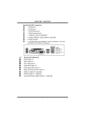
...-opened warning function. 1 Floppy port supports 2 FDD with 360K, 720K, 1.2M, 1.44M and 2.88Mbytes. 2 USB headers support 4 USB 2.0 ports. 4 Serial ATA connectors support 4 SATA devices. 3 945G-M7 / 945P-M7 Gigabit LAN (optional) Chip: RTL8110S. Supports ACPI power management. Half/Full duplex capability.
...-opened warning function. 1 Floppy port supports 2 FDD with 360K, 720K, 1.2M, 1.44M and 2.88Mbytes. 2 USB headers support 4 USB 2.0 ports. 4 Serial ATA connectors support 4 SATA devices. 3 945G-M7 / 945P-M7 Gigabit LAN (optional) Chip: RTL8110S. Supports ACPI power management. Half/Full duplex capability.
Setup Manual
Page 6
... CHECKLIST FDD Cable X 1 HDD Cable X 1 User's Manual X 1 Serial ATA Cable X 1 Fully Setup Driver CD X 1 Rear I n 1/ B as s/ Center 4 945G-M7 / 945P-M7 Back Panel I/O Conne ctors 1 Serial port. 1 Printer port. 1 PS/2 Mouse port. 1 PS/2 Keyboard port. 1 VGA port. (only for AT X Case X 1 USB...2.0 Cable X1 (optional) S/PDIF Cable X 1 (optional) Serial ATA Power Switch Cable X 1 (optional) Line In/ Surround Line Out Mi c I /O Panel for 945G-M7) 1 RJ-45 LAN jack / Giga LAN jack. (optional) 4 USB 2.0 ports. 1 vertical audio port including 1 line-in connector, 1 line-out connector, and 1 MIC...
... CHECKLIST FDD Cable X 1 HDD Cable X 1 User's Manual X 1 Serial ATA Cable X 1 Fully Setup Driver CD X 1 Rear I n 1/ B as s/ Center 4 945G-M7 / 945P-M7 Back Panel I/O Conne ctors 1 Serial port. 1 Printer port. 1 PS/2 Mouse port. 1 PS/2 Keyboard port. 1 VGA port. (only for AT X Case X 1 USB...2.0 Cable X1 (optional) S/PDIF Cable X 1 (optional) Serial ATA Power Switch Cable X 1 (optional) Line In/ Surround Line Out Mi c I /O Panel for 945G-M7) 1 RJ-45 LAN jack / Giga LAN jack. (optional) 4 USB 2.0 ports. 1 vertical audio port including 1 line-in connector, 1 line-out connector, and 1 MIC...

Setup Manual
Page 7
EX1_1 PC I1 PCI 2 JS PD IF_OU T1 J SP DIF_IN 1 (o p ti o n a l ) BI OS J DJ 1 (o p ti o n a l ) BAT1 J_C IR 1 (o p ti o n a )l Intel ICH7 SATA4 SATA2 SATA 3 S ATA1 JC I1 JC MOS 1 J SFAN 1 JPAN EL1 Note: ■ represents the 1st pin. 5 945G-M7 / 945P-M7 1.3 LAYOUT AND COMPONENTS JATXP WR2 JCFAN 1 JKB MS 1 LGA7 75 COMJC1OM1 CPU1 F DD1 JPR NT1 DDR2_A 1 DDR2_A2 DDR2_B 1 DDR2_B2 JV GA1 (only for 945G -M 7) IDE1 JRJ45USB 1 Su p er I /O JA UDIO1 J A UD IO2 JAT XPWR 1 PCI-E X 16 94 5G or 9 45P J C DIN 1 COD EC Giga LA N / L AN PCI-
EX1_1 PC I1 PCI 2 JS PD IF_OU T1 J SP DIF_IN 1 (o p ti o n a l ) BI OS J DJ 1 (o p ti o n a l ) BAT1 J_C IR 1 (o p ti o n a )l Intel ICH7 SATA4 SATA2 SATA 3 S ATA1 JC I1 JC MOS 1 J SFAN 1 JPAN EL1 Note: ■ represents the 1st pin. 5 945G-M7 / 945P-M7 1.3 LAYOUT AND COMPONENTS JATXP WR2 JCFAN 1 JKB MS 1 LGA7 75 COMJC1OM1 CPU1 F DD1 JPR NT1 DDR2_A 1 DDR2_A2 DDR2_B 1 DDR2_B2 JV GA1 (only for 945G -M 7) IDE1 JRJ45USB 1 Su p er I /O JA UDIO1 J A UD IO2 JAT XPWR 1 PCI-E X 16 94 5G or 9 45P J C DIN 1 COD EC Giga LA N / L AN PCI-

Setup Manual
Page 8
945G-M7 / 945P-M7 CHAPTER 2: HARDWARE INSTALLATION 2.1 INSTALLING CENTRAL PROCESSING UNIT (CPU) Special Notice: Remove Pin Cap before installation, and make good preservation for future use. Pin Cap Step 1: Pull the socket locking lever out from the socket and then raise the lever up to ensure pin legs won't be damaged. When the CPU is removed, cover the Pin Cap on the empty socket to a 90-degree angle. 6
945G-M7 / 945P-M7 CHAPTER 2: HARDWARE INSTALLATION 2.1 INSTALLING CENTRAL PROCESSING UNIT (CPU) Special Notice: Remove Pin Cap before installation, and make good preservation for future use. Pin Cap Step 1: Pull the socket locking lever out from the socket and then raise the lever up to ensure pin legs won't be damaged. When the CPU is removed, cover the Pin Cap on the empty socket to a 90-degree angle. 6

Setup Manual
Page 9
Connect the CPU FAN power cable into the JCFAN1. Step 4: Put the CPU Fan and heatsink assembly on the CPU and buckle it on CPU should point forwards this triangular cut edge on socket, and the golden dot on the retention frame. This completes the installation. 7 The CPU will fit only in the correct orientation. Step 2-1: Step 2-2: Step 3: Hold the CPU down firmly, and then lower the lever to locked position to complete the installation. 945G-M7 / 945P-M7 Step 2: Look for the triangular cut edge.
Connect the CPU FAN power cable into the JCFAN1. Step 4: Put the CPU Fan and heatsink assembly on the CPU and buckle it on CPU should point forwards this triangular cut edge on socket, and the golden dot on the retention frame. This completes the installation. 7 The CPU will fit only in the correct orientation. Step 2-1: Step 2-2: Step 3: Hold the CPU down firmly, and then lower the lever to locked position to complete the installation. 945G-M7 / 945P-M7 Step 2: Look for the triangular cut edge.

Setup Manual
Page 10
... s hould be different according to the fan manufacturer. The fan cable and connector may be c onnected to pin#1. It supports 4-pi n and 3-pin head c onnector. 945G-M7 / 945P-M7 2.2 FAN HEADERS These fan headers support cooling-fans built in the computer.
... s hould be different according to the fan manufacturer. The fan cable and connector may be c onnected to pin#1. It supports 4-pi n and 3-pin head c onnector. 945G-M7 / 945P-M7 2.2 FAN HEADERS These fan headers support cooling-fans built in the computer.

Setup Manual
Page 11
Align a DIMM on the slot such that the notch on the DIMM matches the break on the Slot. 2. Insert the DIMM vertically and firmly into the slot until the retaining chip snap back in place and the DIMM is properly seated. 9 Unlock a DIMM slot by pressing the retaining clips outward. DD R2_A1 D DR 2_A2 DD R2_B1 D DR 2_B2 945G-M7 / 945P-M7 2.3 INSTALLING SYSTEM MEMORY 1.
Align a DIMM on the slot such that the notch on the DIMM matches the break on the Slot. 2. Insert the DIMM vertically and firmly into the slot until the retaining chip snap back in place and the DIMM is properly seated. 9 Unlock a DIMM slot by pressing the retaining clips outward. DD R2_A1 D DR 2_A2 DD R2_B1 D DR 2_B2 945G-M7 / 945P-M7 2.3 INSTALLING SYSTEM MEMORY 1.
Setup Manual
Page 12
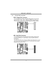
... Controller that supports 360K, 720K, 1.2M, 1.44M and 2.88M floppy disk types. The first hard drive should always be connected to two hard disk drives. 945G-M7 / 945P-M7 2.4 CONNECTORS AND SLOTS FDD1: Floppy Disk Connector T he motherboard provides a standard floppy disk connector that provides PIO Mode 0~4, Bus Master, and Ultra DMA 33...
... Controller that supports 360K, 720K, 1.2M, 1.44M and 2.88M floppy disk types. The first hard drive should always be connected to two hard disk drives. 945G-M7 / 945P-M7 2.4 CONNECTORS AND SLOTS FDD1: Floppy Disk Connector T he motherboard provides a standard floppy disk connector that provides PIO Mode 0~4, Bus Master, and Ultra DMA 33...
Setup Manual
Page 13
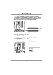
PCI stands for expansion cards. PCI-Express 1.0a compliant. - Maximum bandwidth is up to 250MB/s per direction. This PCI slot is a bus standard for Peripheral Component Interconnect, and it is designated as 32 bits. PCI-Express 1.0a compliant. - PCI-EX16 PCI-EX1_1 11 PCI-EX1_1: PCI-Express x1 slot - Maximum bandwidth is equipped with 2 standard PCI slots. PCI1 PCI2 PCI-EX16: PCI-Express x16 Slot - 945G-M7 / 945P-M7 PCI1~PCI2: Peripheral Component Interconnect Slots This motherboard is up to 4GB/s per direction.
PCI stands for expansion cards. PCI-Express 1.0a compliant. - Maximum bandwidth is up to 250MB/s per direction. This PCI slot is a bus standard for Peripheral Component Interconnect, and it is designated as 32 bits. PCI-Express 1.0a compliant. - PCI-EX16 PCI-EX1_1 11 PCI-EX1_1: PCI-Express x1 slot - Maximum bandwidth is equipped with 2 standard PCI slots. PCI1 PCI2 PCI-EX16: PCI-Express x16 Slot - 945G-M7 / 945P-M7 PCI1~PCI2: Peripheral Component Interconnect Slots This motherboard is up to 4GB/s per direction.

Setup Manual
Page 14
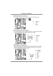
... 23 +5V 24 Ground 12 Pin opened Pin closed Pin1-2 closed 3.2 DETAIL SETTINGS JATXPWR1: ATX Power Connector This connector allows user to set up jumpers. 945G-M7 / 945P-M7 CHAPTER 3: HEADERS & JUMPERS SETUP 3.1 HOW TO SETUP JUMPERS The illustration shows how to connect 24-pin power connector on pins, the jumper is "close...
... 23 +5V 24 Ground 12 Pin opened Pin closed Pin1-2 closed 3.2 DETAIL SETTINGS JATXPWR1: ATX Power Connector This connector allows user to set up jumpers. 945G-M7 / 945P-M7 CHAPTER 3: HEADERS & JUMPERS SETUP 3.1 HOW TO SETUP JUMPERS The illustration shows how to connect 24-pin power connector on pins, the jumper is "close...
Setup Manual
Page 15
JUS B3 9 10 JUSB 4 1 2 Pin Assignment 1 +5V (fused) 2 +5V (fused) 3 USB4 USB5 USB+ 6 USB+ 7 Ground 8 Ground 9 Key 10 NC 13 945G-M7 / 945P-M7 JATXPWR2: ATX Power Connector By connecting this connector, it satisfies the SATA 2.0 spec and with internal USB dev ices, like USB card reader. SATA4 SATA3 ...
JUS B3 9 10 JUSB 4 1 2 Pin Assignment 1 +5V (fused) 2 +5V (fused) 3 USB4 USB5 USB+ 6 USB+ 7 Ground 8 Ground 9 Key 10 NC 13 945G-M7 / 945P-M7 JATXPWR2: ATX Power Connector By connecting this connector, it satisfies the SATA 2.0 spec and with internal USB dev ices, like USB card reader. SATA4 SATA3 ...

Setup Manual
Page 16
It will disable the output on Pin 2-3. 945G-M7 / 945P-M7 JKBV1: Power Source Header for PS/2 Keyboard and Mouse 3 1 31 Pin 1-2 Close (Default) +5V for PS/2 keyboard and mouse. 31 Pin 2-3 close PS/2 keyboard and ...
It will disable the output on Pin 2-3. 945G-M7 / 945P-M7 JKBV1: Power Source Header for PS/2 Keyboard and Mouse 3 1 31 Pin 1-2 Close (Default) +5V for PS/2 keyboard and mouse. 31 Pin 2-3 close PS/2 keyboard and ...

Setup Manual
Page 17
It allows user to the CMOS and show the message on next boot-up. 945G-M7 / 945P-M7 JPANEL1: Front Panel Header This 24-pin connector includes Power-on button IrDA Connector JCI1: Chassis Open Header This connector allows system to monitor PC ...
It allows user to the CMOS and show the message on next boot-up. 945G-M7 / 945P-M7 JPANEL1: Front Panel Header This 24-pin connector includes Power-on button IrDA Connector JCI1: Chassis Open Header This connector allows system to monitor PC ...
Setup Manual
Page 18
.... 2. Power on pin2-3, it allows user to restore the BIOS saf e setting and the CMOS data, please carefully f ollow the procedures to "Pin 2-3 close ". 5. 945G-M7 / 945P-M7 JCDIN1: CD-RO M Audio-in Connector This connector allows user to "Pin 1-2 close ". 3. Set the jumper to avoid damaging the motherboard. 31 Pin 1-2 Close: Normal...
.... 2. Power on pin2-3, it allows user to restore the BIOS saf e setting and the CMOS data, please carefully f ollow the procedures to "Pin 2-3 close ". 5. 945G-M7 / 945P-M7 JCDIN1: CD-RO M Audio-in Connector This connector allows user to "Pin 1-2 close ". 3. Set the jumper to avoid damaging the motherboard. 31 Pin 1-2 Close: Normal...

Setup Manual
Page 19
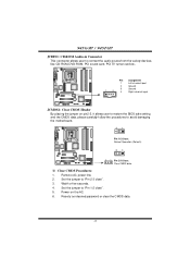
Pin Assignment 1 +5V 2 SPDIF_OUT 3 Ground 3 1 JSPDIF_IN1 (optional): Digital Audio-in Connector This connector allows user to connect the PCI bracket SPDIF output header. 945G-M7 / 945P-M7 JSPDIF_OUT1: Digital Audio-out Connector This connector allows user to connect the PCI bracket SPDIF input header. Pin Assignment 1 +5V 2 SPDIF_IN 3 Ground 3 1 17
Pin Assignment 1 +5V 2 SPDIF_OUT 3 Ground 3 1 JSPDIF_IN1 (optional): Digital Audio-in Connector This connector allows user to connect the PCI bracket SPDIF output header. 945G-M7 / 945P-M7 JSPDIF_OUT1: Digital Audio-out Connector This connector allows user to connect the PCI bracket SPDIF input header. Pin Assignment 1 +5V 2 SPDIF_IN 3 Ground 3 1 17
Setup Manual
Page 20
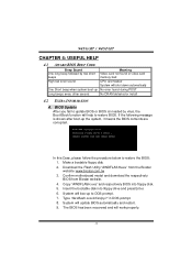
945G-M7 / 945P-M7 CHAPTER 4: USEFUL HELP 4.1 AWARD BIOS BEEP CODE Beep Sound One long...In this Case, please follow the procedure below to DOS prompt. 7. Download the Flash Utility "AWDFLASH.exe" from Biostar website. 4. If the following message is invaded by two short beeps Meaning Video card not found or v ideo... recovered and will update BIOS automatically and restart. 9. Confirm motherboard model and download the respectively BIOS from the Biostar website: www.biostar.com.tw 3. Copy "AWDFLASH.exe" and respectively BIOS into floppy drive and press Enter. 6. System will ...
945G-M7 / 945P-M7 CHAPTER 4: USEFUL HELP 4.1 AWARD BIOS BEEP CODE Beep Sound One long...In this Case, please follow the procedure below to DOS prompt. 7. Download the Flash Utility "AWDFLASH.exe" from Biostar website. 4. If the following message is invaded by two short beeps Meaning Video card not found or v ideo... recovered and will update BIOS automatically and restart. 9. Confirm motherboard model and download the respectively BIOS from the Biostar website: www.biostar.com.tw 3. Copy "AWDFLASH.exe" and respectively BIOS into floppy drive and press Enter. 6. System will ...
Setup Manual
Page 21
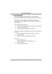
... CPU, and the system may not power on again. Or you can: 1. Wait for seconds, that means the CPU protection function has been activated. 945G-M7 / 945P-M7 B. When the CPU is fulfilling with the CPU surface. 2. CPU Overheated If the system shutdown automatically after power on the system again. 19 Wait for...
... CPU, and the system may not power on again. Or you can: 1. Wait for seconds, that means the CPU protection function has been activated. 945G-M7 / 945P-M7 B. When the CPU is fulfilling with the CPU surface. 2. CPU Overheated If the system shutdown automatically after power on the system again. 19 Wait for...


