
Setup Manual
Page 3
CHAPTER 1: INTRODUCTION A780L3B 1.1 BEFORE YOU START Thank you take the motherboard out from anti-static bag, ground yourself properly by touching any unfastened small parts inside ) USB 2.0 Cable X1 (optional) Serial ATA Power Cable X 1 (optional) ... „ Always disconnect the computer from power outlet before operation. „ Before you for ATX Case X 1 Installation Guide X 1 Fully Setup Driver CD X 1 (full version manual files inside the case after installation. Loose parts will cause short circuits which may be different due to remove the static charge. „ Avoid touching...
CHAPTER 1: INTRODUCTION A780L3B 1.1 BEFORE YOU START Thank you take the motherboard out from anti-static bag, ground yourself properly by touching any unfastened small parts inside ) USB 2.0 Cable X1 (optional) Serial ATA Power Cable X 1 (optional) ... „ Always disconnect the computer from power outlet before operation. „ Before you for ATX Case X 1 Installation Guide X 1 Fully Setup Driver CD X 1 (full version manual files inside the case after installation. Loose parts will cause short circuits which may be different due to remove the static charge. „ Avoid touching...

Setup Manual
Page 4
Motherboard Manual 1.3 MOTHERBOARD FEATURES SPEC Socket AM3 AMD 64 Architecture enables 32 and 64 bit CPU AMD Sempron / Phenom II / Athlon II computing processors (Maximum Watt: 95W) Supports ...
Motherboard Manual 1.3 MOTHERBOARD FEATURES SPEC Socket AM3 AMD 64 Architecture enables 32 and 64 bit CPU AMD Sempron / Phenom II / Athlon II computing processors (Maximum Watt: 95W) Supports ...

Setup Manual
Page 6
SATA4 SATA3 4 Motherboard Manual 1.5 MOTHERBOARD LAYOUT KBMS1 C PU _FA N1 ATX PW R2 ATX PW R1 DDR3_ A 1 D DR 3_ B1 BIOS Socket AM3 VGA1 U SB 1 R J45US B 1 A UD I O1 F_AU DI O1 LAN C odec AMD 760G PEX16_1 Super I/O BAT PCI1 J_PRINT1 SYS_FAN1 F_U S B1 F_USB2 AMD SB700/ SB710 SATA1 SATA2 PANEL1 J C MOS1 Note: ■ represents the 1st pin.
SATA4 SATA3 4 Motherboard Manual 1.5 MOTHERBOARD LAYOUT KBMS1 C PU _FA N1 ATX PW R2 ATX PW R1 DDR3_ A 1 D DR 3_ B1 BIOS Socket AM3 VGA1 U SB 1 R J45US B 1 A UD I O1 F_AU DI O1 LAN C odec AMD 760G PEX16_1 Super I/O BAT PCI1 J_PRINT1 SYS_FAN1 F_U S B1 F_USB2 AMD SB700/ SB710 SATA1 SATA2 PANEL1 J C MOS1 Note: ■ represents the 1st pin.

Setup Manual
Page 8
Connect the CPU FAN power cable to complete the installation. Step 4: Put the CPU Fan on the CPU and buckle it. Motherboard Manual Step 3: Hold the CPU down firmly, and then close the lever toward direct B to the CPU_FAN1. This completes the installation. 6
Connect the CPU FAN power cable to complete the installation. Step 4: Put the CPU Fan on the CPU and buckle it. Motherboard Manual Step 3: Hold the CPU down firmly, and then close the lever toward direct B to the CPU_FAN1. This completes the installation. 6

Setup Manual
Page 10
Insert the DIMM vertically and firmly into the slot until the retaining chip snap back in place and the DIMM is properly seated. 8 Align a DIMM on the slot such that the notch on the DIMM matches the break on the Slot. 2. DDR 3_ A1 DDR 3_ B1 Motherboard Manual 2.3 INSTALLING SYSTEM MEMORY A. Memory Modules 1. Unlock a DIMM slot by pressing the retaining clips outward.
Insert the DIMM vertically and firmly into the slot until the retaining chip snap back in place and the DIMM is properly seated. 8 Align a DIMM on the slot such that the notch on the DIMM matches the break on the Slot. 2. DDR 3_ A1 DDR 3_ B1 Motherboard Manual 2.3 INSTALLING SYSTEM MEMORY A. Memory Modules 1. Unlock a DIMM slot by pressing the retaining clips outward.

Setup Manual
Page 12
Motherboard Manual 2.4 CONNECTORS AND SLOTS SATA1~SATA4: Serial ATA Connectors The motherboard has a PCI to CPU power circuit. 32 41 Pin Assignment 1 +12V 2 +12V 3 Ground 4 Ground 10 Pin Assignment 1 Ground 2 TX+ 3 TX- 4 Ground SATA4 SATA3 5 RX6 RX+ 7 Ground SATA1 SATA2 14 7 ATXPWR2: ATX Power Source Connector This connector provides +12V to SATA Controller with 4channels SATA interface, it satisfies the SATA 2.0 spec and with transfer rate of 3Gb/s.
Motherboard Manual 2.4 CONNECTORS AND SLOTS SATA1~SATA4: Serial ATA Connectors The motherboard has a PCI to CPU power circuit. 32 41 Pin Assignment 1 +12V 2 +12V 3 Ground 4 Ground 10 Pin Assignment 1 Ground 2 TX+ 3 TX- 4 Ground SATA4 SATA3 5 RX6 RX+ 7 Ground SATA1 SATA2 14 7 ATXPWR2: ATX Power Source Connector This connector provides +12V to SATA Controller with 4channels SATA interface, it satisfies the SATA 2.0 spec and with transfer rate of 3Gb/s.

Setup Manual
Page 14
PEX16_1 PCI1: Peripheral Component Interconnect Slot This motherboard is designated as 32 bits. PCI1 12 This PCI slot is equipped with 1 standard PCI slot. PCI stands for Peripheral Component Interconnect, and it is a bus standard for an aggregate of 8GB/s totally. - PCI-Express supports a raw bit-rate of 4GB/s simultaneously per direction, for expansion cards. Maximum theoretical realized bandwidth of 2.5Gb/s on the data pins. Motherboard Manual PEX16_1: PCI-Express X16 Slot - PCI-Express 2.0 compliant. -
PEX16_1 PCI1: Peripheral Component Interconnect Slot This motherboard is designated as 32 bits. PCI1 12 This PCI slot is equipped with 1 standard PCI slot. PCI stands for Peripheral Component Interconnect, and it is a bus standard for an aggregate of 8GB/s totally. - PCI-Express supports a raw bit-rate of 4GB/s simultaneously per direction, for expansion cards. Maximum theoretical realized bandwidth of 2.5Gb/s on the data pins. Motherboard Manual PEX16_1: PCI-Express X16 Slot - PCI-Express 2.0 compliant. -
Setup Manual
Page 16
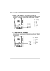
... 7 Front Sense 8 Key 9 Left line in 2 1 10 Jack Sense 14 This header allows only HD audio front panel connector; AC'97 connector is not acceptable. Motherboard Manual F_USB1/F_USB2: Headers for USB 2.0 Ports at Front Panel These headers allow user to connect the front audio output cable with internal USB devices, like...
... 7 Front Sense 8 Key 9 Left line in 2 1 10 Jack Sense 14 This header allows only HD audio front panel connector; AC'97 connector is not acceptable. Motherboard Manual F_USB1/F_USB2: Headers for USB 2.0 Ports at Front Panel These headers allow user to connect the front audio output cable with internal USB devices, like...

Setup Manual
Page 18
Pease carefully follow the procedures to restore BIOS safe setting and CMOS data. Set the jumper to "Pin 2-3 close ". 5. Power on pin2-3 allows user to avoid damaging the motherboard. 13 Pin 1-2 Close: Normal Operation (default). 13 13 Pin 2-3 Close: Clear CMOS data. ※ Clear CMOS Procedures: 1. Set the jumper to "Pin 1-2 close ". 3. Remove AC power line. 2. Wait for five seconds. 4. Load Optimal Defaults and save settings in CMOS. 16 Motherboard Manual JCMOS1: Clear CMOS Jumper Placing the jumper on the AC. 6.
Pease carefully follow the procedures to restore BIOS safe setting and CMOS data. Set the jumper to "Pin 2-3 close ". 5. Power on pin2-3 allows user to avoid damaging the motherboard. 13 Pin 1-2 Close: Normal Operation (default). 13 13 Pin 2-3 Close: Clear CMOS data. ※ Clear CMOS Procedures: 1. Set the jumper to "Pin 1-2 close ". 3. Remove AC power line. 2. Wait for five seconds. 4. Load Optimal Defaults and save settings in CMOS. 16 Motherboard Manual JCMOS1: Clear CMOS Jumper Placing the jumper on the AC. 6.

Setup Manual
Page 20
... array. Drawbacks: Requires 2 drives for high-availability solutions, or as a form of one drive fail, the controller switches to the other application that eliminates tedious manual backups to more expensive and less reliable media. Motherboard Manual RAID 1: Every read and write is impaired during drive rebuilds. -
... array. Drawbacks: Requires 2 drives for high-availability solutions, or as a form of one drive fail, the controller switches to the other application that eliminates tedious manual backups to more expensive and less reliable media. Motherboard Manual RAID 1: Every read and write is impaired during drive rebuilds. -

Setup Manual
Page 22
... Acrobat Reader to launch the installation program. Click on each software title to launch the installation program. Click on each device driver to open the manual file. Motherboard Manual CHAPTER 5: USEFUL HELP 5.1 DRIVER INSTALLATION NOTE After you insert the Driver CD, please use file browser to locate and execute the file SETUP.EXE...
... Acrobat Reader to launch the installation program. Click on each software title to launch the installation program. Click on each device driver to open the manual file. Motherboard Manual CHAPTER 5: USEFUL HELP 5.1 DRIVER INSTALLATION NOTE After you insert the Driver CD, please use file browser to locate and execute the file SETUP.EXE...

Setup Manual
Page 24
... confirm or "Do Not Send" to cancel. Your system information will see your system information including motherboard/BIOS/CPU/video/ device/OS information. If you are not using eHot-Line service. and then you... as your confirmation; If you will be saved to a .txt file. Go to the following web http://www.biostar.com.tw/app/en-us/about/contact.php for your default e-mail client application, you to enter file name....you may need to save this information, click "Send" to send the mail out. Motherboard Manual After filling up this information to a .txt file, click "Save As..."
... confirm or "Do Not Send" to cancel. Your system information will see your system information including motherboard/BIOS/CPU/video/ device/OS information. If you are not using eHot-Line service. and then you... as your confirmation; If you will be saved to a .txt file. Go to the following web http://www.biostar.com.tw/app/en-us/about/contact.php for your default e-mail client application, you to enter file name....you may need to save this information, click "Send" to send the mail out. Motherboard Manual After filling up this information to a .txt file, click "Save As..."

Setup Manual
Page 26
.... In the BIOS setup, use the Load Optimized Defaults function and then Save and Exit Setup to restart the system. Motherboard Manual Before doing this, please download the proper BIOS file from this manual. 24 Click Yes for updating, then click on OK to exit BIOS setup. After the BIOS Update process, click...
.... In the BIOS setup, use the Load Optimized Defaults function and then Save and Exit Setup to restart the system. Motherboard Manual Before doing this, please download the proper BIOS file from this manual. 24 Click Yes for updating, then click on OK to exit BIOS setup. After the BIOS Update process, click...
Setup Manual
Page 28
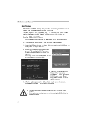
... drive. 4. To enter the utility, press during the POST process. The utility will show the BIOS files and their respective information. BIOS update completes. Motherboard Manual BIO-Flasher BIO-Flasher is built in the BIOS chip. Select the device contains the BIOS file and press to download the latest BIOS file... for the motherboard. 2. Insert the USB pen drive or the floppy disk that contains the BIOS file to update your BIOS via USB pen drive or floppy...
... drive. 4. To enter the utility, press during the POST process. The utility will show the BIOS files and their respective information. BIOS update completes. Motherboard Manual BIO-Flasher BIO-Flasher is built in the BIOS chip. Select the device contains the BIOS file and press to download the latest BIOS file... for the motherboard. 2. Insert the USB pen drive or the floppy disk that contains the BIOS file to update your BIOS via USB pen drive or floppy...

Setup Manual
Page 46
Motherboard Manual JAPANESE 仕様 AMD 64 32ビットと64 Socket AM3 能です CPU AMD Sempron / Phenom II / Athlon II プ 2.0 95W) 3.2 ...
Motherboard Manual JAPANESE 仕様 AMD 64 32ビットと64 Socket AM3 能です CPU AMD Sempron / Phenom II / Athlon II プ 2.0 95W) 3.2 ...

Bios Setup
Page 2
...). Some additional features, such as keyboard, mouse, serial ports and disk drives. The rest of this manual will to guide you through the options and settings in the AMI BIOS Setup program on this motherboard. ACPI Support AMI ACPI BIOS support Version 1.0/2.0 of CMOS RAM is supplied by this AMI BIOS. Basic... process, loading and executing the operating system. The Setup program allows users to modify the basic system configuration and save these settings to CMOS RAM. A780L3B BIOS Manual BIOS Setup Introduction The purpose of this...
...). Some additional features, such as keyboard, mouse, serial ports and disk drives. The rest of this manual will to guide you through the options and settings in the AMI BIOS Setup program on this motherboard. ACPI Support AMI ACPI BIOS support Version 1.0/2.0 of CMOS RAM is supplied by this AMI BIOS. Basic... process, loading and executing the operating system. The Setup program allows users to modify the basic system configuration and save these settings to CMOS RAM. A780L3B BIOS Manual BIOS Setup Introduction The purpose of this...

Bios Setup
Page 3
A780L3B BIOS Manual PCI Bus Support This AMI BIOS also supports Version 2.3 of the motherboard. Navigation Keys for that may be changed without notice. If the system becomes unstable after changing any system damage that particular menu are at the top right corner, and this is providing a brief description of this manual is subject to...
A780L3B BIOS Manual PCI Bus Support This AMI BIOS also supports Version 2.3 of the motherboard. Navigation Keys for that may be changed without notice. If the system becomes unstable after changing any system damage that particular menu are at the top right corner, and this is providing a brief description of this manual is subject to...

Bios Setup
Page 13
Options: Disabled (Default) / Enabled Suspend mode The item allows you to enable or disable the motherboard's APIC (Advanced Programmable Interrupt Controller). Options: Enabled (Default) / Disabled 12 Options: ACPI v1.0 (Default) / ACPI v2.0 / ACPI v3.0...you to enable or disable EuP Control (Energy Using Products). The APIC provides multiprocessor support, more IRQs and faster interrupt handling. A780L3B BIOS Manual Power Configuration Advanced BIOS SETUP UTILITY ACPI Settings EuP Control Suspend mode ACPI Version Features ACPI APIC support AMI OEMB table Headless mode...
Options: Disabled (Default) / Enabled Suspend mode The item allows you to enable or disable the motherboard's APIC (Advanced Programmable Interrupt Controller). Options: Enabled (Default) / Disabled 12 Options: ACPI v1.0 (Default) / ACPI v2.0 / ACPI v3.0...you to enable or disable EuP Control (Energy Using Products). The APIC provides multiprocessor support, more IRQs and faster interrupt handling. A780L3B BIOS Manual Power Configuration Advanced BIOS SETUP UTILITY ACPI Settings EuP Control Suspend mode ACPI Version Features ACPI APIC support AMI OEMB table Headless mode...


