Specifications Sheet
Page 2
... adjustable cut-off frequency s Ultra-low noise microphone pre amp with 60 dB gain control and +48 V phantom power s Level conversion from line to microphone level and vice versa s Status LED's for all 12 filters s Two 24-bit A/D and D/A converters s Servo-balanced inputs and outputs with XLR and 1/4" phone connectors s Rugged external power supply for maximum signal integrity and headroom s 6-segment clip level meter with clipping indicator s 4-digit multi-function display...
... adjustable cut-off frequency s Ultra-low noise microphone pre amp with 60 dB gain control and +48 V phantom power s Level conversion from line to microphone level and vice versa s Status LED's for all 12 filters s Two 24-bit A/D and D/A converters s Servo-balanced inputs and outputs with XLR and 1/4" phone connectors s Rugged external power supply for maximum signal integrity and headroom s 6-segment clip level meter with clipping indicator s 4-digit multi-function display...
Manual
Page 2
... of time. The power supply cord or the plug has been damaged; or - or - This symbol, wherever it appears, alerts you to the presence of uninsulated dangerous voltage inside ; Read the manual. Non-use Periods: The power cord of the...user serviceable parts inside the enclosure - Power Source: The appliance should be connected to important operating and maintenance instructions in the operating instructions should be unplugged from heat sources such as marked on the appliance and in the accompanying literature. Retain Instructions: The safety and operating instructions...
... of time. The power supply cord or the plug has been damaged; or - or - This symbol, wherever it appears, alerts you to the presence of uninsulated dangerous voltage inside ; Read the manual. Non-use Periods: The power cord of the...user serviceable parts inside the enclosure - Power Source: The appliance should be connected to important operating and maintenance instructions in the operating instructions should be unplugged from heat sources such as marked on the appliance and in the accompanying literature. Retain Instructions: The safety and operating instructions...
Manual
Page 3
... meter), a ULN (Ultra-Low Noise) microphone pre-amp with graphic equalizers, or to assign this task to a multi-channel system using the ingenious search algorithms of our FEEDBACK DESTROYER PRO DSP1124P, a variable Delay Line (adjustable in BEHRINGER products by purchasing the SHARK DSP110. + This manual first describes the terminology used, so that you can fully understand the DSP110 and its functions. Using extremely narrow-bandwidth filters, the SHARK DSP110 eliminates only unwanted...
... meter), a ULN (Ultra-Low Noise) microphone pre-amp with graphic equalizers, or to assign this task to a multi-channel system using the ingenious search algorithms of our FEEDBACK DESTROYER PRO DSP1124P, a variable Delay Line (adjustable in BEHRINGER products by purchasing the SHARK DSP110. + This manual first describes the terminology used, so that you can fully understand the DSP110 and its functions. Using extremely narrow-bandwidth filters, the SHARK DSP110 eliminates only unwanted...
Manual
Page 5
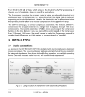
... maximum interference immunity. to the mains. Please use the enclosed power supply to connect the unit to avoid overheating. As a standard the audio inputs and outputs of the BEHRINGER SHARK DSP110 are fully balanced. If possible, connect the unit to other devices in chapter 3 “INSTALLATION”. The automatic servo function detects unbalanced connections and compensates the level difference automatically (6 dB correction). 1. Further information can...
... maximum interference immunity. to the mains. Please use the enclosed power supply to connect the unit to avoid overheating. As a standard the audio inputs and outputs of the BEHRINGER SHARK DSP110 are fully balanced. If possible, connect the unit to other devices in chapter 3 “INSTALLATION”. The automatic servo function detects unbalanced connections and compensates the level difference automatically (6 dB correction). 1. Further information can...
Manual
Page 6
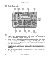
... be adjusted on the display . 6 1. If gain is driven correctly. The CLIP LEVEL control does not affect the input/output levels, but adapts the audio signal as optimally as possible to the digital circuitry. The CLIP LEVEL control lets you can be made with the CLIP LEVEL control . INTRODUCTION These five LEDs symbolize the units of the parameters that the CLIP LED won’t light...
... be adjusted on the display . 6 1. If gain is driven correctly. The CLIP LEVEL control does not affect the input/output levels, but adapts the audio signal as optimally as possible to the digital circuitry. The CLIP LEVEL control lets you can be made with the CLIP LEVEL control . INTRODUCTION These five LEDs symbolize the units of the parameters that the CLIP LED won’t light...
Manual
Page 7
... in use. s Free filters which can use the DELAY function. To speed up while you are using high values, the 4-digit display reads the last figure only when you start editing with the ACTIVE button). When a filter is not lit. The control LED lights up the selection, briefly press the key located next to either choose msec, feet or meter. The setting range is...
... in use. s Free filters which can use the DELAY function. To speed up while you are using high values, the 4-digit display reads the last figure only when you start editing with the ACTIVE button). When a filter is not lit. The control LED lights up the selection, briefly press the key located next to either choose msec, feet or meter. The setting range is...
Manual
Page 8
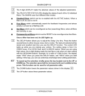
... control LED lights up while you adapt the DSP110’s Compressor function to OFF the filter is 50. Pressing the GATE button for feedback frequencies and assigns free filters to the frequencies found. Press the button once to adjust ...program material and adjusting the value accordingly (value detected plus 2 dB). Although the remaining filters are also used for a longer time (please wait, until all five parameter LEDs light up as soon as the LED flashes, the detected value is read on the display, when the LED stops flashing, the value is enabled, the LOW CUT key’s control...
... control LED lights up while you adapt the DSP110’s Compressor function to OFF the filter is 50. Pressing the GATE button for feedback frequencies and assigns free filters to the frequencies found. Press the button once to adjust ...program material and adjusting the value accordingly (value detected plus 2 dB). Although the remaining filters are also used for a longer time (please wait, until all five parameter LEDs light up as soon as the LED flashes, the detected value is read on the display, when the LED stops flashing, the value is enabled, the LOW CUT key’s control...
Manual
Page 9
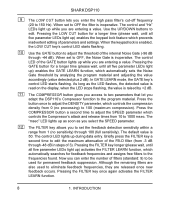
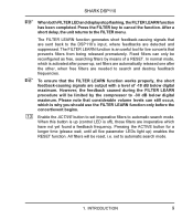
SHARK DSP110 + When both FILTER LED and display stop flashing, the FILTER LEARN function has been completed. All filters will be limited by means of -18 dB below digital maximum. INTRODUCTION 9 Please note that the FILTER LEARN function works properly, the short feedback-causing signals are output with a level of a RESET. To ensure that considerable volume levels can only be reset, i.e. When this button is up (control LED...
SHARK DSP110 + When both FILTER LED and display stop flashing, the FILTER LEARN function has been completed. All filters will be limited by means of -18 dB below digital maximum. INTRODUCTION 9 Please note that the FILTER LEARN function works properly, the short feedback-causing signals are output with a level of a RESET. To ensure that considerable volume levels can only be reset, i.e. When this button is up (control LED...
Manual
Page 10
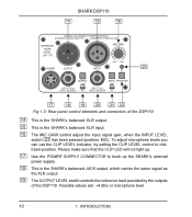
... light up. 17 Use the POWER SUPPLY CONNECTOR to midtravel position. SHARK DSP110 Fig 1.3: Rear panel control elements and connectors of the DSP110. To adjust microphone levels you can use the CLIP LEVEL indicator, by the outputs of the DSP110 14 This is the SHARK’s balanced XLR output. 15 This is the SHARK’s balanced JACK output, which carries the same signal as the XLR output. 19 The OUTPUT LEVEL switch controls the reference level provided by setting the CLIP LEVEL control...
... light up. 17 Use the POWER SUPPLY CONNECTOR to midtravel position. SHARK DSP110 Fig 1.3: Rear panel control elements and connectors of the DSP110. To adjust microphone levels you can use the CLIP LEVEL indicator, by the outputs of the DSP110 14 This is the SHARK’s balanced XLR output. 15 This is the SHARK’s balanced JACK output, which carries the same signal as the XLR output. 19 The OUTPUT LEVEL switch controls the reference level provided by setting the CLIP LEVEL control...
Manual
Page 11
... the output signal of applications. Switch on . 2. We therefore recommend that the CLIP-LED will not light up when Phantom Power is on Phantom Power when you can set to protect specific single microphones against feedback. SHARK DSP110 20 This is the SHARK’s balanced JACK input, which is wired in use the CLIP LEVEL control to adapt the internal level settings to the digital circuitry. In LINE mode, you can use , you connect the SHARK between microphone...
... the output signal of applications. Switch on . 2. We therefore recommend that the CLIP-LED will not light up when Phantom Power is on Phantom Power when you can set to protect specific single microphones against feedback. SHARK DSP110 20 This is the SHARK’s balanced JACK input, which is wired in use the CLIP LEVEL control to adapt the internal level settings to the digital circuitry. In LINE mode, you can use , you connect the SHARK between microphone...
Manual
Page 13
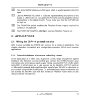
APPLICATIONS 13 Fig. 2.3: The SHARK connected between the console’s output and the input of the power amp driving the “delayed” speakers. SHARK DSP110 2.1.3 Connection between mixing console and power amplifier When you use the SHARK as a Delay Line unit for speaker systems placed at various positions (see chapter 2.3), you should connect the SHARK between console and power amp 2.
APPLICATIONS 13 Fig. 2.3: The SHARK connected between the console’s output and the input of the power amp driving the “delayed” speakers. SHARK DSP110 2.1.3 Connection between mixing console and power amplifier When you use the SHARK as a Delay Line unit for speaker systems placed at various positions (see chapter 2.3), you should connect the SHARK between console and power amp 2.
Manual
Page 14
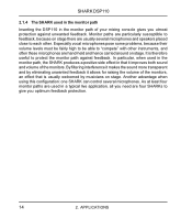
... the sound more transparent and by musicians on stage. Especially vocal microphones pose some problems, because their volume levels must be fairly high to be able to feedback, because on stage. APPLICATIONS As at least four monitor paths are particularly susceptible to “compete” with other . SHARK DSP110 2.1.4 The SHARK used in the monitor path Inserting the DSP110 in the monitor path...
... the sound more transparent and by musicians on stage. Especially vocal microphones pose some problems, because their volume levels must be fairly high to be able to feedback, because on stage. APPLICATIONS As at least four monitor paths are particularly susceptible to “compete” with other . SHARK DSP110 2.1.4 The SHARK used in the monitor path Inserting the DSP110 in the monitor path...
Manual
Page 16
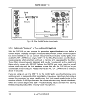
... “tuning in the monitors. The SHARK generates short feedbackcausing signals, which are using not just one DSP110 for the monitor path, you should employ some additional units to its input and suppressed by means of P.A. Please note that during a concert the musicians on your sound reinforcement system: once the system has been installed and set up, open all microphone channels and monitor paths...
... “tuning in the monitors. The SHARK generates short feedbackcausing signals, which are using not just one DSP110 for the monitor path, you should employ some additional units to its input and suppressed by means of P.A. Please note that during a concert the musicians on your sound reinforcement system: once the system has been installed and set up, open all microphone channels and monitor paths...

Manual
Page 17
... to the level of the overall signal. For speech-only applications you power up the SHARK). Whenever it is impossible from a physical point of view to distinguish wanted from unwanted feedback. hand-held vocal microphones) are moved during a performance (e.g. Thus, the SHARK makes sure that are usually susceptible to the frequency detected, this physical problem. 2. those used on how...
... to the level of the overall signal. For speech-only applications you power up the SHARK). Whenever it is impossible from a physical point of view to distinguish wanted from unwanted feedback. hand-held vocal microphones) are moved during a performance (e.g. Thus, the SHARK makes sure that are usually susceptible to the frequency detected, this physical problem. 2. those used on how...
Manual
Page 18
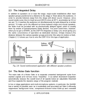
... dynamic range of the program material. Simply measure the distance between stage and remote speakers, the latter must be provided with an electronically delayed signal, which is to wire the DSP110 in this value (in order to provide listeners away from wanted signals and remove noise “inaudibly”. Fig. 2.6: Sound reinforcement application with direct sound. In live or stage applications and multi-microphone...
... dynamic range of the program material. Simply measure the distance between stage and remote speakers, the latter must be provided with an electronically delayed signal, which is to wire the DSP110 in this value (in order to provide listeners away from wanted signals and remove noise “inaudibly”. Fig. 2.6: Sound reinforcement application with direct sound. In live or stage applications and multi-microphone...
Manual
Page 19
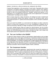
.../DOWN buttons can be used to fine-tune the Gate, until it is possible to feedback can also damage power amps and/or loudspeakers. During music pauses, however, the microphone picks up . Use the Gate function to reduce the signal level during music pauses. Basically, all stage microphones should be treated in this function before the concert and after the sound check. APPLICATIONS 19 The SHARK...
.../DOWN buttons can be used to fine-tune the Gate, until it is possible to feedback can also damage power amps and/or loudspeakers. During music pauses, however, the microphone picks up . Use the Gate function to reduce the signal level during music pauses. Basically, all stage microphones should be treated in this function before the concert and after the sound check. APPLICATIONS 19 The SHARK...
Manual
Page 20
... is installed with balanced connections 20 3. The first one, DENSITY, compresses the program material in broadcast, stage or recording applications. Use small values to make the Compressor respond to smallest level differences, and high values to adjust the Compressor function in the time domain. will be effectively suppressed. The DSP110 allows you can set to somewhere below the operating level to allow for trouble-free operation...
... is installed with balanced connections 20 3. The first one, DENSITY, compresses the program material in broadcast, stage or recording applications. Use small values to make the Compressor respond to smallest level differences, and high values to adjust the Compressor function in the time domain. will be effectively suppressed. The DSP110 allows you can set to somewhere below the operating level to allow for trouble-free operation...

Manual
Page 22
SPECIFICATIONS AUDIO INPUTS Connectors Type Impedance Nominal Operating Level Max. Output Level SYSTEM SPECIFICATIONS Frequency Response Noise THD DIGITAL PROCESSING Converters Sampling Rate DISPLAY Type POWER SUPPLY Mains Voltages PHYSICAL Dimensions (H * W * D) Net Weight XLR and 1/4" jack RF filtered, servo-balanced input 6 kOhms balanced, 3 kOhms unbalanced microphone or line level source (switchable) +19 dBu at microphone level and line level XLR and 1/4" jack electronically servo-balanced output stage 60 Ohms balanced, 30 Ohms unbalanced microphone level source or +4 dBu (...
SPECIFICATIONS AUDIO INPUTS Connectors Type Impedance Nominal Operating Level Max. Output Level SYSTEM SPECIFICATIONS Frequency Response Noise THD DIGITAL PROCESSING Converters Sampling Rate DISPLAY Type POWER SUPPLY Mains Voltages PHYSICAL Dimensions (H * W * D) Net Weight XLR and 1/4" jack RF filtered, servo-balanced input 6 kOhms balanced, 3 kOhms unbalanced microphone or line level source (switchable) +19 dBu at microphone level and line level XLR and 1/4" jack electronically servo-balanced output stage 60 Ohms balanced, 30 Ohms unbalanced microphone level source or +4 dBu (...
Manual
Page 25
... may subsequently purchase this manual is beyond the control of BEHRINGER Spezielle Studiotechnik GmbH. No part of the problem. ALL RIGHTS RESERVED. © 2001 BEHRINGER Spezielle Studiotechnik GmbH. BEHRINGER (BEHRINGER Spezielle Studiotechnik GmbH including all BEHRINGER subsidiaries listed on a national or local level, in its sole discretion, either repair or replace the product. 2. BEHRINGER Spezielle Studiotechnik GmbH, Hanns-Martin-Schleyer-Str. 36-38, 47877...
... may subsequently purchase this manual is beyond the control of BEHRINGER Spezielle Studiotechnik GmbH. No part of the problem. ALL RIGHTS RESERVED. © 2001 BEHRINGER Spezielle Studiotechnik GmbH. BEHRINGER (BEHRINGER Spezielle Studiotechnik GmbH including all BEHRINGER subsidiaries listed on a national or local level, in its sole discretion, either repair or replace the product. 2. BEHRINGER Spezielle Studiotechnik GmbH, Hanns-Martin-Schleyer-Str. 36-38, 47877...
Manual
Page 26
... 7647 SHARK DSP110 complies with the FCC rules as mentioned in a residential installation. This equipment generates, uses and can void the user's authority to correct the interference by MUSIC Group can radiate radio frequency energy and, if not installed and used in a particular installation. However, there is no guarantee that may cause harmful interference to part 15 of the FCC rules. Operation is connected...
... 7647 SHARK DSP110 complies with the FCC rules as mentioned in a residential installation. This equipment generates, uses and can void the user's authority to correct the interference by MUSIC Group can radiate radio frequency energy and, if not installed and used in a particular installation. However, there is no guarantee that may cause harmful interference to part 15 of the FCC rules. Operation is connected...


