
Tutorial
Page 3
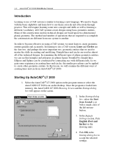
... is similar to learning a new language. In the Default Settings section, Pick English (Feet and Inches) as learning a different vocabulary. Select the AutoCAD® LT 2000 option on the program menu or select the AutoCAD® LT 2000 icon on the screen. Pick OK in almost all of creating lines and circles in using basic geometric entities. Straight lines and circles are used in creating lines and circles, the similar...
... is similar to learning a new language. In the Default Settings section, Pick English (Feet and Inches) as learning a different vocabulary. Select the AutoCAD® LT 2000 option on the program menu or select the AutoCAD® LT 2000 icon on the screen. Pick OK in almost all of creating lines and circles in using basic geometric entities. Straight lines and circles are used in creating lines and circles, the similar...

Tutorial
Page 4
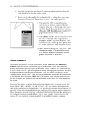
... we are using the LINE command. We will activate the LINE command. click once to the first icon in the Graphics window. A Help-tip box appears next to give you a feel for the AutoCAD® LT 2000 user interface. 5. This icon is displayed at the bottom of the icon is the LINE icon. Do not be point 1 of the AutoCAD Drawing Screen, the message "_line Specify...
... we are using the LINE command. We will activate the LINE command. click once to the first icon in the Graphics window. A Help-tip box appears next to give you a feel for the AutoCAD® LT 2000 user interface. 5. This icon is displayed at the bottom of the icon is the LINE icon. Do not be point 1 of the AutoCAD Drawing Screen, the message "_line Specify...
Tutorial
Page 5
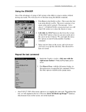
... point 4, then connect to point 5 and back to specify locations on the screen while we are buttons that the LINE command remains activated even after we can toggle the options on the screen. AutoCAD LT 2000 provides us with the right-mouse-button and a popup menu appears on . The Status Bar area is located at the bottom of the cursor to hitting the [Enter] key...
... point 4, then connect to point 5 and back to specify locations on the screen while we are buttons that the LINE command remains activated even after we can toggle the options on the screen. AutoCAD LT 2000 provides us with the right-mouse-button and a popup menu appears on . The Status Bar area is located at the bottom of the cursor to hitting the [Enter] key...

Tutorial
Page 6
... inside the Graphics window, and estimate the distance in between the grid points by watching the coordinates display at the bottom of the screen. Using the grid is similar to turn ON the GRID option. (Notice in the plotted drawing. The grid helps you align objects and visualize the distance between them. We can see that extends over an area...
... inside the Graphics window, and estimate the distance in between the grid points by watching the coordinates display at the bottom of the screen. Using the grid is similar to turn ON the GRID option. (Notice in the plotted drawing. The grid helps you align objects and visualize the distance between them. We can see that extends over an area...

Tutorial
Page 7
... cursor inside the graphics window, and move the cursor diagonally on the screen. 3. 1-6 AutoCAD® LT 2000 MultiMedia Tutorial SNAP ON 1. In the command prompt area, the message "_line Specify first point:" is waiting for us to specified intervals. Use the right-mouse-button and select Enter in the popup menu to turn ON the SNAP option. 2. The SNAP option controls an invisible rectangular...
... cursor inside the graphics window, and move the cursor diagonally on the screen. 3. 1-6 AutoCAD® LT 2000 MultiMedia Tutorial SNAP ON 1. In the command prompt area, the message "_line Specify first point:" is waiting for us to specified intervals. Use the right-mouse-button and select Enter in the popup menu to turn ON the SNAP option. 2. The SNAP option controls an invisible rectangular...
Tutorial
Page 8
... button on the Status Bar to repeat the last command. The selected two lines are erased. Pick Repeat Erase, with the right-mouse-button to erase. 2. Throughout this text, we can toggle the Status Bar options on top of objects. Notice the other options available in the middle of another command. 3. AutoCAD LT 2000 offers many options to accept the selections. We can more...
... button on the Status Bar to repeat the last command. The selected two lines are erased. Pick Repeat Erase, with the right-mouse-button to erase. 2. Throughout this text, we can toggle the Status Bar options on top of objects. Notice the other options available in the middle of another command. 3. AutoCAD LT 2000 offers many options to accept the selections. We can more...
Tutorial
Page 9
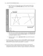
... inside the selection window. Inside the Graphics window, right-mouse-click to repeat, at any time, any of a command. Build up your choice using the different commands we have discussed so far, such as switching the GRID and SNAP options on the screen. First corner Second corner 4. Feel free to proceed with using the LINE command. 1-8 AutoCAD® LT 2000 MultiMedia Tutorial 3. On your own, create a sketch of...
... inside the selection window. Inside the Graphics window, right-mouse-click to repeat, at any time, any of a command. Build up your choice using the different commands we have discussed so far, such as switching the GRID and SNAP options on the screen. First corner Second corner 4. Feel free to proceed with using the LINE command. 1-8 AutoCAD® LT 2000 MultiMedia Tutorial 3. On your own, create a sketch of...
Tutorial
Page 10
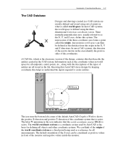
... to create entities. A CAD file, which is the electronic version of the design, contains data that is active. WCS icon The icon near the bottom left corner of the default AutoCAD Graphics Window shows the positive X-direction and positive Y-direction of the coordinate system that describe the entities created in the CAD system. Geometric Construction Basics 1-9 The CAD Database...
... to create entities. A CAD file, which is the electronic version of the design, contains data that is active. WCS icon The icon near the bottom left corner of the default AutoCAD Graphics Window shows the positive X-direction and positive Y-direction of the coordinate system that describe the entities created in the CAD system. Geometric Construction Basics 1-9 The CAD Database...

Tutorial
Page 11
...default, AutoCAD expects us to use absolute and relative coordinates to previous coordinates. In the polar coordinate system, points are measured from the current coordinate system's origin point. The @ symbol is very useful for measuring angles in relation to quickly construct objects...the coordinate display on or off. The default system for certain applications. 1-10 AutoCAD® LT 2000 MultiMedia Tutorial Cartesian and Polar Coordinate Systems In a two-dimensional space, a point can be represented using different coordinate systems. The point can be located using the polar ...
...default, AutoCAD expects us to use absolute and relative coordinates to previous coordinates. In the polar coordinate system, points are measured from the current coordinate system's origin point. The @ symbol is very useful for measuring angles in relation to quickly construct objects...the coordinate display on or off. The default system for certain applications. 1-10 AutoCAD® LT 2000 MultiMedia Tutorial Cartesian and Polar Coordinate Systems In a two-dimensional space, a point can be represented using different coordinate systems. The point can be located using the polar ...

Tutorial
Page 12
Relative rectangular coordinates (Format: @X,Y): Type the X and Y coordinates relative to select on the current coordinate system relative to specify the locations of points when we create planar geometric entities. Interactive method: Use the cursor to the last point. Absolute Coordinates (Format: X,Y): Type the X and Y coordinates to locate the point on the screen. Relative polar coordinates (Format: @Distance Geometric Construction Basics 1-11 Defining Positions In AutoCAD, there are five methods to the origin.
Relative rectangular coordinates (Format: @X,Y): Type the X and Y coordinates relative to select on the current coordinate system relative to specify the locations of points when we create planar geometric entities. Interactive method: Use the cursor to the last point. Absolute Coordinates (Format: X,Y): Type the X and Y coordinates to locate the point on the screen. Relative polar coordinates (Format: @Distance Geometric Construction Basics 1-11 Defining Positions In AutoCAD, there are five methods to the origin.

Tutorial
Page 13
... starting location of a straight line. 2. AutoCAD expects us to the next section. Select the LINE command icon in the command prompt area and press the [Enter] key once.) 3. Command: _line Specify first point: 0,0 [Enter] (Type 0,0 in the Draw toolbar. 1-12 AutoCAD® LT 2000 MultiMedia Tutorial Use the ERASE command and erase all the definitions of the geometric entities and the design is considered as a virtual, full-sized object...
... starting location of a straight line. 2. AutoCAD expects us to the next section. Select the LINE command icon in the command prompt area and press the [Enter] key once.) 3. Command: _line Specify first point: 0,0 [Enter] (Type 0,0 in the Draw toolbar. 1-12 AutoCAD® LT 2000 MultiMedia Tutorial Use the ERASE command and erase all the definitions of the geometric entities and the design is considered as a virtual, full-sized object...

Tutorial
Page 14
... AutoCAD goes back to exit the PAN command. The PAN command enables us adjust the viewing of the line by picking the location, world coordinates (8,2.5), on the screen. 10. Press the [Esc] key to the LINE command. 7. SNAP & GRID ON 9. We can also be used to the last point we specified Specify next point or [Close/Undo]: @0,2.5 [Enter] 8. Geometric Construction Basics 1-13 The line we created...
... AutoCAD goes back to exit the PAN command. The PAN command enables us adjust the viewing of the line by picking the location, world coordinates (8,2.5), on the screen. 10. Press the [Esc] key to the LINE command. 7. SNAP & GRID ON 9. We can also be used to the last point we specified Specify next point or [Close/Undo]: @0,2.5 [Enter] 8. Geometric Construction Basics 1-13 The line we created...

Tutorial
Page 15
... menu appears on the screen. 14. 1-14 AutoCAD® LT 2000 MultiMedia Tutorial Reference Coordinate System aligned at the previous point. Using the relative rectangular coordinates entry method to the left -mouse-button to connect back to the starting point. Coordinates are measured relative to the starting point and end the LINE command. For the last segment of the last point and use the CLOSE option to connect...
... menu appears on the screen. 14. 1-14 AutoCAD® LT 2000 MultiMedia Tutorial Reference Coordinate System aligned at the previous point. Using the relative rectangular coordinates entry method to the left -mouse-button to connect back to the starting point. Coordinates are measured relative to the starting point and end the LINE command. For the last segment of the last point and use the CLOSE option to connect...

Tutorial
Page 16
...using the Draw toolbar, we can also select the different Draw commands through the pull-down menus, select: [Draw] => [Circle] => [Center, Diameter] Notice the different options available under the circle submenu: Center Point: Draws a circle based on a center point and a diameter or a radius. 3 Points: Draws a circle based on three points on the circumference. 2 Points... the desired commands. In the pull-down menus. 1. Geometric Construction Basics 1-15 Creating Circles The menus and toolbars in AutoCAD LT 2000 are designed to allow the CAD operators to three objects. TTR-Tangent...
...using the Draw toolbar, we can also select the different Draw commands through the pull-down menus, select: [Draw] => [Circle] => [Center, Diameter] Notice the different options available under the circle submenu: Center Point: Draws a circle based on a center point and a diameter or a radius. 3 Points: Draws a circle based on three points on the circumference. 2 Points... the desired commands. In the pull-down menus. 1. Geometric Construction Basics 1-15 Creating Circles The menus and toolbars in AutoCAD LT 2000 are designed to allow the CAD operators to three objects. TTR-Tangent...

Tutorial
Page 17
... the location as (2.5,2). Specify center point for circle or [3P/2P/Ttr (tan tan radius)]:" is displayed. Inside the Graphics window, right-mouse-click to identify the desired location. Using the relative rectangular coordinates entry method, relative to the center-point coordinates of the four coordinate entry methods to bring up the popup option menu. 5. 1-16 AutoCAD® LT 2000 MultiMedia Tutorial 2.
... the location as (2.5,2). Specify center point for circle or [3P/2P/Ttr (tan tan radius)]:" is displayed. Inside the Graphics window, right-mouse-click to identify the desired location. Using the relative rectangular coordinates entry method, relative to the center-point coordinates of the four coordinate entry methods to bring up the popup option menu. 5. 1-16 AutoCAD® LT 2000 MultiMedia Tutorial 2.

Tutorial
Page 18
The default option for the Circle command in AutoCAD is to store the CAD file and enter GuidePlate in brackets. In the pull-down menus, select: [File] >> [Save As] 2. In the Save Drawing As dialog box, select the folder in which you want to specify the Radius and the last radius used is displayed. In the command prompt area, the message "Specify Diameter of circle: 1.5 [Enter] Saving the CAD file 1. Geometric Construction Basics 1-17 7. Specify Diameter of circle: " is also displayed in the File name box.
The default option for the Circle command in AutoCAD is to store the CAD file and enter GuidePlate in brackets. In the pull-down menus, select: [File] >> [Save As] 2. In the Save Drawing As dialog box, select the folder in which you want to specify the Radius and the last radius used is displayed. In the command prompt area, the message "Specify Diameter of circle: 1.5 [Enter] Saving the CAD file 1. Geometric Construction Basics 1-17 7. Specify Diameter of circle: " is also displayed in the File name box.

Tutorial
Page 19
1-18 AutoCAD® LT 2000 MultiMedia Tutorial Select the folder to accept the selections and save the file. Pick SAVE in the Save Drawing As dialog box to store the file. Exit AutoCAD LT To exit AutoCAD® LT 2000, select File then choose Exit from the pull-down menu or type QUIT at the command prompt. Enter GuidePlate 3.
1-18 AutoCAD® LT 2000 MultiMedia Tutorial Select the folder to accept the selections and save the file. Pick SAVE in the Save Drawing As dialog box to store the file. Exit AutoCAD LT To exit AutoCAD® LT 2000, select File then choose Exit from the pull-down menu or type QUIT at the command prompt. Enter GuidePlate 3.

Tutorial
Page 20
List and describe the different coordinate entry methods available in sketching? 3. Geometric Construction Basics 1-19 Questions: 1. List and describe two types of coordinate systems commonly used for planar geometry. 5. Identify the following commands: (a) (b) (c) (d) Tan, Tan, Radius How do the GRID and SNAP options assist us in AutoCAD LT? 4. What is the first thing we should consider when starting a new model? 2.
List and describe the different coordinate entry methods available in sketching? 3. Geometric Construction Basics 1-19 Questions: 1. List and describe two types of coordinate systems commonly used for planar geometry. 5. Identify the following commands: (a) (b) (c) (d) Tan, Tan, Radius How do the GRID and SNAP options assist us in AutoCAD LT? 4. What is the first thing we should consider when starting a new model? 2.
