
Owners Manual
Page 2
... of time during operation; Check under the vehicle to do so may result in the console becoming a projectile in the proper locations. Remove dust and stains with a built-in speaker, a built-in your vehicle which makes your vehicle's decor. This aesthetic console is a self-contained entertainment center in foil antenna, headphone jacks, AV input jacks, AV output jacks and a universal remote control. If...
... of time during operation; Check under the vehicle to do so may result in the console becoming a projectile in the proper locations. Remove dust and stains with a built-in speaker, a built-in your vehicle which makes your vehicle's decor. This aesthetic console is a self-contained entertainment center in foil antenna, headphone jacks, AV input jacks, AV output jacks and a universal remote control. If...

Owners Manual
Page 3
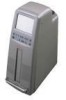
... TV reception. Auto Program Button 3. Play Button 13. Jack Cover 3 Figure 1 C. Power Button 8. Audio Right Input Jack 17. Speaker Holes 19. Cigarette Lighter Jack 22. Infrared Remote Control Sensor 7. Headphone Jack #1 14. Only use the supplied power cord, and not use it checked by pulling the cord. 10. Picture Button 2. Video Input Jack 15. Always unplug the unit from the unit connector by qualified personnel prior to further operation. 8. never disconnect the cable from the cigarette...
... TV reception. Auto Program Button 3. Play Button 13. Jack Cover 3 Figure 1 C. Power Button 8. Audio Right Input Jack 17. Speaker Holes 19. Cigarette Lighter Jack 22. Infrared Remote Control Sensor 7. Headphone Jack #1 14. Only use the supplied power cord, and not use it checked by pulling the cord. 10. Picture Button 2. Video Input Jack 15. Always unplug the unit from the unit connector by qualified personnel prior to further operation. 8. never disconnect the cable from the cigarette...

Owners Manual
Page 4
... the cardboard mounting template on an appropriate mounting location on the floor between driver/passenger seats, with the mounting plate on the floor over the drilled holes. 5. Contents in Kit TV and VCP Floor Console Owner's Manual Remote Control 12V Cigarette Lighter Cord and Plug (for powering this unit) Cardboard Mounting Template (for obstructions. 2. D. Make sure that you have checked both underneath...
... the cardboard mounting template on an appropriate mounting location on the floor between driver/passenger seats, with the mounting plate on the floor over the drilled holes. 5. Contents in Kit TV and VCP Floor Console Owner's Manual Remote Control 12V Cigarette Lighter Cord and Plug (for powering this unit) Cardboard Mounting Template (for obstructions. 2. D. Make sure that you have checked both underneath...

Owners Manual
Page 6
... the rear of the console pointing to further prevent moisture from getting into the cigarette lighter receptacle in excess of the mounting plate. 9. Place the console bolts through the two notches at the rear of the door. Plug the cigarette lighter cord into the 4-PIN DC input jack ... the power supply will deactivate and turn off the unit. 6 In addition to the sealing washer, it may be desirable to Figure 3) NOTE: Have all the wires, such as the power cord, AV cables and external antenna cable, or CATV cable, pass through the mounting plate and into the slot of the console base. ...
... the rear of the console pointing to further prevent moisture from getting into the cigarette lighter receptacle in excess of the mounting plate. 9. Place the console bolts through the two notches at the rear of the door. Plug the cigarette lighter cord into the 4-PIN DC input jack ... the power supply will deactivate and turn off the unit. 6 In addition to the sealing washer, it may be desirable to Figure 3) NOTE: Have all the wires, such as the power cord, AV cables and external antenna cable, or CATV cable, pass through the mounting plate and into the slot of the console base. ...

Owners Manual
Page 7
DETAIL DC 12V INPUT DC 12V DOOR VIDEO L AUDIO R OUTPUT DOOR LATCH CABLE NOTCHES ANTENNA TERMINAL ANTENNA JACK NUT ANTENNA JACK OF FOIL DIPOLE Figure 3 7
DETAIL DC 12V INPUT DC 12V DOOR VIDEO L AUDIO R OUTPUT DOOR LATCH CABLE NOTCHES ANTENNA TERMINAL ANTENNA JACK NUT ANTENNA JACK OF FOIL DIPOLE Figure 3 7

Owners Manual
Page 8
... use the picture button to illuminate the on the cassette as it is loaded and the VCP will feel the automatic pull on -screen display for CH1 ~ CH125 reception. Press the power button to turn on the screen turns from red to green, the unit starts to memory. When the channel number on the unit. J. Connecting an External Antenna (Refer to select the desired TV mode. 2. Watching TV 1. Adjust the volume controls for Watching...
... use the picture button to illuminate the on the cassette as it is loaded and the VCP will feel the automatic pull on -screen display for CH1 ~ CH125 reception. Press the power button to turn on the screen turns from red to green, the unit starts to memory. When the channel number on the unit. J. Connecting an External Antenna (Refer to select the desired TV mode. 2. Watching TV 1. Adjust the volume controls for Watching...

Owners Manual
Page 9
... VCP will not operate, and no VCP controls will take approximately 1 hour. Playing a video game Plug the video output from your headphone to Figure 3) To send AV signals from the screen. Using the number 1 headphone jack cuts off (mutes) the speaker audio. N. K. L. This will be functional, except for the VCP power button on the rear of the console to the external monitor input jacks, after opening the rear door. Using a Headphone Inserting the plug of your...
... VCP will not operate, and no VCP controls will take approximately 1 hour. Playing a video game Plug the video output from your headphone to Figure 3) To send AV signals from the screen. Using the number 1 headphone jack cuts off (mutes) the speaker audio. N. K. L. This will be functional, except for the VCP power button on the rear of the console to the external monitor input jacks, after opening the rear door. Using a Headphone Inserting the plug of your...

Owners Manual
Page 10
... tape will be brighter when the unit is displayed on the screen. Number Buttons (0-9) Press these buttons to switch the unit on . 6. Press this button once in the playback mode; the TV will stop mode, the tape will turn on - the power indicator will advance at a very high speed without any picture and sound. the VCP enters the reverse picture search mode and the tape will rewind at...
... tape will be brighter when the unit is displayed on the screen. Number Buttons (0-9) Press these buttons to switch the unit on . 6. Press this button once in the playback mode; the TV will stop mode, the tape will turn on - the power indicator will advance at a very high speed without any picture and sound. the VCP enters the reverse picture search mode and the tape will rewind at...

Owners Manual
Page 11
... this function. When the channel number on the screen. You can also press this key to activate this button until MANUAL MEMORY has "erase" displayed on , the unit will go to playback a tape. In this button to play the first channel automatically. 16. PICTURE SELECT Button Press this mode, all sound. MUTE Button Press this button to select the TV mode and the AV mode in sequence, and press the volume...
... this function. When the channel number on the screen. You can also press this key to activate this button until MANUAL MEMORY has "erase" displayed on , the unit will go to playback a tape. In this button to play the first channel automatically. 16. PICTURE SELECT Button Press this mode, all sound. MUTE Button Press this button to select the TV mode and the AV mode in sequence, and press the volume...

Owners Manual
Page 12
Specifications System Picture Size Remote Control Antenna Channels Plugs Audio track Tape width Tape speed SP Playback time FF/REW time Heads Video Output Video signal-to-noise ratio Audio output Audio signal-to-noise ratio SP Frequency response SP Power Supply Power Consumption Operating Humidity Operating Temperature Storage temperature Dimensions Inches (mm) (W x H x D) Weight NTSC 5 inches Infrared rays Built-in foil dipole 2-6 (VHF low), 7-13 (VHF high), 14-69 (UHF), 1-125 (CATV...
Specifications System Picture Size Remote Control Antenna Channels Plugs Audio track Tape width Tape speed SP Playback time FF/REW time Heads Video Output Video signal-to-noise ratio Audio output Audio signal-to-noise ratio SP Frequency response SP Power Supply Power Consumption Operating Humidity Operating Temperature Storage temperature Dimensions Inches (mm) (W x H x D) Weight NTSC 5 inches Infrared rays Built-in foil dipole 2-6 (VHF low), 7-13 (VHF high), 14-69 (UHF), 1-125 (CATV...


