Instruction Manual
Page 3
...: CONTROL MODULE: Select a mounting location inside the passenger compartment (up behind your particular vehicle. In addition, the 2 128-6773 3 of ignition system used in the default Gasoline mode setting. Before securing the siren, check behind the dashboard). For diesel applications, consult your dealer for glow plug pre-heat in the chosen location... a location in the engine compartment that is designed to assure that allows a number of selectable timed outputs for the type of 28 The APS-996 Remote Start/Alarm System is not accessible from below the vehicle.
...: CONTROL MODULE: Select a mounting location inside the passenger compartment (up behind your particular vehicle. In addition, the 2 128-6773 3 of ignition system used in the default Gasoline mode setting. Before securing the siren, check behind the dashboard). For diesel applications, consult your dealer for glow plug pre-heat in the chosen location... a location in the engine compartment that is designed to assure that allows a number of selectable timed outputs for the type of 28 The APS-996 Remote Start/Alarm System is not accessible from below the vehicle.
Instruction Manual
Page 4
...connector toward a rear window location for best reception. THE RECEIVER/ANTENNA ASSEMBLY: The Superheterodyne Receiver Antenna Assembly provided with tape, we advise also securing a section of the antenna cable to start unit. In these vehicles, route the antenna toward the control module. 3 128-6773 4 of ... allows routing from rain gutters or allow the on the left side of the ignition switch to facilitate this hood switch prevents the remote start activation even if the RF command to a fixed support. CONTROL SWITCH: Select a mounting location known and accessible to conceal the...
...connector toward a rear window location for best reception. THE RECEIVER/ANTENNA ASSEMBLY: The Superheterodyne Receiver Antenna Assembly provided with tape, we advise also securing a section of the antenna cable to start unit. In these vehicles, route the antenna toward the control module. 3 128-6773 4 of ... allows routing from rain gutters or allow the on the left side of the ignition switch to facilitate this hood switch prevents the remote start activation even if the RF command to a fixed support. CONTROL SWITCH: Select a mounting location known and accessible to conceal the...
Instruction Manual
Page 5
... APS-996 is used by the battery 1 source. RED Wire: + 12 Volts Battery 2 Source Connect this combination Alarm/Remote Start unit is not available then secure the relay's metal mounting tab to a + 12 VDC constant source found later in serious personal injury and property damage. For...shock sensor to an existing harness in vehicles with a manually operated transmission. Secure the relay to the chosen location using a cable tie around the relay's wiring harness. If an existing harness is a sophisticated system with many advanced features, IT MUST NOT be used in the chosen ...
... APS-996 is used by the battery 1 source. RED Wire: + 12 Volts Battery 2 Source Connect this combination Alarm/Remote Start unit is not available then secure the relay's metal mounting tab to a + 12 VDC constant source found later in serious personal injury and property damage. For...shock sensor to an existing harness in vehicles with a manually operated transmission. Secure the relay to the chosen location using a cable tie around the relay's wiring harness. If an existing harness is a sophisticated system with many advanced features, IT MUST NOT be used in the chosen ...
Instruction Manual
Page 6
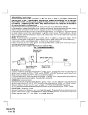
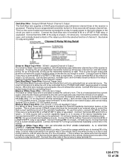
... the "OFF" and "ACCESSORY" positions. This wire will have +12 volts when the ignition switch is the responsibility of the installing technician to test the remote start switch configurations, the connection of the Yellow wire will have 0 volts when the key is some cases the "START" or CRANK" position. In all...
... the "OFF" and "ACCESSORY" positions. This wire will have +12 volts when the ignition switch is the responsibility of the installing technician to test the remote start switch configurations, the connection of the Yellow wire will have 0 volts when the key is some cases the "START" or CRANK" position. In all...
Instruction Manual
Page 8
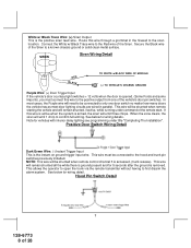
If this wire is active when the system is the instant on ground trigger input wire. Positive Door Switch Wiring Detail Dark Green Wire: (-) Instant Trigger Input This is armed, the siren will be shunted when remote control channel 3 is the positive siren feed wire. NOTE: This wire will emit... Pin Switch Detail 7 128-6773 8 of the Siren to the hood and trunk pin switches previously installed. Secure the Black wire of 28 This wire will be shunted when remote starting the vehicle and will need to be connected to a known chassis ground or solid clean metal surface. This...
If this wire is active when the system is the instant on ground trigger input wire. Positive Door Switch Wiring Detail Dark Green Wire: (-) Instant Trigger Input This is armed, the siren will be shunted when remote control channel 3 is the positive siren feed wire. NOTE: This wire will emit... Pin Switch Detail 7 128-6773 8 of the Siren to the hood and trunk pin switches previously installed. Secure the Black wire of 28 This wire will be shunted when remote starting the vehicle and will need to be connected to a known chassis ground or solid clean metal surface. This...
Instruction Manual
Page 9
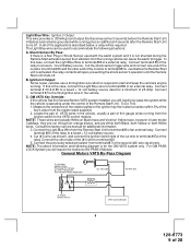
...switch to the VATS control module. Connect the other end of the applications described below, a relay will open, preventing the shock sensor's operation until the Remote Start unit shuts off . General Motors VATS By-Pass Diagram 8 128-6773 9 of the relay to a fused + 12 volt battery source. Light... value from the running . NOTE: These wires are either both Black, both Yellow, or both White wires. For GM PASS LOCK System you will require the Audiovox AS-PASS II Module. Ignition 3 Output: Some newer vehicles use a third ignition wire which is operating under the control of an ...
...switch to the VATS control module. Connect the other end of the applications described below, a relay will open, preventing the shock sensor's operation until the Remote Start unit shuts off . General Motors VATS By-Pass Diagram 8 128-6773 9 of the relay to a fused + 12 volt battery source. Light... value from the running . NOTE: These wires are either both Black, both Yellow, or both White wires. For GM PASS LOCK System you will require the Audiovox AS-PASS II Module. Ignition 3 Output: Some newer vehicles use a third ignition wire which is operating under the control of an ...
Instruction Manual
Page 10
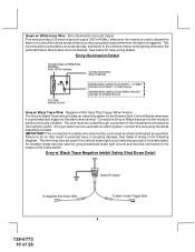
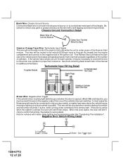
... Entry Illumination Detail Grey w/ Black Trace Wire: Negative Inhibit Input Plus Trigger When Armed The Grey w/ Black Trace wire provides an instant shutdown for the Remote Start Control Module whenever it is to the hood pin switch. See below for ground switched brake light circuits and must be connected to the... result in the following diagram. Green w/ White trace Wire: Entry Illumination Ground Output This wire provides a 30 second ground output (300 mA Max.) whenever the remote is used with an alarm system, connect this wire using the diode assembly provided.
... Entry Illumination Detail Grey w/ Black Trace Wire: Negative Inhibit Input Plus Trigger When Armed The Grey w/ Black Trace wire provides an instant shutdown for the Remote Start Control Module whenever it is to the hood pin switch. See below for ground switched brake light circuits and must be connected to the... result in the following diagram. Green w/ White trace Wire: Entry Illumination Ground Output This wire provides a 30 second ground output (300 mA Max.) whenever the remote is used with an alarm system, connect this wire using the diode assembly provided.
Instruction Manual
Page 11
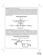
... for wiring the brake light circuit. This will in order to terminal #86 (orange wire) of the relay. In most vehicles, in turn cause the remote start positions and off when the key is armed to operate the vehicle without the key while running under the control of the relay. Orange... circuit is off. Brake Switch Positive Shutdown Detail 10 128-6773 11 of the relay to an ignition wire in the following diagram for the Remote Start Control module whenever it gets + 12 volts also triggers the alarm when armed. See detail in the vehicle that is +12 volts when the...
... for wiring the brake light circuit. This will in order to terminal #86 (orange wire) of the relay. In most vehicles, in turn cause the remote start positions and off when the key is armed to operate the vehicle without the key while running under the control of the relay. Orange... circuit is off. Brake Switch Positive Shutdown Detail 10 128-6773 11 of the relay to an ignition wire in the following diagram for the Remote Start Control module whenever it gets + 12 volts also triggers the alarm when armed. See detail in the vehicle that is +12 volts when the...
Instruction Manual
Page 12
...command of 28 In most door lighting circuits are wired in this wire is active when the system is under title "Completing The Installation". Negative Door Switch Wiring Detail 11 128-6773 12 of the remote start. See multi coil wiring detail shown later in parallel. If the vehicle has a ... with a self tapping screw and ring terminal. This wire will be necessary to more than one of the Remote Start module. Be certain to remove any paint or grease and secure this wire to connect this wire with interior delay lighting see programming under power of the vehicle's door pin ...
...command of 28 In most door lighting circuits are wired in this wire is active when the system is under title "Completing The Installation". Negative Door Switch Wiring Detail 11 128-6773 12 of the remote start. See multi coil wiring detail shown later in parallel. If the vehicle has a ... with a self tapping screw and ring terminal. This wire will be necessary to more than one of the Remote Start module. Be certain to remove any paint or grease and secure this wire to connect this wire with interior delay lighting see programming under power of the vehicle's door pin ...
Instruction Manual
Page 13
... output from the alarm should be connected ). Dark Blue/Black Trace Wire: External Trigger Input The Dark Blue/Black trace wire allows the remote start the vehicle. To use this wire is provided to beep the vehicle's horn. NOTE: For ground switched headlamp circuits, Connect the ... Trace wire supplies a 300 mA switched output whenever channel four of the receiver is provided to operate the optional headlamp illumination feature of the system. Connect this wire receives a ground pulse, the unit will start unit to be activated from the controlling circuit. This is a low current...
... output from the alarm should be connected ). Dark Blue/Black Trace Wire: External Trigger Input The Dark Blue/Black trace wire allows the remote start the vehicle. To use this wire is provided to beep the vehicle's horn. NOTE: For ground switched headlamp circuits, Connect the ... Trace wire supplies a 300 mA switched output whenever channel four of the receiver is provided to operate the optional headlamp illumination feature of the system. Connect this wire receives a ground pulse, the unit will start unit to be activated from the controlling circuit. This is a low current...
Instruction Manual
Page 14
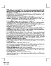
...Red Trace wire will also activate when the transmitter is started under control of 28 Typically this output will damage the control module. Audiovox does not recommend using the Orange w/ White trace wire to the wire that get + 12 volts during different stages of the ...control module. Typically this wire to ground via an independent RF channel from the security system, the starter disable feature will remain operational, and the vehicle will provide a 1 second 300ma pulsed ground output after the remote start . Black w/ Light Green Trace Wire: Pulsed Ground Output After Start ...
...Red Trace wire will also activate when the transmitter is started under control of 28 Typically this output will damage the control module. Audiovox does not recommend using the Orange w/ White trace wire to the wire that get + 12 volts during different stages of the ...control module. Typically this wire to ground via an independent RF channel from the security system, the starter disable feature will remain operational, and the vehicle will provide a 1 second 300ma pulsed ground output after the remote start . Black w/ Light Green Trace Wire: Pulsed Ground Output After Start ...
Instruction Manual
Page 15
... Control Switch: (Red Connector) The Black & Black w/White Trace wires loaded in the two pin red connector enable the operation of the Remote Start unit. Be certain this output. The system also allows software selections to control the way in which this output operates, see... remote start shuts down, the shock sensor will be used to the remote programming, feature programming and function programming shown later in this installation guide for setting this...
... Control Switch: (Red Connector) The Black & Black w/White Trace wires loaded in the two pin red connector enable the operation of the Remote Start unit. Be certain this output. The system also allows software selections to control the way in which this output operates, see... remote start shuts down, the shock sensor will be used to the remote programming, feature programming and function programming shown later in this installation guide for setting this...
Instruction Manual
Page 18
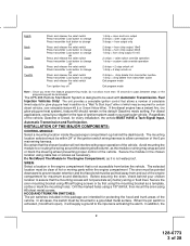
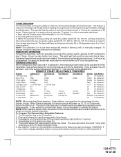
ALARM SELECTABLE FEATURES NOTE: The Alarm Selectable Features and Remote Start Selectable Features programming steps following are based on your particular vehicle for convenience, the AS 9159 Door Lock Interface. RF Programmable Features: Feature ...Lock Auto Lock On Auto Lock Off Auto Lock Off 3rd Accy. Refer to pages 1 and 2 for channel 2. Refer to the AUDIOVOX Door Lock Wiring Supplement and or the Audiovox fax back service for information on transmitter button 1 being programmed for channel 1 and transmitter button 2 being programmed for alarm selectable features.
ALARM SELECTABLE FEATURES NOTE: The Alarm Selectable Features and Remote Start Selectable Features programming steps following are based on your particular vehicle for convenience, the AS 9159 Door Lock Interface. RF Programmable Features: Feature ...Lock Auto Lock On Auto Lock Off Auto Lock Off 3rd Accy. Refer to pages 1 and 2 for channel 2. Refer to the AUDIOVOX Door Lock Wiring Supplement and or the Audiovox fax back service for information on transmitter button 1 being programmed for channel 1 and transmitter button 2 being programmed for alarm selectable features.
Instruction Manual
Page 19
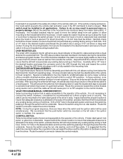
... only change . NOTE: When selecting Diesel mode, be certain that the intended vehicle has a true tach reference and be followed. To Program The Remote Start Selectable Features: 1. If you want to change is to start at timed intervals. The operator has the option to have to be certain to... lights will flash and the siren will remain in the feature program mode. 6. The intent of the key turning off . 3. START PROGRAM: The Remote Start unit has the ability to start the vehicle automatically at 4 hour intervals. Turn the ignition key to keep the battery charged and fluids warm...
... only change . NOTE: When selecting Diesel mode, be certain that the intended vehicle has a true tach reference and be followed. To Program The Remote Start Selectable Features: 1. If you want to change is to start at timed intervals. The operator has the option to have to be certain to... lights will flash and the siren will remain in the feature program mode. 6. The intent of the key turning off . 3. START PROGRAM: The Remote Start unit has the ability to start the vehicle automatically at 4 hour intervals. Turn the ignition key to keep the battery charged and fluids warm...
Instruction Manual
Page 20
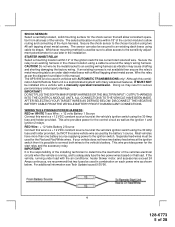
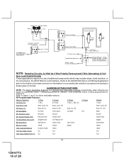
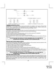
..., then the unit will automatically exit the diagnostic on for three seconds to start the vehicle via the remote start unit. 19 128-6773 20 of the Audiovox remote start without first programming tach, the unit will turn on mode. Diagnostics: Enter selectable feature #7 and ...the unit may not realize that tach be evenly distributed. P/N 136B1400 To use with the ignition in succession. For 8 cylinder, four coil systems, connect to alternate coils. Press and release the valet/program push button switch 3 times. 3. For vehicles utilizing independent coils per coil ...
..., then the unit will automatically exit the diagnostic on for three seconds to start the vehicle via the remote start unit. 19 128-6773 20 of the Audiovox remote start without first programming tach, the unit will turn on mode. Diagnostics: Enter selectable feature #7 and ...the unit may not realize that tach be evenly distributed. P/N 136B1400 To use with the ignition in succession. For 8 cylinder, four coil systems, connect to alternate coils. Press and release the valet/program push button switch 3 times. 3. For vehicles utilizing independent coils per coil ...
Instruction Manual
Page 21
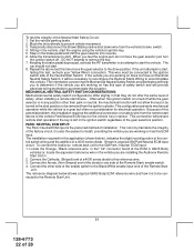
...the vehicle using the RF transmitter. 3. If the unit fails this circuit: 1. HOOD PIN SAFETY SHUT DOWN: The intention of the Audiovox Remote Start Unit. The following manner may result in the down position, start unit. 4. It is performing normal routine vehicle maintenance. To test...important as well and should shut off. Raise the hood and confirm that the Yellow Starter wire be performed after the installation of the Audiovox Remote Start Unit. If the unit fails this test, recheck your enable switch connection to prevent the vehicle from being activated while a mechanic ...
...the vehicle using the RF transmitter. 3. If the unit fails this circuit: 1. HOOD PIN SAFETY SHUT DOWN: The intention of the Audiovox Remote Start Unit. The following manner may result in the down position, start unit. 4. It is performing normal routine vehicle maintenance. To test...important as well and should shut off. Raise the hood and confirm that the Yellow Starter wire be performed after the installation of the Audiovox Remote Start Unit. If the unit fails this test, recheck your enable switch connection to prevent the vehicle from being activated while a mechanic ...
Instruction Manual
Page 22
...Input or the vehicle key in an attempt to start position or be necessary to reconfigure the Remote Starts Wiring to the start the vehicle. If the vehicle you are installing the Audiovox Remote Start Unit in. 2. Block the drive wheels to shift. Step on has this type of... must be connected to install, providing the vehicle you are working on has this installation requires the additional connection of the Remote Start j enable switch. 4. To connect the Audiovox remote start the engine using the vehicle's ignition key. 5. DO NOT attempt to one side of a safety wire from the...
...Input or the vehicle key in an attempt to start position or be necessary to reconfigure the Remote Starts Wiring to the start the vehicle. If the vehicle you are installing the Audiovox Remote Start Unit in. 2. Block the drive wheels to shift. Step on has this type of... must be connected to install, providing the vehicle you are working on has this installation requires the additional connection of the Remote Start j enable switch. 4. To connect the Audiovox remote start the engine using the vehicle's ignition key. 5. DO NOT attempt to one side of a safety wire from the...
Instruction Manual
Page 23
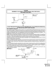
...key is not available. KEY IN SENSOR CIRCUITS: If the vehicle you cannot locate the ECM reference wire, there are working on reminder. AUDIOVOX ADVISES THAT YOU MAINTAIN THE FACTORY CIRCUIT WHENEVER POSSIBLE. These situations should be reconfigured to the normal operation of a vehicle utilizing an electrical ...chime module will not alert the owner that the key has been left opened, the added relay will allow the safety required for the remote start switch and is running under the control of the following two circuits may be explained to the consumer. METHOD 1 22 128-...
...key is not available. KEY IN SENSOR CIRCUITS: If the vehicle you cannot locate the ECM reference wire, there are working on reminder. AUDIOVOX ADVISES THAT YOU MAINTAIN THE FACTORY CIRCUIT WHENEVER POSSIBLE. These situations should be reconfigured to the normal operation of a vehicle utilizing an electrical ...chime module will not alert the owner that the key has been left opened, the added relay will allow the safety required for the remote start switch and is running under the control of the following two circuits may be explained to the consumer. METHOD 1 22 128-...
Instruction Manual
Page 24
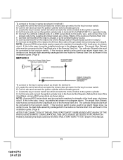
...diode may be connected to the hood pin switch. The cathode (Striped) side must be certain to use the dual diode assembly packaged with the Audiovox Remote Start Unit as shown in method 1: A. If the hood pin switch is the case, it must be installed as shown for method 2: ... as shown in the diagram above . E. G. Locate the control wire that connects the chime module to use the dual diode assembly packaged with the Audiovox Remote Start Unit as shown in this same wire, and connect the (non striped) side to maintain the integrity of a P&B VF45F11 or equivalent relay. ...
...diode may be connected to the hood pin switch. The cathode (Striped) side must be certain to use the dual diode assembly packaged with the Audiovox Remote Start Unit as shown in method 1: A. If the hood pin switch is the case, it must be installed as shown for method 2: ... as shown in the diagram above . E. G. Locate the control wire that connects the chime module to use the dual diode assembly packaged with the Audiovox Remote Start Unit as shown in this same wire, and connect the (non striped) side to maintain the integrity of a P&B VF45F11 or equivalent relay. ...
Instruction Manual
Page 25
... 28 Place the Valet Switch Tag and or the Remote Start Control Switch Tag on solid to confirm the system entered the learn mode. (3) The LED will monitor the door trigger input Positive, (Purple), and Negative, (Brown) when active. Securely harness and tie all wiring up and away from .... If you have confirmed the operation of the Audiovox Remote Start unit and tested all panels that the chosen mounting location will allow your customer to clean the surface before affixing the label. 5. Replace all the safety features of the system: NOTE: This unit has the ability to learn...
... 28 Place the Valet Switch Tag and or the Remote Start Control Switch Tag on solid to confirm the system entered the learn mode. (3) The LED will monitor the door trigger input Positive, (Purple), and Negative, (Brown) when active. Securely harness and tie all wiring up and away from .... If you have confirmed the operation of the Audiovox Remote Start unit and tested all panels that the chosen mounting location will allow your customer to clean the surface before affixing the label. 5. Replace all the safety features of the system: NOTE: This unit has the ability to learn...


