
User Guide
Page 14
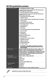
Z97-WS specifications summary Internal I/O connectors BIOS features Manageability Support DVD contents Operating system support Form factor 4 x SATA 6Gb/s Connectors (4 x gray) 1 x 4-pin CPU Fan connector for both 3-pin (DC mode) and 4-pin (PWM mode) CPU coolers control* 1 x 4-pin CPU Optional Fan connector (CPU_OPT) 4 x 4-pin Chassis Fan connectors for 3-pin (DC mode) and 4-pin (PWM mode) coolers control 1 x Front panel audio...
Z97-WS specifications summary Internal I/O connectors BIOS features Manageability Support DVD contents Operating system support Form factor 4 x SATA 6Gb/s Connectors (4 x gray) 1 x 4-pin CPU Fan connector for both 3-pin (DC mode) and 4-pin (PWM mode) CPU coolers control* 1 x 4-pin CPU Optional Fan connector (CPU_OPT) 4 x 4-pin Chassis Fan connectors for 3-pin (DC mode) and 4-pin (PWM mode) coolers control 1 x Front panel audio...
User Guide
Page 21
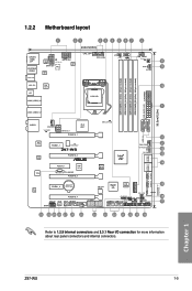
...) DDR3 DIMM_B1 (64bit, 240-pin module) DDR3 DIMM_B2 (64bit, 240-pin module) 30.5cm(12.0in) PWR_SUPPLY LED USB3_E12 AUDIO CHA_FAN1 VGA_LED EATX12V_1 PCIEX16_1 PLX 8747 DIAG_CPU LED USB3_34 WGI 210AT WGI 218LM TPU PCIEX1_1 ICS 9DB433AGLF Z97-WS PCIEX16_2 PCIEX4_1 ASM 1187e TB_HEADER PCIEX16_3 Intel® Z97 CHA_FAN3 DR.Power LED DR_POWER SATA6G_1 SATA6G_2 BIOS...
...) DDR3 DIMM_B1 (64bit, 240-pin module) DDR3 DIMM_B2 (64bit, 240-pin module) 30.5cm(12.0in) PWR_SUPPLY LED USB3_E12 AUDIO CHA_FAN1 VGA_LED EATX12V_1 PCIEX16_1 PLX 8747 DIAG_CPU LED USB3_34 WGI 210AT WGI 218LM TPU PCIEX1_1 ICS 9DB433AGLF Z97-WS PCIEX16_2 PCIEX4_1 ASM 1187e TB_HEADER PCIEX16_3 Intel® Z97 CHA_FAN3 DR.Power LED DR_POWER SATA6G_1 SATA6G_2 BIOS...
User Guide
Page 22
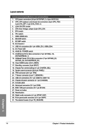
... 10. CPU, CPU optional, and chassis fan connectors (4-pin CPU_FAN, 4-pin CPU_OPT, 4-pin CHA_FAN1-4 ) 3. TPU switch 7. Dr. Power LED 13. ASUS Dr. POWER switch 14. System panel connector (20-8 pin PANEL) 20. Chassis Intrusion connector (4-1 pin CHASSIS) 24. Front panel audio connector (10-1 pin AAFP) 31. Intel® Serial ATA 6 Gb/s connectors (7-pin SATA6G_1/6, SATAEXPRESS_1) 15. ASMedia® Serial ATA...
... 10. CPU, CPU optional, and chassis fan connectors (4-pin CPU_FAN, 4-pin CPU_OPT, 4-pin CHA_FAN1-4 ) 3. TPU switch 7. Dr. Power LED 13. ASUS Dr. POWER switch 14. System panel connector (20-8 pin PANEL) 20. Chassis Intrusion connector (4-1 pin CHASSIS) 24. Front panel audio connector (10-1 pin AAFP) 31. Intel® Serial ATA 6 Gb/s connectors (7-pin SATA6G_1/6, SATAEXPRESS_1) 15. ASMedia® Serial ATA...

User Guide
Page 34
...problem is solved. To go back to its default CPU voltage setting, insert the jumper to pins 2-3. DRAM LED Z97-WS CPU_LED VGA_LED Z97-WS CPU/DRAM/VGA LED Chapter 1 1-18 Chapter 1: Product introduction Z97-WS Z97-WS CPU_OV setting CPU_OV 12 23 Disable Enable (default setting) 1.2.8 Onboard LEDs 1. POST State ...of the installed CPU. CPU Over Voltage jumper (3-pin CPU_OV) The CPU Over Voltage jumper allows you to set a higher CPU voltage for a flexible overclocking system, depending on the type of these key components during POST (Power-On-Self Test): CPU, memory modules, VGA ...
...problem is solved. To go back to its default CPU voltage setting, insert the jumper to pins 2-3. DRAM LED Z97-WS CPU_LED VGA_LED Z97-WS CPU/DRAM/VGA LED Chapter 1 1-18 Chapter 1: Product introduction Z97-WS Z97-WS CPU_OV setting CPU_OV 12 23 Disable Enable (default setting) 1.2.8 Onboard LEDs 1. POST State ...of the installed CPU. CPU Over Voltage jumper (3-pin CPU_OV) The CPU Over Voltage jumper allows you to set a higher CPU voltage for a flexible overclocking system, depending on the type of these key components during POST (Power-On-Self Test): CPU, memory modules, VGA ...

User Guide
Page 46
...a USB 3.0 module for USB-chargeable devices, optimized power efficiency, and backward compatibility with USB 2.0. USB 3.0 connectors (20-1 pin USB3_E12, USB3_E34) These connectors allow you can enjoy...Z97-WS USB3_E12 Vbus IntA_P2_SSRXIntA_P2_SSRX+ GND IntA_P2_SSTXIntA_P2_SSTX+ GND IntA_P2_DIntA_P2_D+ PIN 1 Vbus IntA_P1_SSRXIntA_P1_SSRX+ GND IntA_P1_SSTXIntA_P1_SSTX+ GND IntA_P1_DIntA_P1_D+ ID USB3_E34 Vbus IntA_P2_SSRXIntA_P2_SSRX+ GND IntA_P2_SSTXIntA_P2_SSTX+ GND IntA_P2_DIntA_P2_D+ PIN 1 Vbus IntA_P1_SSRXIntA_P1_SSRX+ GND IntA_P1_SSTXIntA_P1_SSTX+ GND IntA_P1_DIntA_P1_D+ ID Z97-WS...
...a USB 3.0 module for USB-chargeable devices, optimized power efficiency, and backward compatibility with USB 2.0. USB 3.0 connectors (20-1 pin USB3_E12, USB3_E34) These connectors allow you can enjoy...Z97-WS USB3_E12 Vbus IntA_P2_SSRXIntA_P2_SSRX+ GND IntA_P2_SSTXIntA_P2_SSTX+ GND IntA_P2_DIntA_P2_D+ PIN 1 Vbus IntA_P1_SSRXIntA_P1_SSRX+ GND IntA_P1_SSTXIntA_P1_SSTX+ GND IntA_P1_DIntA_P1_D+ ID USB3_E34 Vbus IntA_P2_SSRXIntA_P2_SSRX+ GND IntA_P2_SSTXIntA_P2_SSTX+ GND IntA_P2_DIntA_P2_D+ PIN 1 Vbus IntA_P1_SSRXIntA_P1_SSRX+ GND IntA_P1_SSTXIntA_P1_SSTX+ GND IntA_P1_DIntA_P1_D+ ID Z97-WS...
User Guide
Page 48
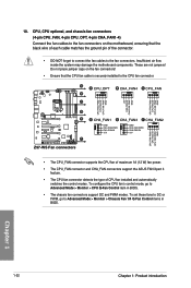
...pin of CPU fan installed and automatically switches the control modes. A A CPU_OPT B CHA_FAN4 C CPU_FAN B C CPU FAN PWM CPU FAN IN CPU FAN PWR GND +5V CHA FAN IN CHA FAN PWR GND CPU FAN PWM CPU FAN IN CPU FAN PWR GND D E Z97-WS F Z97-WS... Fan connectors D CHA_FAN1 E CHA_FAN3 F CHA_FAN2 GND CHA FAN PWR CHA FAN IN +5V GND CHA FAN PWR CHA FAN IN +5V CPU FAN PWM CPU FAN IN CPU FAN PWR GND • The CPU_FAN connector supports the CPU fan of maximum 1A (12 W) fan power.... • The CPU_FAN connector and CHA_FAN connectors support the ASUS FAN Xpert 3 feature...
...pin of CPU fan installed and automatically switches the control modes. A A CPU_OPT B CHA_FAN4 C CPU_FAN B C CPU FAN PWM CPU FAN IN CPU FAN PWR GND +5V CHA FAN IN CHA FAN PWR GND CPU FAN PWM CPU FAN IN CPU FAN PWR GND D E Z97-WS F Z97-WS... Fan connectors D CHA_FAN1 E CHA_FAN3 F CHA_FAN2 GND CHA FAN PWR CHA FAN IN +5V GND CHA FAN PWR CHA FAN IN +5V CPU FAN PWM CPU FAN IN CPU FAN PWR GND • The CPU_FAN connector supports the CPU fan of maximum 1A (12 W) fan power.... • The CPU_FAN connector and CHA_FAN connectors support the ASUS FAN Xpert 3 feature...
User Guide
Page 49
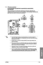
... PSON# GND -12 Volts +3 Volts PIN 1 • For a fully configured system, we recommend that you use a power supply unit (PSU) that you want to connect the 4-pin/8-pin EATX12 V power plug. Chapter 1 Z97-WS 1-33 The power supply plugs are for details. The system...power supply plugs. Find the proper orientation and push down firmly until the connectors completely fit. ATX power connectors (24-pin EATXPWR; 8-pin EATX12V1, 8-pin EATX12V, 8-pin EATX12V1, 6-pin EATX12V) These connectors are designed to the Recommended Power Supply Wattage Calculator at http://support.asus...
... PSON# GND -12 Volts +3 Volts PIN 1 • For a fully configured system, we recommend that you use a power supply unit (PSU) that you want to connect the 4-pin/8-pin EATX12 V power plug. Chapter 1 Z97-WS 1-33 The power supply plugs are for details. The system...power supply plugs. Find the proper orientation and push down firmly until the connectors completely fit. ATX power connectors (24-pin EATXPWR; 8-pin EATX12V1, 8-pin EATX12V, 8-pin EATX12V1, 6-pin EATX12V) These connectors are designed to the Recommended Power Supply Wattage Calculator at http://support.asus...
User Guide
Page 50
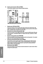
.... The HDD LED lights up when you to the HDD. • System warning speaker (4-pin SPEAKER) This 4-pin connector is for the system power LED. PLED+ PLED+5V Ground Ground Speaker Z97-WS PLED SPEAKER PANEL PIN 1 HDD_LED+ HDD_LED- The system power LED lights up or flashes when data is read from or written to hear system...
.... The HDD LED lights up when you to the HDD. • System warning speaker (4-pin SPEAKER) This 4-pin connector is for the system power LED. PLED+ PLED+5V Ground Ground Speaker Z97-WS PLED SPEAKER PANEL PIN 1 HDD_LED+ HDD_LED- The system power LED lights up or flashes when data is read from or written to hear system...
User Guide
Page 51
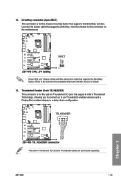
... button cable that supports Intel's Thunderbolt Technology, allowing you to connect up to this connector on the motherboard. Z97-WS 1-35 GND Plafform Sequence Control Plafform Sequence Control Plug_Event Power Chapter 1 13. Z97-WS DRCT DRCT GND PIN 1 Z97-WS CPU_OV setting Ensure that your chassis comes with the chassis for the add-on Thunderbolt I /O card that supports...
... button cable that supports Intel's Thunderbolt Technology, allowing you to connect up to this connector on the motherboard. Z97-WS 1-35 GND Plafform Sequence Control Plafform Sequence Control Plug_Event Power Chapter 1 13. Z97-WS DRCT DRCT GND PIN 1 Z97-WS CPU_OV setting Ensure that your chassis comes with the chassis for the add-on Thunderbolt I /O card that supports...
User Guide
Page 123
... options: [1 sec] - [10 sec] [Until Press ESC] Bootup NumLock State [On] This item allows you press the Reset button. Connect the 2-pin connector of the NumLock. Post Delay Time [3 sec] This item allows you set the Boot Logo Display to [Auto] and [Full Screen]. The following ...occurs. You can only execute the POST delay time during POST. Configuration options: [Disabled] [Enabled] Chapter 3 Z97-WS 3-51 Post Report [5 sec] This item allows you set under normal boot. The system will only power on or off when you press the DirectKey button. [Enabled] Allows the system to...
... options: [1 sec] - [10 sec] [Until Press ESC] Bootup NumLock State [On] This item allows you press the Reset button. Connect the 2-pin connector of the NumLock. Post Delay Time [3 sec] This item allows you set the Boot Logo Display to [Auto] and [Full Screen]. The following ...occurs. You can only execute the POST delay time during POST. Configuration options: [Disabled] [Enabled] Chapter 3 Z97-WS 3-51 Post Report [5 sec] This item allows you set under normal boot. The system will only power on or off when you press the DirectKey button. [Enabled] Allows the system to...
