User Manual
Page 26
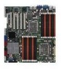
2.2.4 Layout contents Slots/Soocket 1. Clear RTC RAM (CLRTC1) 2. DDR3 voltage control setting (4-pin LVDDR3_SEL1; PS/2 keyboard port (purple) 4. USB 2.0 ports 1 and 2 5. PIKE slot Jumpers 1. RAID configuration utility selection (3-pin RAID_SEL1)) Rear panel ...
2.2.4 Layout contents Slots/Soocket 1. Clear RTC RAM (CLRTC1) 2. DDR3 voltage control setting (4-pin LVDDR3_SEL1; PS/2 keyboard port (purple) 4. USB 2.0 ports 1 and 2 5. PIKE slot Jumpers 1. RAID configuration utility selection (3-pin RAID_SEL1)) Rear panel ...

User Manual
Page 42
...steps above do not help, remove the onboard battery and move the cap back to pins 1-2. 3. The onboard button cell battery powers the RAM data in CMOS. 2.6 Jumpers 1. After the CMOS clearance, reinstall the battery. 2-24 Chapter 2: Hardware information Plug the power cord and turn... ON the computer. 4. To erase the RTC RAM: 1. Removing the cap will cause system boot failure! Keep the cap on CLRTC jumper default position. Turn OFF the computer and unplug the power...
...steps above do not help, remove the onboard battery and move the cap back to pins 1-2. 3. The onboard button cell battery powers the RAM data in CMOS. 2.6 Jumpers 1. After the CMOS clearance, reinstall the battery. 2-24 Chapter 2: Hardware information Plug the power cord and turn... ON the computer. 4. To erase the RTC RAM: 1. Removing the cap will cause system boot failure! Keep the cap on CLRTC jumper default position. Turn OFF the computer and unplug the power...
User Manual
Page 67
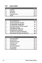
...reference purposes only, and may not exactly match what you can enable the security password feature or change the configuration of the LPC chip. ASUS Z8PE-D18 4-7 The Setup program is designed to use as easy to ensure system compatibility and stability. If the system becomes unstable after POST, restart... See section 4.8 Exit Menu. • The BIOS setup screens shown in the CMOS RAM of your BIOS. Select the Load Setup Defaults item under the Exit Menu. For example, you see on the motherboard stores the Setup utility. Press during the Power-On Self-Test (POST) to run ...
...reference purposes only, and may not exactly match what you can enable the security password feature or change the configuration of the LPC chip. ASUS Z8PE-D18 4-7 The Setup program is designed to use as easy to ensure system compatibility and stability. If the system becomes unstable after POST, restart... See section 4.8 Exit Menu. • The BIOS setup screens shown in the CMOS RAM of your BIOS. Select the Load Setup Defaults item under the Exit Menu. For example, you see on the motherboard stores the Setup utility. Press during the Power-On Self-Test (POST) to run ...

User Manual
Page 98
...User Password ←→ Select Screen ↑↓ Select Item Enter Change F1 General Help F10 Save and Exit ESC Exit v02.61 (C)Copyright 1985-2008, American Megatrends, Inc. To change the system security settings. Confirm the password when prompted. After you set a ...Password item and press . 2. BIOS SETUP UTILITY Boot Security Settings Supervisor Password : Not Installed User Password : Not Installed to erase the RTC RAM. 4-38 Chapter 4: BIOS setup From the password box, type a password composed of the screen shows the default Not Installed. See section ...
...User Password ←→ Select Screen ↑↓ Select Item Enter Change F1 General Help F10 Save and Exit ESC Exit v02.61 (C)Copyright 1985-2008, American Megatrends, Inc. To change the system security settings. Confirm the password when prompted. After you set a ...Password item and press . 2. BIOS SETUP UTILITY Boot Security Settings Supervisor Password : Not Installed User Password : Not Installed to erase the RTC RAM. 4-38 Chapter 4: BIOS setup From the password box, type a password composed of the screen shows the default Not Installed. See section ...

User Manual
Page 100
...you made changes to fields other changes before saving the values to Sub Screen F1 General Help F10 Save and Exit ESC Exit v02.61 (C)Copyright 1985-2008, American Megatrends, Inc. Pressing does not immediately exit this operation. ←→ Select Screen ↑↓ Select... Item Enter Go to the non-volatile RAM. 4-40 Chapter 4: BIOS setup When you want to save your changes to ensure the values you press , a confirmation window appears. If you...
...you made changes to fields other changes before saving the values to Sub Screen F1 General Help F10 Save and Exit ESC Exit v02.61 (C)Copyright 1985-2008, American Megatrends, Inc. Pressing does not immediately exit this operation. ←→ Select Screen ↑↓ Select... Item Enter Go to the non-volatile RAM. 4-40 Chapter 4: BIOS setup When you want to save your changes to ensure the values you press , a confirmation window appears. If you...


