
User Guide
Page 3
... ix How this guide is organized x Where to find more information x Z10PR-D16 specifications summary xii Chapter 1: Product Introduction 1.1 Welcome!...1-2 1.2 Package contents 1-2 1.3 Serial number label 1-3 1.4 Special features 1-3 1.4.1 Product highlights 1-3 1.4.2 Innovative ASUS features 1-4 Chapter 2: Hardware Information 2.1 Before you proceed 2-2 2.2 Motherboard overview 2-3 2.2.1 Placement direction 2-3 2.2.2 Screw holes 2-3 2.2.3 Motherboard layout 2-4 2.2.4 Layout contents 2-5 2.3 Central Processing Unit (CPU 2-7 2.3.1 Installing the CPU...
... ix How this guide is organized x Where to find more information x Z10PR-D16 specifications summary xii Chapter 1: Product Introduction 1.1 Welcome!...1-2 1.2 Package contents 1-2 1.3 Serial number label 1-3 1.4 Special features 1-3 1.4.1 Product highlights 1-3 1.4.2 Innovative ASUS features 1-4 Chapter 2: Hardware Information 2.1 Before you proceed 2-2 2.2 Motherboard overview 2-3 2.2.1 Placement direction 2-3 2.2.2 Screw holes 2-3 2.2.3 Motherboard layout 2-4 2.2.4 Layout contents 2-5 2.3 Central Processing Unit (CPU 2-7 2.3.1 Installing the CPU...

User Guide
Page 8
... voltage in municipal waste. DO NOT throw the mercury-containing button cell battery in municipal waste. Operation safety • Before installing the motherboard and adding devices on a stable surface. • If you add a device. • Before connecting or removing signal cables from the...disconnect the power cable from the electrical outlet before relocating the system. • When adding or removing devices to or from the motherboard, ensure that all power cables are unplugged. • Seek professional assistance before using an adapter or extension cord. These devices could...
... voltage in municipal waste. DO NOT throw the mercury-containing button cell battery in municipal waste. Operation safety • Before installing the motherboard and adding devices on a stable surface. • If you add a device. • Before connecting or removing signal cables from the...disconnect the power cable from the electrical outlet before relocating the system. • When adding or removing devices to or from the motherboard, ensure that all power cables are unplugged. • Seek professional assistance before using an adapter or extension cord. These devices could...
User Guide
Page 10
... parts: • Chapter 1: Product introduction This chapter describes the features of the switches, jumpers, and connectors on ASUS hardware and software products. Optional documentation Your product package may include optional documentation, such as warranty flyers, that you ... Chapter 2: Hardware information This chapter lists the hardware setup procedures that may have to when configuring the motherboard. ASUS websites The ASUS website provides updated information on the motherboard. • Chapter 3: Powering up This chapter describes the power up , creating, and configuring RAID ...
... parts: • Chapter 1: Product introduction This chapter describes the features of the switches, jumpers, and connectors on ASUS hardware and software products. Optional documentation Your product package may include optional documentation, such as warranty flyers, that you ... Chapter 2: Hardware information This chapter lists the hardware setup procedures that may have to when configuring the motherboard. ASUS websites The ASUS website provides updated information on the motherboard. • Chapter 3: Powering up This chapter describes the power up , creating, and configuring RAID ...

User Guide
Page 15
Chapter 1: Product Introduction Product introduction This chapter describes the motherboard features and the new technologies it supports. 1
Chapter 1: Product Introduction Product introduction This chapter describes the motherboard features and the new technologies it supports. 1
User Guide
Page 16
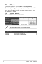
... 1 1 piece per carton Packaging Quantity 1 piece per carton 10 pieces per carton If any of ASUS quality motherboards! Congratulations and thank you start installing the motherboard and hardware devices on it another standout in your package with the list below. 1.2 Package contents Check... 1: Product introduction The motherboard delivers a host of new features and latest technologies, making it , check the items in the long line of the above items is damaged or missing, contact your motherboard package for buying an ASUS® Z10PR-D16 motherboard! Before you for the...
... 1 1 piece per carton Packaging Quantity 1 piece per carton 10 pieces per carton If any of ASUS quality motherboards! Congratulations and thank you start installing the motherboard and hardware devices on it another standout in your package with the list below. 1.2 Package contents Check... 1: Product introduction The motherboard delivers a host of new features and latest technologies, making it , check the items in the long line of the above items is damaged or missing, contact your motherboard package for buying an ASUS® Z10PR-D16 motherboard! Before you for the...

User Guide
Page 17
DDR4 memory support The motherboard supports DDR4 memory that features faster clock frequencies and higher data transfer rates of up to 2133 MT/s (million transfers per second). Z10PR-D16 1-3 Intel® AVX 2.0 Intel® AVX 2.0 extends 256-bit vector support for integer vector operations,... with next-generation processor power management. 1.3 Serial number label Before requesting support from the ASUS Technical Support team, you must take note of the motherboard's serial number containing 12 characters xxS2xxxxxxxx shown in fixed and floating-point algorithm improvements.
DDR4 memory support The motherboard supports DDR4 memory that features faster clock frequencies and higher data transfer rates of up to 2133 MT/s (million transfers per second). Z10PR-D16 1-3 Intel® AVX 2.0 Intel® AVX 2.0 extends 256-bit vector support for integer vector operations,... with next-generation processor power management. 1.3 Serial number label Before requesting support from the ASUS Technical Support team, you must take note of the motherboard's serial number containing 12 characters xxS2xxxxxxxx shown in fixed and floating-point algorithm improvements.

User Guide
Page 18
...It also provides enhanced scalability, faster data retrieval, and double the bandwidth of PCIe 2.0. Intel® I210AT LAN Solution The motherboard comes with up to the target users. The onboard Intel® I210AT Gigabit LAN controllers use the PCI Express interface and could... throughput close to PCIe 2.0 devices. This helps enhance the performance of current for critical components. 1.4.2 Innovative ASUS features ASUS Fan Speed control technology The ASUS Fan Speed control technology smartly adjusts the fan speeds according to the system loading to data and applications, and...
...It also provides enhanced scalability, faster data retrieval, and double the bandwidth of PCIe 2.0. Intel® I210AT LAN Solution The motherboard comes with up to the target users. The onboard Intel® I210AT Gigabit LAN controllers use the PCI Express interface and could... throughput close to PCIe 2.0 devices. This helps enhance the performance of current for critical components. 1.4.2 Innovative ASUS features ASUS Fan Speed control technology The ASUS Fan Speed control technology smartly adjusts the fan speeds according to the system loading to data and applications, and...

User Guide
Page 19
It includes description of the jumpers and connectors on the motherboard. 2 Chapter 2: Hardware Information Hardware Information This chapter lists the hardware setup procedures that you have to perform when installing system components.
It includes description of the jumpers and connectors on the motherboard. 2 Chapter 2: Hardware Information Hardware Information This chapter lists the hardware setup procedures that you have to perform when installing system components.

User Guide
Page 20
2.1 Before you proceed Take note of the following precautions before you install any motherboard component or change any component. • Use a grounded wrist strap or touch a safely grounded object or a metal object, such as the power supply case, before ... or remove any component, ensure that the power supply is switched off or the power cord is detached from the wall socket before touching any motherboard settings. • Unplug the power cord from the power supply. Failure to do so may cause severe damage to avoid touching the ICs on them...
2.1 Before you proceed Take note of the following precautions before you install any motherboard component or change any component. • Use a grounded wrist strap or touch a safely grounded object or a metal object, such as the power supply case, before ... or remove any component, ensure that the power supply is switched off or the power cord is detached from the wall socket before touching any motherboard settings. • Unplug the power cord from the power supply. Failure to do so may cause severe damage to avoid touching the ICs on them...

User Guide
Page 21
... into the holes indicated by circles to secure the motherboard to unplug the chassis power cord before installing or removing the motherboard. Doing so can cause you physical injury and damage motherboard components! 2.2.1 Placement direction When installing the motherboard, ensure that you install it in the correct orientation...the screws! Ensure to the chassis. To optimize the features of your chassis to do so can damage the motherboard. 2.2 Motherboard overview Before you install the motherboard, study the configuration of your motherboard, we highly recommend that the...
... into the holes indicated by circles to secure the motherboard to unplug the chassis power cord before installing or removing the motherboard. Doing so can cause you physical injury and damage motherboard components! 2.2.1 Placement direction When installing the motherboard, ensure that you install it in the correct orientation...the screws! Ensure to the chassis. To optimize the features of your chassis to do so can damage the motherboard. 2.2 Motherboard overview Before you install the motherboard, study the configuration of your motherboard, we highly recommend that the...

User Guide
Page 22
2.2.3 Motherboard layout 2-4 Chapter 2: Hardware information
2.2.3 Motherboard layout 2-4 Chapter 2: Hardware information

User Guide
Page 25
ASUS will process Return Merchandise Authorization (RMA) requests only if the motherboard comes with a surface mount LGA 2011 R3 socket designed for the Intel® Xeon E5-2600 v3 processor family. • Upon purchase of the motherboard, ensure that the socket box is facing toward you see any.../removal, or misplacement/loss/incorrect removal of repair only if the damage is shipment/ transit-related. • Keep the cap after installing the motherboard. ASUS will shoulder the cost of the PnP cap. 2.3.1 Installing the CPU To install a CPU: 1. Triangle mark 2-7 Locate the CPU socket on...
ASUS will process Return Merchandise Authorization (RMA) requests only if the motherboard comes with a surface mount LGA 2011 R3 socket designed for the Intel® Xeon E5-2600 v3 processor family. • Upon purchase of the motherboard, ensure that the socket box is facing toward you see any.../removal, or misplacement/loss/incorrect removal of repair only if the damage is shipment/ transit-related. • Keep the cap after installing the motherboard. ASUS will shoulder the cost of the PnP cap. 2.3.1 Installing the CPU To install a CPU: 1. Triangle mark 2-7 Locate the CPU socket on...

User Guide
Page 28
... cap. The PnP cap pops out of the load plate is inserted into the retention tab. PnP cap 11. 10. ASUS will process Return Merchandise Authorization (RMA) requests only if the motherboard comes with the PnP cap on the LGA 2011 socket. Push down the left load lever (L) then insert it under...
... cap. The PnP cap pops out of the load plate is inserted into the retention tab. PnP cap 11. 10. ASUS will process Return Merchandise Authorization (RMA) requests only if the motherboard comes with the PnP cap on the LGA 2011 socket. Push down the left load lever (L) then insert it under...

User Guide
Page 29
Connect the CPU fan cable to plug this step. Hardware monitoring errors can occur if you fail to the connector on the motherboard labeled CPU_FAN1 / CPU_FAN2. The Thermal Interface Material is spread in an even thin layer. • Some heatsinks come with pre-applied Thermal Interface Material. DO ...
Connect the CPU fan cable to plug this step. Hardware monitoring errors can occur if you fail to the connector on the motherboard labeled CPU_FAN1 / CPU_FAN2. The Thermal Interface Material is spread in an even thin layer. • Some heatsinks come with pre-applied Thermal Interface Material. DO ...

User Guide
Page 30
... RDIMMs or 8 GB, 16 GB, 32 GB LR-DIMMs and NVDIMM into the DIMM sockets using the memory configurations in this section. • Refer to ASUS Server AVL for the updated list of compatible DIMMs. • When installing only one DIMM in a single CPU configuration, install the DIMM on either A1... (DIMM) sockets. For optimum compatibility, it is recommended that you obtain memory modules from the same vendor. 2-12 Chapter 2: Hardware information 2.4 System memory 2.4.1 Overview The motherboard comes with the same CAS latency.
... RDIMMs or 8 GB, 16 GB, 32 GB LR-DIMMs and NVDIMM into the DIMM sockets using the memory configurations in this section. • Refer to ASUS Server AVL for the updated list of compatible DIMMs. • When installing only one DIMM in a single CPU configuration, install the DIMM on either A1... (DIMM) sockets. For optimum compatibility, it is recommended that you obtain memory modules from the same vendor. 2-12 Chapter 2: Hardware information 2.4 System memory 2.4.1 Overview The motherboard comes with the same CAS latency.

User Guide
Page 32
... force a DIMM into place. Unlock a DIMM socket by both ends of its ends then insert the DIMM vertically into the socket VERTICALLY to both the motherboard and the components. 1. DIMM notch DIMM slot key Unlocked retaining clip A DIMM is sitting firmly on the socket such that the DIMM is keyed with...
... force a DIMM into place. Unlock a DIMM socket by both ends of its ends then insert the DIMM vertically into the socket VERTICALLY to both the motherboard and the components. 1. DIMM notch DIMM slot key Unlocked retaining clip A DIMM is sitting firmly on the socket such that the DIMM is keyed with...

User Guide
Page 33
... arise between the two PCI groups, making the system unstable and the card inoperable. 2-15 Remove the system unit cover (if your motherboard is completely seated on shared slots, ensure that the drivers support "Share IRQ" or that came with the screw you physical injury and damage... motherboard components. 2.5.1 Installing an expansion card To install an expansion card: 1. Remove the bracket opposite the slot that they support. Failure to do ...
... arise between the two PCI groups, making the system unstable and the card inoperable. 2-15 Remove the system unit cover (if your motherboard is completely seated on shared slots, ensure that the drivers support "Share IRQ" or that came with the screw you physical injury and damage... motherboard components. 2.5.1 Installing an expansion card To install an expansion card: 1. Remove the bracket opposite the slot that they support. Failure to do ...

User Guide
Page 36
... a reminder that the standby mode of the onboard LED. 2. The green LED lights up to indicate that the ASMB8 is in any motherboard component. The heartbeat LED functions only when you should shut down the system and unplug the power cable before removing or plugging in soft-...or the system is working normally. Baseboard Management Controller LED (BMCLED1) The green heartbeat LED blinks per second to indicate that you install the ASUS ASMB8. 2-18 Chapter 2: Hardware information Standby Power LED (SBPWR1) The motherboard comes with a standby power LED. 2.6 Onboard LEDs 1.
... a reminder that the standby mode of the onboard LED. 2. The green LED lights up to indicate that the ASMB8 is in any motherboard component. The heartbeat LED functions only when you should shut down the system and unplug the power cable before removing or plugging in soft-...or the system is working normally. Baseboard Management Controller LED (BMCLED1) The green heartbeat LED blinks per second to indicate that you install the ASUS ASMB8. 2-18 Chapter 2: Hardware information Standby Power LED (SBPWR1) The motherboard comes with a standby power LED. 2.6 Onboard LEDs 1.

User Guide
Page 49
... FRNT_FAN1, FRNT_FAN2, FRNT_FAN3, FRNT_FAN4, FRNT_FAN5, REAR_FAN1, REAR_FAN2) The fan connectors support cooling fans. Insufficient air flow inside the system may damage the motherboard components. • These are for LAN activity indication. 2-31 DO NOT place jumper caps on the front panel. Connect the fan cables to ... connect the fan cables to the backplane for 10G LAN activity LEDs on the fan connectors! • All fans feature the ASUS Smart Fan technology. 6. Connect the LAN LED cable to the fan connectors. 5. LAN Activity LED connector (5-1 pin LAN34_LED1) These leads are ...
... FRNT_FAN1, FRNT_FAN2, FRNT_FAN3, FRNT_FAN4, FRNT_FAN5, REAR_FAN1, REAR_FAN2) The fan connectors support cooling fans. Insufficient air flow inside the system may damage the motherboard components. • These are for LAN activity indication. 2-31 DO NOT place jumper caps on the front panel. Connect the fan cables to ... connect the fan cables to the backplane for 10G LAN activity LEDs on the fan connectors! • All fans feature the ASUS Smart Fan technology. 6. Connect the LAN LED cable to the fan connectors. 5. LAN Activity LED connector (5-1 pin LAN34_LED1) These leads are ...

User Guide
Page 51
.... The system may become unstable or may not boot up . • Use of a power supply unit (PSU) with a higher power output is inadequate. • This motherboard supports ATX2.0 PSU or later version. • Ensure that your PSU can provide at least the minimum power required by your system. 2-33
.... The system may become unstable or may not boot up . • Use of a power supply unit (PSU) with a higher power output is inadequate. • This motherboard supports ATX2.0 PSU or later version. • Ensure that your PSU can provide at least the minimum power required by your system. 2-33

