Windows 7 and USB 3.0 driver installation for 100 Series.English
Page 1
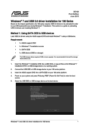
... as the boot device. Power on preloading USB 3.0 drivers and installing Windows® 7. Requirement: • 1 x ASUS support DVD • 1 x Windows® 7 installation source • 1 x SATA ODD • 1 x USB device (ODD or storage) The USB storage device requires 8 GB or more capacity. Method 1: Using SATA ODD & USB devices Load USB 3.0 drivers using the ASUS support DVD and install Windows® 7 using a USB device. Connect the USB ODD or USB storage device to format the storage device before use USB keyboard/mouse during POST (Power-On Self Test) to enter the boot screen...
... as the boot device. Power on preloading USB 3.0 drivers and installing Windows® 7. Requirement: • 1 x ASUS support DVD • 1 x Windows® 7 installation source • 1 x SATA ODD • 1 x USB device (ODD or storage) The USB storage device requires 8 GB or more capacity. Method 1: Using SATA ODD & USB devices Load USB 3.0 drivers using the ASUS support DVD and install Windows® 7 using a USB device. Connect the USB ODD or USB storage device to format the storage device before use USB keyboard/mouse during POST (Power-On Self Test) to enter the boot screen...
Windows 7 and USB 3.0 driver installation for 100 Series.English
Page 2
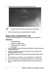
... USB 3.0 driver will show up if the USB 3.0 driver is starting..." screen will be loaded automatically during POST (Power-On Self Test) to your working system, create an ISO image file of the Windows® 7 installation source using a modified Windows® 7 installation DVD. Requirement: • 1 x ASUS support DVD • 1 x Windows® 7 installation source • 1 x Working system (PC or notebook) • 1 x SATA ODD 1. Burn this ISO file onto an empty DVD to complete the Windows® 7 installation. Power...
... USB 3.0 driver will show up if the USB 3.0 driver is starting..." screen will be loaded automatically during POST (Power-On Self Test) to your working system, create an ISO image file of the Windows® 7 installation source using a modified Windows® 7 installation DVD. Requirement: • 1 x ASUS support DVD • 1 x Windows® 7 installation source • 1 x Working system (PC or notebook) • 1 x SATA ODD 1. Burn this ISO file onto an empty DVD to complete the Windows® 7 installation. Power...
Windows 7 and USB 3.0 driver installation for 100 Series.English
Page 3
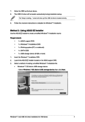
... Requirement: • 1 x ASUS support DVD • 1 x Windows® 7 installation DVD • 1 x Working system (PC or notebook) • 1 x SATA ODD • 1 x USB storage device (8 GB or more) 1. Method 3: Using ASUS EZ Installer Use the ASUS EZ Installer to complete the Windows® 7 installation. 7. The USB 3.0 driver will show up if the USB 3.0 driver is starting..." Launch the ASUS EZ Installer located on the ASUS support DVD. 3. screen will be loaded automatically during installation startup. Insert the Windows® 7 installation DVD. 2. Select a method of...
... Requirement: • 1 x ASUS support DVD • 1 x Windows® 7 installation DVD • 1 x Working system (PC or notebook) • 1 x SATA ODD • 1 x USB storage device (8 GB or more) 1. Method 3: Using ASUS EZ Installer Use the ASUS EZ Installer to complete the Windows® 7 installation. 7. The USB 3.0 driver will show up if the USB 3.0 driver is starting..." Launch the ASUS EZ Installer located on the ASUS support DVD. 3. screen will be loaded automatically during installation startup. Insert the Windows® 7 installation DVD. 2. Select a method of...

Windows 7 and USB 3.0 driver installation for 100 Series.English
Page 6
... or connect the USB storage device with modified Windows® 7 installation files onto your system and press F8 during installation startup. Select the ODD or USB storage device as the boot device. 7. Power on your 100 series platform. 5. Follow the onscreen instructions to create a modified Windows® 7 installation DVD. 4. screen will be loaded automatically during POST (Power-On Self Test) to enter the boot screen. 6. The USB 3.0 driver will show up if the USB 3.0 driver is starting..." The "Setup...
... or connect the USB storage device with modified Windows® 7 installation files onto your system and press F8 during installation startup. Select the ODD or USB storage device as the boot device. 7. Power on your 100 series platform. 5. Follow the onscreen instructions to create a modified Windows® 7 installation DVD. 4. screen will be loaded automatically during POST (Power-On Self Test) to enter the boot screen. 6. The USB 3.0 driver will show up if the USB 3.0 driver is starting..." The "Setup...

VM65 Series user s manual English
Page 2
... DEFECT OR ERROR IN THIS MANUAL OR PRODUCT. SPECIFICATIONS AND INFORMATION CONTAINED IN THIS MANUAL ARE FURNISHED FOR INFORMATIONAL USE ONLY, AND ARE SUBJECT TO CHANGE AT ANY TIME WITHOUT NOTICE, AND SHOULD NOT BE CONSTRUED AS A COMMITMENT BY ASUS. E11598 Revised Edition V2 April 2016 COPYRIGHT INFORMATION No part of this Warranty Statement, up to the listed contract...
... DEFECT OR ERROR IN THIS MANUAL OR PRODUCT. SPECIFICATIONS AND INFORMATION CONTAINED IN THIS MANUAL ARE FURNISHED FOR INFORMATIONAL USE ONLY, AND ARE SUBJECT TO CHANGE AT ANY TIME WITHOUT NOTICE, AND SHOULD NOT BE CONSTRUED AS A COMMITMENT BY ASUS. E11598 Revised Edition V2 April 2016 COPYRIGHT INFORMATION No part of this Warranty Statement, up to the listed contract...
VM65 Series user s manual English
Page 3
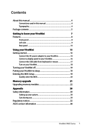
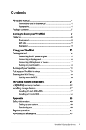
... ...9 Rear panel...10 Using your VivoMini 13 Getting started 14 Connect the AC power adapter to your VivoMini 14 Connect a display panel to your VivoMini 16 Connect the USB cable from keyboard or mouse 17 Turn on your VivoMini 18 Turning your VivoMini off 19 Putting your VivoMini to sleep 19 Entering the BIOS Setup 19 Quickly enter the BIOS 20 Memory upgrade 21 Upgrading memory modules 22 Appendix 29 Safety information 30 Setting up your system 30 Care during use 30 Regulatory notices 32 ASUS...
... ...9 Rear panel...10 Using your VivoMini 13 Getting started 14 Connect the AC power adapter to your VivoMini 14 Connect a display panel to your VivoMini 16 Connect the USB cable from keyboard or mouse 17 Turn on your VivoMini 18 Turning your VivoMini off 19 Putting your VivoMini to sleep 19 Entering the BIOS Setup 19 Quickly enter the BIOS 20 Memory upgrade 21 Upgrading memory modules 22 Appendix 29 Safety information 30 Setting up your system 30 Care during use 30 Regulatory notices 32 ASUS...

VM65 Series user s manual English
Page 8
Before removing the top cover, turn off your VivoMini is accessing the internal storage drive. 8 VivoMini VM65 Series Drive activity indicator This indicator lights up when your VivoMini and unplug the power cable. Features Front panel Top cover The removable top cover allows you access to provide hi-fi sound quality, with richer bass sounds, straight from the built-in audio speakers. IMPORTANT! Audio speakers Your VivoMini uses SonicMaster technology to the hard disk drive and the memory modules.
Before removing the top cover, turn off your VivoMini is accessing the internal storage drive. 8 VivoMini VM65 Series Drive activity indicator This indicator lights up when your VivoMini and unplug the power cable. Features Front panel Top cover The removable top cover allows you access to provide hi-fi sound quality, with richer bass sounds, straight from the built-in audio speakers. IMPORTANT! Audio speakers Your VivoMini uses SonicMaster technology to the hard disk drive and the memory modules.

VM65 Series user s manual English
Page 11
DisplayPort port Use this port may vary per model. LAN port The 8-pin RJ-45 LAN port supports a standard Ethernet cable for video conferencing, voice narrations, or simple audio recordings. Microphone jack The microphone jack is designed to connect the microphone used to connect the system's audio out signal to connect your TV. USB 3.0 ports These Universal Serial Bus 3.0 (USB 3.0) ports provide a transfer rate of this port to amplified speakers or headphones. Digital audio out port (S/PDIF optical) The Sony...
DisplayPort port Use this port may vary per model. LAN port The 8-pin RJ-45 LAN port supports a standard Ethernet cable for video conferencing, voice narrations, or simple audio recordings. Microphone jack The microphone jack is designed to connect the microphone used to connect the system's audio out signal to connect your TV. USB 3.0 ports These Universal Serial Bus 3.0 (USB 3.0) ports provide a transfer rate of this port to amplified speakers or headphones. Digital audio out port (S/PDIF optical) The Sony...

VM65 Series user s manual English
Page 17
Connecting keyboard or mouse via USB 3.0 port VivoMini VM65 Series 17 You can connect generally any of the USB 3.0 ports of your VivoMini. To connect a keyboard and mouse to your VivoMini. Connect the USB cable from your keyboard and mouse to any USB keyboard and mouse to your VivoMini: Connect the USB cable from keyboard or mouse You can also connect a USB dongle for a wireless keyboard and mouse set.
Connecting keyboard or mouse via USB 3.0 port VivoMini VM65 Series 17 You can connect generally any of the USB 3.0 ports of your VivoMini. To connect a keyboard and mouse to your VivoMini. Connect the USB cable from your keyboard and mouse to any USB keyboard and mouse to your VivoMini: Connect the USB cable from keyboard or mouse You can also connect a USB dongle for a wireless keyboard and mouse set.

VM65 Series user s manual English
Page 19
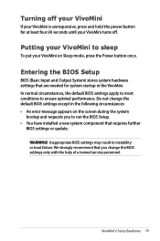
... instability or boot failure. We strongly recommend that you to sleep To put your VivoMini on the screen during the system bootup and requests you change the BIOS settings only with the help of a trained service personnel. Entering the BIOS Setup BIOS (Basic Input and Output System) stores system hardware settings that requires further BIOS settings or update. Turning your VivoMini off . Putting your VivoMini to run the BIOS Setup. • You have installed a new system...
... instability or boot failure. We strongly recommend that you to sleep To put your VivoMini on the screen during the system bootup and requests you change the BIOS settings only with the help of a trained service personnel. Entering the BIOS Setup BIOS (Basic Input and Output System) stores system hardware settings that requires further BIOS settings or update. Turning your VivoMini off . Putting your VivoMini to run the BIOS Setup. • You have installed a new system...
VivoMini V Seriese Barebone User Manual English
Page 2
... No part of this manual, including the products and software described in it, may be registered trademarks or copyrights of their respective companies, and are used only for identification or explanation and to the owners' benefit, without the express written permission of the basis on ASUS' part or other actual and direct damages resulted from omission or failure...
... No part of this manual, including the products and software described in it, may be registered trademarks or copyrights of their respective companies, and are used only for identification or explanation and to the owners' benefit, without the express written permission of the basis on ASUS' part or other actual and direct damages resulted from omission or failure...
VivoMini V Seriese Barebone User Manual English
Page 3
... Getting started 14 Connecting the AC power adapter 14 Connecting a display panel 16 Connecting USB keyboard or mouse 17 Turning on your VivoMini 18 Turning off your VivoMini 19 Putting your VivoMini to sleep 19 Entering the BIOS Setup 19 Quickly enter the BIOS 20 Installing system components 21 Upgrading memory modules 22 Installing storage devices 27 Installing 2.5-inch HDDs/SSDs 27 Installing a 3.5-inch HDD 34 Appendix 39 Safety information 40 Setting up your system 40 Care during use 40 Regulatory notices 42 ASUS...
... Getting started 14 Connecting the AC power adapter 14 Connecting a display panel 16 Connecting USB keyboard or mouse 17 Turning on your VivoMini 18 Turning off your VivoMini 19 Putting your VivoMini to sleep 19 Entering the BIOS Setup 19 Quickly enter the BIOS 20 Installing system components 21 Upgrading memory modules 22 Installing storage devices 27 Installing 2.5-inch HDDs/SSDs 27 Installing a 3.5-inch HDD 34 Appendix 39 Safety information 40 Setting up your system 40 Care during use 40 Regulatory notices 42 ASUS...

VivoMini V Seriese Barebone User Manual English
Page 11
... USB 2.0. VivoMini V Series Barebone 11 USB 3.0 ports These Universal Serial Bus 3.0 (USB 3.0) ports provide a transfer rate of this port to a local network. USB 3.1 ports (on selected models) The USB 3.1 (Universal Serial Bus 3.1) port provides a transfer rate up to amplified speakers or headphones. Microphone jack The microphone jack is backward compatible to a DisplayPort or VGA, DVI, or HDMI external display. NOTE: Transfer rate of up to 10 Gbit/s and is designed to connect...
... USB 2.0. VivoMini V Series Barebone 11 USB 3.0 ports These Universal Serial Bus 3.0 (USB 3.0) ports provide a transfer rate of this port to a local network. USB 3.1 ports (on selected models) The USB 3.1 (Universal Serial Bus 3.1) port provides a transfer rate up to amplified speakers or headphones. Microphone jack The microphone jack is backward compatible to a DisplayPort or VGA, DVI, or HDMI external display. NOTE: Transfer rate of up to 10 Gbit/s and is designed to connect...

VivoMini V Seriese Barebone User Manual English
Page 17
To connect a keyboard and mouse to your VivoMini: Connect the USB cable from your keyboard and mouse to your VivoMini. Connecting keyboard or mouse via USB 3.0 port VivoMini V Series Barebone 17 Connecting USB keyboard or mouse You can also connect a USB dongle for a wireless keyboard and mouse set. You can connect generally any USB keyboard and mouse to any of the USB 3.0 ports of your VivoMini.
To connect a keyboard and mouse to your VivoMini: Connect the USB cable from your keyboard and mouse to your VivoMini. Connecting keyboard or mouse via USB 3.0 port VivoMini V Series Barebone 17 Connecting USB keyboard or mouse You can also connect a USB dongle for a wireless keyboard and mouse set. You can connect generally any USB keyboard and mouse to any of the USB 3.0 ports of your VivoMini.
VivoMini V Seriese Barebone User Manual English
Page 19
... or boot failure. We strongly recommend that you to run the BIOS Setup. • You have installed a new system component that are needed for at least four (4) seconds until your VivoMini on the screen during the system bootup and requests you change the default BIOS settings except in the VivoMini. VivoMini V Series Barebone 19 Turning off your VivoMini If your VivoMini is unresponsive, press and hold the power button for system startup in...
... or boot failure. We strongly recommend that you to run the BIOS Setup. • You have installed a new system component that are needed for at least four (4) seconds until your VivoMini on the screen during the system bootup and requests you change the default BIOS settings except in the VivoMini. VivoMini V Series Barebone 19 Turning off your VivoMini If your VivoMini is unresponsive, press and hold the power button for system startup in...

VivoMini V Seriese Barebone User Manual English
Page 29
8. SATA connector (lower port SATA connector (HDD/SSD) on the lower part of the Vivo DualBay adapter, then slide the 2.5-inch HDD/SSD into the adapter's SATA connector as shown. Slide the top cover of the Vivo DualBay adapter towards the rear, then remove the top cover and set of the 2.5-inch HDD/SSD to the SATA connector on Vivo DualBay adapter) 2.5-inch HDD/SSD Vivo DualBay adapter VivoMini V Series Barebone 29 Prepare a 2.5-inch HDD/SSD and the bundled set it aside. 9. Align the SATA connector of screws. 10.
8. SATA connector (lower port SATA connector (HDD/SSD) on the lower part of the Vivo DualBay adapter, then slide the 2.5-inch HDD/SSD into the adapter's SATA connector as shown. Slide the top cover of the Vivo DualBay adapter towards the rear, then remove the top cover and set of the 2.5-inch HDD/SSD to the SATA connector on Vivo DualBay adapter) 2.5-inch HDD/SSD Vivo DualBay adapter VivoMini V Series Barebone 29 Prepare a 2.5-inch HDD/SSD and the bundled set it aside. 9. Align the SATA connector of screws. 10.

VM65 Series Users manual English
Page 2
... SERVICE AND SUPPORT Visit our multi-language web site at https://www.asus.com/support/ ASUS ASSUMES NO RESPONSIBILITY OR LIABILITY FOR ANY ERRORS OR INACCURACIES THAT MAY APPEAR IN THIS MANUAL, INCLUDING THE PRODUCTS AND SOFTWARE DESCRIBED IN IT. Products and corporate names appearing in this manual may...FROM ANY DEFECT OR ERROR IN THIS MANUAL OR PRODUCT. SPECIFICATIONS AND INFORMATION CONTAINED IN THIS MANUAL ARE FURNISHED FOR INFORMATIONAL USE ONLY, AND ARE SUBJECT TO CHANGE AT ANY TIME WITHOUT NOTICE, AND SHOULD NOT BE CONSTRUED AS A COMMITMENT BY ASUS. LIMITATION OF LIABILITY ...
... SERVICE AND SUPPORT Visit our multi-language web site at https://www.asus.com/support/ ASUS ASSUMES NO RESPONSIBILITY OR LIABILITY FOR ANY ERRORS OR INACCURACIES THAT MAY APPEAR IN THIS MANUAL, INCLUDING THE PRODUCTS AND SOFTWARE DESCRIBED IN IT. Products and corporate names appearing in this manual may...FROM ANY DEFECT OR ERROR IN THIS MANUAL OR PRODUCT. SPECIFICATIONS AND INFORMATION CONTAINED IN THIS MANUAL ARE FURNISHED FOR INFORMATIONAL USE ONLY, AND ARE SUBJECT TO CHANGE AT ANY TIME WITHOUT NOTICE, AND SHOULD NOT BE CONSTRUED AS A COMMITMENT BY ASUS. LIMITATION OF LIABILITY ...

VM65 Series Users manual English
Page 3
... ...9 Rear panel...10 Using your VivoMini 13 Getting started 14 Connect the AC power adapter to your VivoMini 14 Connect a display panel to your VivoMini 16 Connect the USB cable from keyboard or mouse 17 Turn on your VivoMini 18 Turning your VivoMini off 19 Putting your VivoMini to sleep 19 Entering the BIOS Setup 19 Quickly enter the BIOS 20 Memory upgrade 21 Upgrading memory modules 22 Appendix 29 Safety information 30 Setting up your system 30 Care during use 30 Regulatory notices 32 ASUS...
... ...9 Rear panel...10 Using your VivoMini 13 Getting started 14 Connect the AC power adapter to your VivoMini 14 Connect a display panel to your VivoMini 16 Connect the USB cable from keyboard or mouse 17 Turn on your VivoMini 18 Turning your VivoMini off 19 Putting your VivoMini to sleep 19 Entering the BIOS Setup 19 Quickly enter the BIOS 20 Memory upgrade 21 Upgrading memory modules 22 Appendix 29 Safety information 30 Setting up your system 30 Care during use 30 Regulatory notices 32 ASUS...

VM65 Series Users manual English
Page 11
... HDMI external display. Digital audio out port (S/PDIF optical) The Sony/Philips Digital Interface (S/PDIF) optical out port allows you to transfer digital audio from your VivoMini into an amplifier or your ViVoMini to USB 2.0. USB 3.1 ports (on selected models) The USB 3.1 (Universal Serial Bus 3.1) port provides a transfer rate up to amplified speakers or headphones. LAN port The 8-pin RJ-45 LAN port supports a standard Ethernet cable for video conferencing, voice narrations, or simple audio recordings. USB 3.0 ports These Universal Serial Bus 3.0 (USB 3.0) ports...
... HDMI external display. Digital audio out port (S/PDIF optical) The Sony/Philips Digital Interface (S/PDIF) optical out port allows you to transfer digital audio from your VivoMini into an amplifier or your ViVoMini to USB 2.0. USB 3.1 ports (on selected models) The USB 3.1 (Universal Serial Bus 3.1) port provides a transfer rate up to amplified speakers or headphones. LAN port The 8-pin RJ-45 LAN port supports a standard Ethernet cable for video conferencing, voice narrations, or simple audio recordings. USB 3.0 ports These Universal Serial Bus 3.0 (USB 3.0) ports...

VM65 Series Users manual English
Page 17
To connect a keyboard and mouse to your VivoMini. Connecting keyboard or mouse via USB 3.0 port VivoMini VM65 Series 17 Connect the USB cable from your keyboard and mouse to any USB keyboard and mouse to your VivoMini: Connect the USB cable from keyboard or mouse You can also connect a USB dongle for a wireless keyboard and mouse set. You can connect generally any of the USB 3.0 ports of your VivoMini.
To connect a keyboard and mouse to your VivoMini. Connecting keyboard or mouse via USB 3.0 port VivoMini VM65 Series 17 Connect the USB cable from your keyboard and mouse to any USB keyboard and mouse to your VivoMini: Connect the USB cable from keyboard or mouse You can also connect a USB dongle for a wireless keyboard and mouse set. You can connect generally any of the USB 3.0 ports of your VivoMini.


