Vintage-PE1 User''s Manual for English Edition
Page 2
...or altered, unless such repair, modification of the product is authorized in any form or by any means, except documentation kept by ASUS; ASUS PROVIDES THIS MANUAL "AS IS" WITHOUT WARRANTY OF ANY KIND, EITHER EXPRESS OR IMPLIED, INCLUDING BUT NOT LIMITED TO THE IMPLIED WARRANTIES...OF MERCHANTABILITY OR FITNESS FOR A PARTICULAR PURPOSE. E2012 First Edition April 2005 Copyright © 2005 ASUSTeK COMPUTER INC. IN NO EVENT SHALL ASUS, ITS DIRECTORS, OFFICERS, EMPLOYEES OR AGENTS BE LIABLE FOR ANY INDIRECT, SPECIAL, INCIDENTAL, OR CONSEQUENTIAL DAMAGES (INCLUDING DAMAGES FOR LOSS OF ...
...or altered, unless such repair, modification of the product is authorized in any form or by any means, except documentation kept by ASUS; ASUS PROVIDES THIS MANUAL "AS IS" WITHOUT WARRANTY OF ANY KIND, EITHER EXPRESS OR IMPLIED, INCLUDING BUT NOT LIMITED TO THE IMPLIED WARRANTIES...OF MERCHANTABILITY OR FITNESS FOR A PARTICULAR PURPOSE. E2012 First Edition April 2005 Copyright © 2005 ASUSTeK COMPUTER INC. IN NO EVENT SHALL ASUS, ITS DIRECTORS, OFFICERS, EMPLOYEES OR AGENTS BE LIABLE FOR ANY INDIRECT, SPECIAL, INCIDENTAL, OR CONSEQUENTIAL DAMAGES (INCLUDING DAMAGES FOR LOSS OF ...

Vintage-PE1 User''s Manual for English Edition
Page 3
Table of contents Notices vii Safety information vii About this guide viii System package contents x Chapter 1: System Introduction 1.1 Welcome 1-2 1.2 Front panel 1-2 1.3 Rear panel 1-4 Voltage selector 1-6 1.4 Internal components 1-7 Chapter 2: Basic Installation 2.1 Preparation 2-2 2.2 Before you proceed 2-2 2.3 Removing the side plate and front cover 2-3 2.4 Central Processing Unit (CPU 2-5 2.4.1 Installling the CPU 2-5 2.4.2 Installling the CPU heatsink and fan 2-8 2.4.3 Uninstalling the CPU heatsink and fan 2-10 2.5 Installing a DIMM 2-12 2.5.1 Memory configurations 2-...
Table of contents Notices vii Safety information vii About this guide viii System package contents x Chapter 1: System Introduction 1.1 Welcome 1-2 1.2 Front panel 1-2 1.3 Rear panel 1-4 Voltage selector 1-6 1.4 Internal components 1-7 Chapter 2: Basic Installation 2.1 Preparation 2-2 2.2 Before you proceed 2-2 2.3 Removing the side plate and front cover 2-3 2.4 Central Processing Unit (CPU 2-5 2.4.1 Installling the CPU 2-5 2.4.2 Installling the CPU heatsink and fan 2-8 2.4.3 Uninstalling the CPU heatsink and fan 2-10 2.5 Installing a DIMM 2-12 2.5.1 Memory configurations 2-...
Vintage-PE1 User''s Manual for English Edition
Page 4
... information 3-5 Chapter 4: Motherboard Info 4.1 Introduction 4-2 4.2 Motherboard layout 4-2 4.3 Jumpers 4-3 4.4 Connectors 4-5 Chapter 5: BIOS Information 5.1 Managing and updating your BIOS 5-2 5.1.1 Creating a bootable floppy disk 5-2 5.1.2 ASUS EZ Flash utility 5-3 5.1.3 AFUDOS utility 5-4 5.1.4 ASUS CrashFree BIOS 2 utility 5-6 5.1.5 ASUS Update utility 5-8 5.2 BIOS setup program 5-11 5.2.1 BIOS menu screen 5-12 5.2.2 Menu bar 5-12 5.2.3 Navigation keys 5-12 5.2.4 Menu items 5-13 5.2.5 Sub-menu...
... information 3-5 Chapter 4: Motherboard Info 4.1 Introduction 4-2 4.2 Motherboard layout 4-2 4.3 Jumpers 4-3 4.4 Connectors 4-5 Chapter 5: BIOS Information 5.1 Managing and updating your BIOS 5-2 5.1.1 Creating a bootable floppy disk 5-2 5.1.2 ASUS EZ Flash utility 5-3 5.1.3 AFUDOS utility 5-4 5.1.4 ASUS CrashFree BIOS 2 utility 5-6 5.1.5 ASUS Update utility 5-8 5.2 BIOS setup program 5-11 5.2.1 BIOS menu screen 5-12 5.2.2 Menu bar 5-12 5.2.3 Navigation keys 5-12 5.2.4 Menu items 5-13 5.2.5 Sub-menu...

Vintage-PE1 User''s Manual for English Edition
Page 5
Table of contents 5.3.4 Primary and Secondary IDE Master/Slave 5-15 5.3.5 OnChip SATA Controller 5-16 5.3.6 System Information 5-16 5.4 Advanced menu 5-17 5.4.1 JumperFree Configuration 5-17 5.4.2 CPU Configuration 5-18 5.4.3 Chipset 5-19 5.4.4 Onboard Devices Configuration 5-20 5.4.5 PCI PnP 5-22 5.4.6 USB Configuration 5-23 5.4.7 Instant Music Configuration 5-24 5.5 Power menu 5-25 5.5.1 Suspend Mode 5-25 5.5.2 ACPI 2.0 Support 5-25 5.5.3 ACPI APIC Support 5-25 5.5.5 APM Configuration 5-26 5.5.6 Hardware Monitor 5-27 5.6 Boot menu 5-29 5.6.1 Boot Device Priority 5-29 5.6.2...
Table of contents 5.3.4 Primary and Secondary IDE Master/Slave 5-15 5.3.5 OnChip SATA Controller 5-16 5.3.6 System Information 5-16 5.4 Advanced menu 5-17 5.4.1 JumperFree Configuration 5-17 5.4.2 CPU Configuration 5-18 5.4.3 Chipset 5-19 5.4.4 Onboard Devices Configuration 5-20 5.4.5 PCI PnP 5-22 5.4.6 USB Configuration 5-23 5.4.7 Instant Music Configuration 5-24 5.5 Power menu 5-25 5.5.1 Suspend Mode 5-25 5.5.2 ACPI 2.0 Support 5-25 5.5.3 ACPI APIC Support 5-25 5.5.5 APM Configuration 5-26 5.5.6 Hardware Monitor 5-27 5.6 Boot menu 5-29 5.6.1 Boot Device Priority 5-29 5.6.2...
Vintage-PE1 User''s Manual for English Edition
Page 6
The use of shielded cables for connection of the monitor to the graphics card is connected. • Consult the dealer or an experienced radio/TV technician for help. This equipment generates, uses and can be determined by turning the equipment off and on a circuit different from digital apparatus set out in a residential installation. However, there is subject to the following measures: • Reorient or relocate the receiving antenna. • Increase the separation between the equipment and receiver. • Connect the equipment to an outlet on , the user is encouraged to try ...
The use of shielded cables for connection of the monitor to the graphics card is connected. • Consult the dealer or an experienced radio/TV technician for help. This equipment generates, uses and can be determined by turning the equipment off and on a circuit different from digital apparatus set out in a residential installation. However, there is subject to the following measures: • Reorient or relocate the receiving antenna. • Increase the separation between the equipment and receiver. • Connect the equipment to an outlet on , the user is encouraged to try ...
Vintage-PE1 User''s Manual for English Edition
Page 7
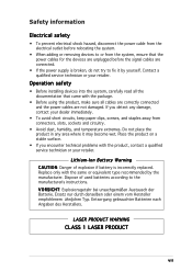
Do not place the product in any damage, contact your dealer immediately. • To avoid short circuits, keep paper clips, screws, and staples away from connectors, slots, sockets and circuitry. • Avoid dust, humidity, and temperature extremes. Dispose of explosion if battery is broken, do not try to fix it may become wet. V O R S I O N: Danger of used batteries according to or from the system, ensure that came with the package. • Before using the product, make sure all cables are correctly connected and the power cables are connected. • If the power supply is...
Do not place the product in any damage, contact your dealer immediately. • To avoid short circuits, keep paper clips, screws, and staples away from connectors, slots, sockets and circuitry. • Avoid dust, humidity, and temperature extremes. Dispose of explosion if battery is broken, do not try to fix it may become wet. V O R S I O N: Danger of used batteries according to or from the system, ensure that came with the package. • Before using the product, make sure all cables are correctly connected and the power cables are connected. • If the power supply is...
Vintage-PE1 User''s Manual for English Edition
Page 8
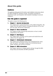
... guide Audience This guide provides general information and installation instructions about the motherboard that comes with hardware knowledge of the ASUS Vintage-PE1. The chapter lists the system features, including introduction on how to change system settings through the BIOS Setup menus ...and describes the BIOS parameters. Chapter 4: Motherboard information This chapter gives information about the ASUS Vintage-PE1 barebone system. viii Chapter 5: BIOS information This chapter tells how to install components in the system. 3. This guide...
... guide Audience This guide provides general information and installation instructions about the motherboard that comes with hardware knowledge of the ASUS Vintage-PE1. The chapter lists the system features, including introduction on how to change system settings through the BIOS Setup menus ...and describes the BIOS parameters. Chapter 4: Motherboard information This chapter gives information about the ASUS Vintage-PE1 barebone system. viii Chapter 5: BIOS information This chapter tells how to install components in the system. 3. This guide...

Vintage-PE1 User''s Manual for English Edition
Page 9
N O T E : Tips and additional information to the ASUS contact information. 2. Refer to aid in this guide W A R N I N G : Information to prevent injury to yourself when trying to complete a task. ... A U T I M P O R T A N T : Instructions that may include optional documentation, such as warranty flyers, that you MUST follow to complete a task. ASUS Websites The ASUS websites worldwide provide updated information on ASUS hardware and software products. Conventions used in completing a task. I O N : Information to prevent damage to the components when trying to the following...
N O T E : Tips and additional information to the ASUS contact information. 2. Refer to aid in this guide W A R N I N G : Information to prevent injury to yourself when trying to complete a task. ... A U T I M P O R T A N T : Instructions that may include optional documentation, such as warranty flyers, that you MUST follow to complete a task. ASUS Websites The ASUS websites worldwide provide updated information on ASUS hardware and software products. Conventions used in completing a task. I O N : Information to prevent damage to the components when trying to the following...
Vintage-PE1 User''s Manual for English Edition
Page 10
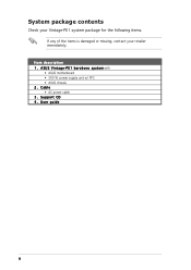
Item description 1 . User guide x Cable • AC power cable 3 . Support CD 4 . P E 1 b a r e b o n e s y s t e m with • ASUS motherboard • 300 W power supply unit w/ PFC • ASUS chassis 2. A S U S V i n t a g e - System package contents Check your Vintage-PE1 system package for the following items. If any of the items is damaged or missing, contact your retailer immediately.
Item description 1 . User guide x Cable • AC power cable 3 . Support CD 4 . P E 1 b a r e b o n e s y s t e m with • ASUS motherboard • 300 W power supply unit w/ PFC • ASUS chassis 2. A S U S V i n t a g e - System package contents Check your Vintage-PE1 system package for the following items. If any of the items is damaged or missing, contact your retailer immediately.
Vintage-PE1 User''s Manual for English Edition
Page 11
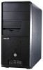
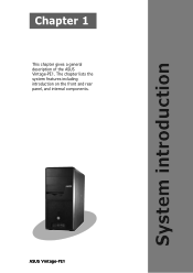
ASUS Vintage-PE1 The chapter lists the system features including introduction on the front and rear panel, and internal components. System introduction Chapter 1 This chapter gives a general description of the ASUS Vintage-PE1.
ASUS Vintage-PE1 The chapter lists the system features including introduction on the front and rear panel, and internal components. System introduction Chapter 1 This chapter gives a general description of the ASUS Vintage-PE1.
Vintage-PE1 User''s Manual for English Edition
Page 12
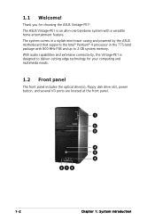
...are located at the front panel. 1 2 3 4 5 9 67 8 1-2 Chapter 1: System introduction The ASUS Vintage-PE1 is designed to 2 GB system memory. With audio capabilities and extensive connectivity, the Vintage-PE1 is an all-in the 775-land package with a versatile home entertainment feature. 1.1 Welcome! The system comes ...in a stylish mini-tower casing and powered by the ASUS motherboard that supports the Intel® Pentium® 4 processor in -one barebone system with 800 MHz FSB and up to deliver cutting edge technology for choosing the ASUS Vintage-PE1!
...are located at the front panel. 1 2 3 4 5 9 67 8 1-2 Chapter 1: System introduction The ASUS Vintage-PE1 is designed to 2 GB system memory. With audio capabilities and extensive connectivity, the Vintage-PE1 is an all-in the 775-land package with a versatile home entertainment feature. 1.1 Welcome! The system comes ...in a stylish mini-tower casing and powered by the ASUS motherboard that supports the Intel® Pentium® 4 processor in -one barebone system with 800 MHz FSB and up to deliver cutting edge technology for choosing the ASUS Vintage-PE1!
Vintage-PE1 User''s Manual for English Edition
Page 13
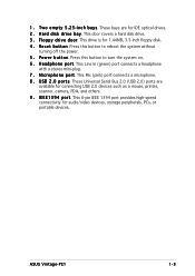
1 . This drive is for audio/video devices, storage peripherals, PCs, or portable devices. P o w e r b u t t o n. Press this button to turn the system on. 6 . ASUS Vintage-PE1 1-3 T w o e m p t y 5 . 2 5 - Press this button to reboot the system without turning off the power. 5 . U S B 2 . 0 p o r t s. This 6-pin IEEE 1394 port provides high-speed connectivity for 1.44MB, 3.5-inch floppy ...
1 . This drive is for audio/video devices, storage peripherals, PCs, or portable devices. P o w e r b u t t o n. Press this button to turn the system on. 6 . ASUS Vintage-PE1 1-3 T w o e m p t y 5 . 2 5 - Press this button to reboot the system without turning off the power. 5 . U S B 2 . 0 p o r t s. This 6-pin IEEE 1394 port provides high-speed connectivity for 1.44MB, 3.5-inch floppy ...

Vintage-PE1 User''s Manual for English Edition
Page 14
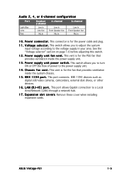
This 25-pin port connects a printer, scanner, or other audio sources. 1-4 Chapter 1: System introduction This port connects a microphone. 8 . In 4-channel, 6-channel, and 8-channel configuration, the function of devices. 10 11 12 1 13 2 3 14 4 15 5 16 6 7 17 8 9 1 . S e r i a l p o r t . U S B 2 . 0 p o r t s 1 , 2 , 3 a n d 4 . P S / 2 k e y b o a r d p o r t. This purple 6-pin connector is for a PS/2 keyboard. 2 . This port connects a VGA monitor. 6 . M i c r o p h o n e p o r t ( p i n k ) . L i n e O u t p o r t ( l i m e ) . P S / 2 m o u s e p o r ...
This 25-pin port connects a printer, scanner, or other audio sources. 1-4 Chapter 1: System introduction This port connects a microphone. 8 . In 4-channel, 6-channel, and 8-channel configuration, the function of devices. 10 11 12 1 13 2 3 14 4 15 5 16 6 7 17 8 9 1 . S e r i a l p o r t . U S B 2 . 0 p o r t s 1 , 2 , 3 a n d 4 . P S / 2 k e y b o a r d p o r t. This purple 6-pin connector is for a PS/2 keyboard. 2 . This port connects a VGA monitor. 6 . M i c r o p h o n e p o r t ( p i n k ) . L i n e O u t p o r t ( l i m e ) . P S / 2 m o u s e p o r ...
Vintage-PE1 User''s Manual for English Edition
Page 15
... Speaker Out Mic In 6-channel Line In Front Speaker Out Mic In 1 0 . This connector is for the fan that provides ventilation inside the system chassis. 1 5 . C h a s s i s f a n v e n t . L A N ( R J - 4 5 ) p o r t . ASUS Vintage-PE1 1-5 This switch allows you to turn ON or OFF the flow of power to the power supply unit. 1 4 . This vent is for the power cable...
... Speaker Out Mic In 6-channel Line In Front Speaker Out Mic In 1 0 . This connector is for the fan that provides ventilation inside the system chassis. 1 5 . C h a s s i s f a n v e n t . L A N ( R J - 4 5 ) p o r t . ASUS Vintage-PE1 1-5 This switch allows you to turn ON or OFF the flow of power to the power supply unit. 1 4 . This vent is for the power cable...

Vintage-PE1 User''s Manual for English Edition
Page 16
Use this switch to select the appropriate system input voltage according to the voltage supply in your area is 200-240 V, set the switch to 115V in a 230V environment or 230V in a 115V environment will seriously damage the system! 1-6 Chapter 1: System introduction If the voltage supply in your area is 100-127 V, set the switch to 230 V. 115V/230V Voltage selector Setting the switch to 115 V. If the voltage supply in your area. Voltage selector The PSU has a 115 V/230 V voltage selector switch located beside the power connector.
Use this switch to select the appropriate system input voltage according to the voltage supply in your area is 200-240 V, set the switch to 115V in a 230V environment or 230V in a 115V environment will seriously damage the system! 1-6 Chapter 1: System introduction If the voltage supply in your area is 100-127 V, set the switch to 230 V. 115V/230V Voltage selector Setting the switch to 115 V. If the voltage supply in your area. Voltage selector The PSU has a 115 V/230 V voltage selector switch located beside the power connector.
Vintage-PE1 User''s Manual for English Edition
Page 17
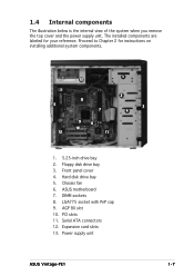
... on installing additional system components. 1 13 2 8 5 3 7 4 9 6 10 12 11 1. 5.25-inch drive bay 2. PCI slots 11. Hard disk drive bay 5. Chassis fan 6. Power supply unit ASUS Vintage-PE1 1-7 Expansion card slots 13. 1.4 Internal components The illustration below is the internal view of the system when you remove the top cover and the power...
... on installing additional system components. 1 13 2 8 5 3 7 4 9 6 10 12 11 1. 5.25-inch drive bay 2. PCI slots 11. Hard disk drive bay 5. Chassis fan 6. Power supply unit ASUS Vintage-PE1 1-7 Expansion card slots 13. 1.4 Internal components The illustration below is the internal view of the system when you remove the top cover and the power...
Vintage-PE1 User''s Manual for English Edition
Page 19
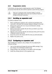
...). 3. Remove the system unit cover (if your motherboard is completely seated on BIOS setup. 2. Keep the screw for the card. 2. Turn on the next page. 3. ASUS Vintage-PE1 2-15 Align the card connector with it by adjusting the software settings. 1. 2.6 Expansion slots In the future, you may cause you physical injury and damage...
...). 3. Remove the system unit cover (if your motherboard is completely seated on BIOS setup. 2. Keep the screw for the card. 2. Turn on the next page. 3. ASUS Vintage-PE1 2-15 Align the card connector with it by adjusting the software settings. 1. 2.6 Expansion slots In the future, you may cause you physical injury and damage...
Vintage-PE1 User''s Manual for English Edition
Page 20
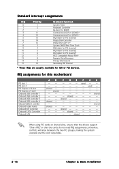
Standard interrupt assignments IRQ Priority 0 1 1 2 2 - 3 11 4 12 5 13 6 14 7 15 8 3 9 4 10 5 11 6 12 7 13 8 14 9 15 10 Standard Function System Timer Keyboard Controller Re-direct to IRQ#9 Communications Port (COM2)* Communications Port (COM1)* IRQ holder for PCI steering* Floppy Disk Controller Printer Port (LPT1)* System CMOS/Real Time Clock IRQ holder for PCI steering* IRQ holder for PCI steering* IRQ holder for PCI steering* PS/2 Compatible Mouse Port* Numeric Data Processor Primary IDE Channel Secondary IDE Channel * These IRQs are usually available ...
Standard interrupt assignments IRQ Priority 0 1 1 2 2 - 3 11 4 12 5 13 6 14 7 15 8 3 9 4 10 5 11 6 12 7 13 8 14 9 15 10 Standard Function System Timer Keyboard Controller Re-direct to IRQ#9 Communications Port (COM2)* Communications Port (COM1)* IRQ holder for PCI steering* Floppy Disk Controller Printer Port (LPT1)* System CMOS/Real Time Clock IRQ holder for PCI steering* IRQ holder for PCI steering* IRQ holder for PCI steering* PS/2 Compatible Mouse Port* Numeric Data Processor Primary IDE Channel Secondary IDE Channel * These IRQs are usually available ...
Vintage-PE1 User''s Manual for English Edition
Page 21
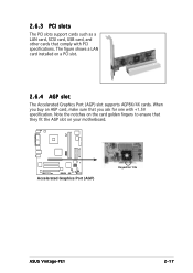
Note the notches on the card golden fingers to ensure that you buy an AGP card, make sure that they fit the AGP slot on a PCI slot. 2.6.4 AGP slot The Accelerated Graphics Port (AGP) slot supports AGP8X/4X cards. When you ask for 1.5v ASUS Vintage-PE1 2-17 2.6.3 PCI slots The PCI slots support cards such as a LAN card, SCSI card, USB card, and other cards that comply with +1.5V specification. The figure shows a LAN card installed on your motherboard. ® Accelerated Graphics Port (AGP) Keyed for one with PCI specifications.
Note the notches on the card golden fingers to ensure that you buy an AGP card, make sure that they fit the AGP slot on a PCI slot. 2.6.4 AGP slot The Accelerated Graphics Port (AGP) slot supports AGP8X/4X cards. When you ask for 1.5v ASUS Vintage-PE1 2-17 2.6.3 PCI slots The PCI slots support cards such as a LAN card, SCSI card, USB card, and other cards that comply with +1.5V specification. The figure shows a LAN card installed on your motherboard. ® Accelerated Graphics Port (AGP) Keyed for one with PCI specifications.

Vintage-PE1 User''s Manual for English Edition
Page 22
2.7 Installing an optical drive The optical drive is an optional item in this desktop system. Carefully push the optical drive into the upper 5.25-inch drive bay. 3. Insert the optical drive into the bay until its screw holes align with two screws on the bay as shown. 4. Place the chassis upright. 2. Follow these steps to the instructions in this section if you acquired a model without an optical drive. Screw holes Screws 2-18 Chapter 2: Basic installation Refer to install an optical drive. 1. Secure the optical drive with the holes on both sides of the bay.
2.7 Installing an optical drive The optical drive is an optional item in this desktop system. Carefully push the optical drive into the upper 5.25-inch drive bay. 3. Insert the optical drive into the bay until its screw holes align with two screws on the bay as shown. 4. Place the chassis upright. 2. Follow these steps to the instructions in this section if you acquired a model without an optical drive. Screw holes Screws 2-18 Chapter 2: Basic installation Refer to install an optical drive. 1. Secure the optical drive with the holes on both sides of the bay.