
User Guide
Page 14
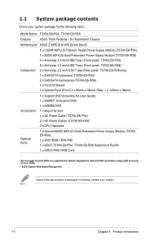
... Name TS700-E8-PS4, TS700-E8-RS8 Chassis ASUS T50A Pedestal / 5U Rackmount Chassis Motherboard ASUS Z10PE-D16 WS Server Board 1 x 1200W 80PLUS Platinum Single Power Supply Module (TS700-E8-PS4) 1 x 800W 80PLUS Gold Redundant Power Supply Module (TS700-E8-RS8) 4 x Hot-swap 3.5-inch HDD Trays (Front panel, TS700-E8-PS4) 8 x Hot-swap 3.5-inch HDD Trays (Front panel, TS700-E8-RS8)* Component 2 x Hot-swap 2.5-inch SSD Trays (Rear panel, TS700-E8-RS8 only...
... Name TS700-E8-PS4, TS700-E8-RS8 Chassis ASUS T50A Pedestal / 5U Rackmount Chassis Motherboard ASUS Z10PE-D16 WS Server Board 1 x 1200W 80PLUS Platinum Single Power Supply Module (TS700-E8-PS4) 1 x 800W 80PLUS Gold Redundant Power Supply Module (TS700-E8-RS8) 4 x Hot-swap 3.5-inch HDD Trays (Front panel, TS700-E8-PS4) 8 x Hot-swap 3.5-inch HDD Trays (Front panel, TS700-E8-RS8)* Component 2 x Hot-swap 2.5-inch SSD Trays (Rear panel, TS700-E8-RS8 only...

User Guide
Page 15
1.2 Serial number label Before requesting support from the ASUS Technical Support team, you must take note of the product, ASUS Technical Support team members can then offer a quicker and satisfying solution to your problems. TS700-E8-PS4 xxS0xxxxxxxxxx TS700-E8-RS8 xxS0xxxxxxxxxx ASUS TS700-E8-PS4, TS700-E8-RS8 1-3 With the correct serial number of the product's serial number containing 14 characters such as xxS0xxxxxxxxxx shown as the figure below.
1.2 Serial number label Before requesting support from the ASUS Technical Support team, you must take note of the product, ASUS Technical Support team members can then offer a quicker and satisfying solution to your problems. TS700-E8-PS4 xxS0xxxxxxxxxx TS700-E8-RS8 xxS0xxxxxxxxxx ASUS TS700-E8-PS4, TS700-E8-RS8 1-3 With the correct serial number of the product's serial number containing 14 characters such as xxS0xxxxxxxxxx shown as the figure below.

User Guide
Page 16
... NVDIMM Memory Type Refer to www.asus.com for the latest memory AVL update. 32GB, 16GB, 8GB and 4GB (RDIMM) Memory Size 64GB, 32GB (LRDIMM) Refer to www.asus.com for Windows only; 1.3 System specifications The ASUS TS700-E8-PS4, TS700-E8-RS8 is a Pedestal / 5U Rackmount ...barebone server system featuring the ASUS Z10PE-D16 WS Server Board. Expansion Slots (follow Total Slots PCI/PCI-E ...
... NVDIMM Memory Type Refer to www.asus.com for the latest memory AVL update. 32GB, 16GB, 8GB and 4GB (RDIMM) Memory Size 64GB, 32GB (LRDIMM) Refer to www.asus.com for Windows only; 1.3 System specifications The ASUS TS700-E8-PS4, TS700-E8-RS8 is a Pedestal / 5U Rackmount ...barebone server system featuring the ASUS Z10PE-D16 WS Server Board. Expansion Slots (follow Total Slots PCI/PCI-E ...

User Guide
Page 17
... CentOS Unbuntu VMWare Citrix XenServer Management Solution Software Out of Band Remote Management * Support versions are subject to change without notice. ASUS TS700-E8-PS4, TS700-E8-RS8 1-5 Model Name Auxiliary Storage Device Bay (Floppy / Optical Drive) TS700-E8-PS4 3 x 5.25" media bays (Options: No Device / DVD-RW) 1 x PS/2 keyboard/mouse combo port 1 x Q-Code Logger button with LED 1 x BIOS Flashback...
... CentOS Unbuntu VMWare Citrix XenServer Management Solution Software Out of Band Remote Management * Support versions are subject to change without notice. ASUS TS700-E8-PS4, TS700-E8-RS8 1-5 Model Name Auxiliary Storage Device Bay (Floppy / Optical Drive) TS700-E8-PS4 3 x 5.25" media bays (Options: No Device / DVD-RW) 1 x PS/2 keyboard/mouse combo port 1 x Q-Code Logger button with LED 1 x BIOS Flashback...

User Guide
Page 18
... features Message LED HDD access LED Power LED Optical drive (optional) 2 x Empty 5.25-inch bays 1 2 4-bay HDD module (First set*) 4-bay HDD module (Second set, TS700-E8-RS8 only**) LAN1 LED LAN2 LED Location LED (Reserved) Security lock Power button Reset button USB BIOS Flashback SPDIF OUT Management USB3.0 USB3.0 side rear c/sub... 3.0 ports • Refer to the 1.7.1 Front panel LEDs section for the LED descriptions. • * Only the first set of 4-bay HDD module is provided on TS700-E8-PS4. • ** For TS700-E8-RS8, six hot-swap 3.5-inch HDDs are supported by default.
... features Message LED HDD access LED Power LED Optical drive (optional) 2 x Empty 5.25-inch bays 1 2 4-bay HDD module (First set*) 4-bay HDD module (Second set, TS700-E8-RS8 only**) LAN1 LED LAN2 LED Location LED (Reserved) Security lock Power button Reset button USB BIOS Flashback SPDIF OUT Management USB3.0 USB3.0 side rear c/sub... 3.0 ports • Refer to the 1.7.1 Front panel LEDs section for the LED descriptions. • * Only the first set of 4-bay HDD module is provided on TS700-E8-PS4. • ** For TS700-E8-RS8, six hot-swap 3.5-inch HDDs are supported by default.

User Guide
Page 19
LAN port 3 LAN port 1 ASUS TS700-E8-PS4, TS700-E8-RS8 1-7 1.5 Rear panel features TS700-E8-PS4 Power connector PS/2 keyboard/ mouse combo port 2 x USB 2.0 ports BIOS Flashback button with LED 2 x USB 2.0 ports 4 x USB 3.0 ports Audio I/O ports USB BIOS Flashback SPDIF OUT Management USB3.0 USB3.0 side rear c/sub MIC IN LINE OUT LINE IN KY Q-Code Logger VGA port 120mm x 38mm system fan Q-Code Logger button with LED SPDIF Out port Management LAN port* LAN (RJ-45) port 2 LAN (RJ-45) port 1 Expansion slots * This port is for ASUS ASMB8-iKVM controller and for techincians only.
LAN port 3 LAN port 1 ASUS TS700-E8-PS4, TS700-E8-RS8 1-7 1.5 Rear panel features TS700-E8-PS4 Power connector PS/2 keyboard/ mouse combo port 2 x USB 2.0 ports BIOS Flashback button with LED 2 x USB 2.0 ports 4 x USB 3.0 ports Audio I/O ports USB BIOS Flashback SPDIF OUT Management USB3.0 USB3.0 side rear c/sub MIC IN LINE OUT LINE IN KY Q-Code Logger VGA port 120mm x 38mm system fan Q-Code Logger button with LED SPDIF Out port Management LAN port* LAN (RJ-45) port 2 LAN (RJ-45) port 1 Expansion slots * This port is for ASUS ASMB8-iKVM controller and for techincians only.

User Guide
Page 21
... includes the basic components as shown. 1. 1200W 80PLUS Platinum Single Power Supply Module (TS700-E8-PS4) or 800W 80PLUS Gold 1+1 Redundant Power Supply Module (TS700-E8-RS8) 2. 120mm x 38mm system fan 3. Expansion card locks 6. The barebone server does not include a floppy disk drive drive. ASUS Z10PE-D16 WS Server Board 4. Connect a USB floppy disk drive to any...
... includes the basic components as shown. 1. 1200W 80PLUS Platinum Single Power Supply Module (TS700-E8-PS4) or 800W 80PLUS Gold 1+1 Redundant Power Supply Module (TS700-E8-RS8) 2. 120mm x 38mm system fan 3. Expansion card locks 6. The barebone server does not include a floppy disk drive drive. ASUS Z10PE-D16 WS Server Board 4. Connect a USB floppy disk drive to any...

User Guide
Page 23
Q-Code Logger USB BIOS Flashback 1.7.2 SPDIF OUT LAN (RJ-45) LEDs Management USB3.0 USB3.0 ACT/LINKsideLEDrear c/sub Status Description OFF No link MIC IN LINE OUT LINE IN ORANGE BLINKING Linked KY Data activity ACT/LINK LED SPEED LED ACT/LINK LED SPEED LED SPEED LED Status Description OFF 10 Mbps connection ORANGE 100 Mbps connection GREEN 1 Gbps connection ASUS TS700-E8-PS4, TS700-E8-RS8 1-11
Q-Code Logger USB BIOS Flashback 1.7.2 SPDIF OUT LAN (RJ-45) LEDs Management USB3.0 USB3.0 ACT/LINKsideLEDrear c/sub Status Description OFF No link MIC IN LINE OUT LINE IN ORANGE BLINKING Linked KY Data activity ACT/LINK LED SPEED LED ACT/LINK LED SPEED LED SPEED LED Status Description OFF 10 Mbps connection ORANGE 100 Mbps connection GREEN 1 Gbps connection ASUS TS700-E8-PS4, TS700-E8-RS8 1-11

User Guide
Page 27
Drive in place. 3. Match and insert the lower sliding edge of the side cover to secure the side cover. 1 3 1 2 3 ASUS TS700-E8-PS4, TS700-E8-RS8 2-3 2.1.2 Reinstalling the side cover To reinstall the side cover: 1. Slide the side cover toward the front panel until it snaps in the two screws you removed earlier to the corresponding chassis edge. 2.
Drive in place. 3. Match and insert the lower sliding edge of the side cover to secure the side cover. 1 3 1 2 3 ASUS TS700-E8-PS4, TS700-E8-RS8 2-3 2.1.2 Reinstalling the side cover To reinstall the side cover: 1. Slide the side cover toward the front panel until it snaps in the two screws you removed earlier to the corresponding chassis edge. 2.
User Guide
Page 29
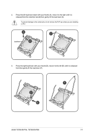
Press the left (E) until it is released from then gently lift the load lever (F). Load lever 3. ASUS TS700-E8-PS4, TS700-E8-RS8 2-5 To prevent damage to the right until it is released from the retention tab (B) then gently lift the load lever (C). 2. Press the right load lever with your thumb (D), move it to the left load lever down with your thumb (A), move it to the socket pins, do not remove the PnP cap unless you are installing a CPU.
Press the left (E) until it is released from then gently lift the load lever (F). Load lever 3. ASUS TS700-E8-PS4, TS700-E8-RS8 2-5 To prevent damage to the right until it is released from the retention tab (B) then gently lift the load lever (C). 2. Press the right load lever with your thumb (D), move it to the left load lever down with your thumb (A), move it to the socket pins, do not remove the PnP cap unless you are installing a CPU.

User Guide
Page 31
Retention tab ASUS TS700-E8-PS4, TS700-E8-RS8 2-7 Push down the left load lever (L) then insert it under the retention tab (K). Keep the PnP cap. ASUS will process Return Merchandise Authorization (RMA) requests only if the motherboard comes with the PnP cap on the LGA 2011 socket. The PnP cap pops ...
Retention tab ASUS TS700-E8-PS4, TS700-E8-RS8 2-7 Push down the left load lever (L) then insert it under the retention tab (K). Keep the PnP cap. ASUS will process Return Merchandise Authorization (RMA) requests only if the motherboard comes with the PnP cap on the LGA 2011 socket. The PnP cap pops ...
User Guide
Page 33
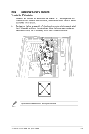
... (cross) screwdriver just enough to attach the CPU heatsink and fan to completely secure the CPU heatsink and fan. Twist each of the server chassis. 2. ASUS TS700-E8-PS4, TS700-E8-RS8 2-9 A B B A Tighten the four heatsink screws in a diagonal sequence. When the four screws are attached, tighten them one by one to the motherboard...
... (cross) screwdriver just enough to attach the CPU heatsink and fan to completely secure the CPU heatsink and fan. Twist each of the server chassis. 2. ASUS TS700-E8-PS4, TS700-E8-RS8 2-9 A B B A Tighten the four heatsink screws in a diagonal sequence. When the four screws are attached, tighten them one by one to the motherboard...

User Guide
Page 35
... (CPU2) A2 A1 B2 B1 C2 C1 D2 D1 E2 E1 F2 F1 G2 G1 H2 H1 2 DIMMs P P 4 DIMMs P P P P 8 DIMMs P P P P P P P P 12 DIMMs P P P P P PPPPP P P 16 DIMMs P P P P P P P P P P P P P P P P ASUS TS700-E8-PS4, TS700-E8-RS8 2-11 Single CPU configuration You can refer to the following recommended memory population for a single CPU configuration.
... (CPU2) A2 A1 B2 B1 C2 C1 D2 D1 E2 E1 F2 F1 G2 G1 H2 H1 2 DIMMs P P 4 DIMMs P P P P 8 DIMMs P P P P P P P P 12 DIMMs P P P P P PPPPP P P 16 DIMMs P P P P P P P P P P P P P P P P ASUS TS700-E8-PS4, TS700-E8-RS8 2-11 Single CPU configuration You can refer to the following recommended memory population for a single CPU configuration.

User Guide
Page 37
..., you should first remove the front panel assembly (front bezel and front panel cover). 2.4.1 Removing the front panel assembly To remove the front panel assembly 1. ASUS TS700-E8-PS4, TS700-E8-RS8 2-13 Locate the three hooked tabs on the chassis side rail. 2. Swing the front panel assembly and snap it back into place. Hook the other...
..., you should first remove the front panel assembly (front bezel and front panel cover). 2.4.1 Removing the front panel assembly To remove the front panel assembly 1. ASUS TS700-E8-PS4, TS700-E8-RS8 2-13 Locate the three hooked tabs on the chassis side rail. 2. Swing the front panel assembly and snap it back into place. Hook the other...

User Guide
Page 38
Disconnect all the cables from the SATA/SAS backplane on the HDD module cage. 2. Remove the HDD module cage. 3 2 2-14 Chapter 2: Hardware setup TS700-E8-PS4 supports the first set as default. TS700-E8-RS8 supports both sets. Each hard disk drive module, including externally removable trays for mounting four hot-swap SATA/SAS hard disk drives...
Disconnect all the cables from the SATA/SAS backplane on the HDD module cage. 2. Remove the HDD module cage. 3 2 2-14 Chapter 2: Hardware setup TS700-E8-PS4 supports the first set as default. TS700-E8-RS8 supports both sets. Each hard disk drive module, including externally removable trays for mounting four hot-swap SATA/SAS hard disk drives...

User Guide
Page 39
Locate an empty bay and insert the HDD tray into the bay. 4. Insert the HDD module cage into the bay. 2. ASUS TS700-E8-PS4, TS700-E8-RS8 2-15 Lock the cage latch properly. 6. Connect the appropriate cables to the SATA/SAS backplane on the HDD module cage. 3 2 4 5 By default, only TS700-E8-RS8 supports the second set of HDD module. When the HDD module cage is completely inserted, the cage latch will be pushed back clockwise. 5. Level the HDD module cage latch counterclockwise. 3. 2.5.2 Installing the HDD module cage 1. Find a HDD tray.
Locate an empty bay and insert the HDD tray into the bay. 4. Insert the HDD module cage into the bay. 2. ASUS TS700-E8-PS4, TS700-E8-RS8 2-15 Lock the cage latch properly. 6. Connect the appropriate cables to the SATA/SAS backplane on the HDD module cage. 3 2 4 5 By default, only TS700-E8-RS8 supports the second set of HDD module. When the HDD module cage is completely inserted, the cage latch will be pushed back clockwise. 5. Level the HDD module cage latch counterclockwise. 3. 2.5.2 Installing the HDD module cage 1. Find a HDD tray.

User Guide
Page 41
... just a small fraction of hard disk drives. Place a SATA/SAS hard disk drive on each side to fit different types of the tray edge protrudes. ASUS TS700-E8-PS4, TS700-E8-RS8 2-17
... just a small fraction of hard disk drives. Place a SATA/SAS hard disk drive on each side to fit different types of the tray edge protrudes. ASUS TS700-E8-PS4, TS700-E8-RS8 2-17

User Guide
Page 43
... properly installed, you will see the edge of the drive tray is fitted firmly inside the drive tray and that the SSD is in place. ASUS TS700-E8-PS4, TS700-E8-RS8 2-19 When installed, the SATA/SAS connector on the drive connects to install other 2.5-inch hard disk drives. Repeat steps 1 to 8 to the SATA/ SAS...
... properly installed, you will see the edge of the drive tray is fitted firmly inside the drive tray and that the SSD is in place. ASUS TS700-E8-PS4, TS700-E8-RS8 2-19 When installed, the SATA/SAS connector on the drive connects to install other 2.5-inch hard disk drives. Repeat steps 1 to 8 to the SATA/ SAS...

User Guide
Page 45
TS700-E8-PS4 supports up to the motherboard and other system components! 2.7.1 Installing an expansion card 1. Failure to do so may cause severe damage to three GPU cards. TS700-E8-RS8 supports only one GPU card. 2. Remove the metal slot cover. Remove the side chassis cover. Release the screws on a flat, stable surface. 3. Ensure to install ... cards. Lay the system on its side on the metal slot cover where you wish to unplug the power cord before installing an expansion card. ASUS TS700-E8-PS4, TS700-E8-RS8 2-21
TS700-E8-PS4 supports up to the motherboard and other system components! 2.7.1 Installing an expansion card 1. Failure to do so may cause severe damage to three GPU cards. TS700-E8-RS8 supports only one GPU card. 2. Remove the metal slot cover. Remove the side chassis cover. Release the screws on a flat, stable surface. 3. Ensure to install ... cards. Lay the system on its side on the metal slot cover where you wish to unplug the power cord before installing an expansion card. ASUS TS700-E8-PS4, TS700-E8-RS8 2-21

User Guide
Page 47
Turn on BIOS setup. 2. Refer to the card. Assign an IRQ to the following tables. 3. ASUS TS700-E8-PS4, TS700-E8-RS8 2-23 Standard Interrupt assignments IRQ Priority Standard function 0 1 System Timer 1 2 Keyboard Controller 2 - 2.7.2 Configuring an expansion card After installing the expansion card, configure it by adjusting ...
Turn on BIOS setup. 2. Refer to the card. Assign an IRQ to the following tables. 3. ASUS TS700-E8-PS4, TS700-E8-RS8 2-23 Standard Interrupt assignments IRQ Priority Standard function 0 1 System Timer 1 2 Keyboard Controller 2 - 2.7.2 Configuring an expansion card After installing the expansion card, configure it by adjusting ...