
TR-DLS User Manual
Page 2
... MERCHANTABILITY OR FITNESS FOR A PARTICULAR PURPOSE. For previous or updated manuals, BIOS, drivers, or product release information, contact ASUS at http://www.asus.com.tw or through any means, except documentation kept by ASUS; USER'S NOTICE No part of this manual may or may be reproduced,...language in any form or by any of the means indicated on the product itself. Product Name: ASUS TR-DLS Manual Revision: 3.00 E887 Release Date: November 2001 2 ASUS TR-DLS User's Manual Product warranty or service will not be registered trademarks or copyrights of their respective companies,...
... MERCHANTABILITY OR FITNESS FOR A PARTICULAR PURPOSE. For previous or updated manuals, BIOS, drivers, or product release information, contact ASUS at http://www.asus.com.tw or through any means, except documentation kept by ASUS; USER'S NOTICE No part of this manual may or may be reproduced,...language in any form or by any of the means indicated on the product itself. Product Name: ASUS TR-DLS Manual Revision: 3.00 E887 Release Date: November 2001 2 ASUS TR-DLS User's Manual Product warranty or service will not be registered trademarks or copyrights of their respective companies,...

TR-DLS User Manual
Page 4
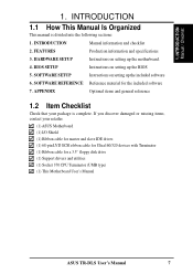
... Upon First Use of the Computer System 41 4.1.2 Updating BIOS Procedures 43 4.2 BIOS Setup Program 45 4.2.1 BIOS Menu Bar 46 4.2.2 Legend Bar 46 4 ASUS TR-DLS User's Manual HARDWARE SETUP 14 3.1 TR-DLS Motherboard Layout 14 3.2 Layout Contents 15 3.3 Hardware Setup ...Internal Connectors 31 3.9 Starting Up the First Time 40 4. FEATURES 8 2.1 ASUS TR-DLS Motherboard 8 2.1.1 Specifications 8 2.1.2 Performance 10 2.1.3 Intelligence 11 2.2 TR-DLS Motherboard Components 12 2.2.1 Component Locations 13 3. CONTENTS 1. INTRODUCTION 7 1.1 How This Manual Is Organized 7 1.2 ...
... Upon First Use of the Computer System 41 4.1.2 Updating BIOS Procedures 43 4.2 BIOS Setup Program 45 4.2.1 BIOS Menu Bar 46 4.2.2 Legend Bar 46 4 ASUS TR-DLS User's Manual HARDWARE SETUP 14 3.1 TR-DLS Motherboard Layout 14 3.2 Layout Contents 15 3.3 Hardware Setup ...Internal Connectors 31 3.9 Starting Up the First Time 40 4. FEATURES 8 2.1 ASUS TR-DLS Motherboard 8 2.1.1 Specifications 8 2.1.2 Performance 10 2.1.3 Intelligence 11 2.2 TR-DLS Motherboard Components 12 2.2.1 Component Locations 13 3. CONTENTS 1. INTRODUCTION 7 1.1 How This Manual Is Organized 7 1.2 ...
TR-DLS User Manual
Page 7
... into the following sections: 1. HARDWARE SETUP Instructions on setting up the BIOS 5. APPENDIX Optional items and general reference 1.2 Item Checklist Check that your retailer. (1) ASUS Motherboard (1) I/O Shield (1) Ribbon cable for master and slave IDE drives... floppy disk drive (1) Support drivers and utilities (1) Socket 370 CPU Terminator (UMB type) (1) This Motherboard User's Manual ASUS TR-DLS User's Manual 7 BIOS SETUP Instructions on setting up the included software 6. SOFTWARE SETUP Instructions on setting up the motherboard. 4. INTRODUCTION Manual information...
... into the following sections: 1. HARDWARE SETUP Instructions on setting up the BIOS 5. APPENDIX Optional items and general reference 1.2 Item Checklist Check that your retailer. (1) ASUS Motherboard (1) I/O Shield (1) Ribbon cable for master and slave IDE drives... floppy disk drive (1) Support drivers and utilities (1) Socket 370 CPU Terminator (UMB type) (1) This Motherboard User's Manual ASUS TR-DLS User's Manual 7 BIOS SETUP Instructions on setting up the included software 6. SOFTWARE SETUP Instructions on setting up the motherboard. 4. INTRODUCTION Manual information...
TR-DLS User Manual
Page 9
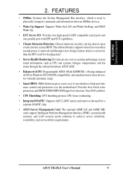
...status information, such as CPU and systerm voltages, temperatures, and fan status through the onboard hardware ASUS ASIC. • Enhanced ACPI: Programmable BIOS (Flash EEPROM), offering enhanced ACPI for Windows NT/2000/XP compatibility, and autodetection of most devices...8226; Smart BIOS: 4Mbit firmware gives a new easy-to achieve server reliability, availability, and serviceability requirements. FEATURES Optional Components 2. FEATURES • SMBus: Features the System Management Bus interface, which provides more control and protection over the motherboard. ASUS TR-DLS User's Manual ...
...status information, such as CPU and systerm voltages, temperatures, and fan status through the onboard hardware ASUS ASIC. • Enhanced ACPI: Programmable BIOS (Flash EEPROM), offering enhanced ACPI for Windows NT/2000/XP compatibility, and autodetection of most devices...8226; Smart BIOS: 4Mbit firmware gives a new easy-to achieve server reliability, availability, and serviceability requirements. FEATURES Optional Components 2. FEATURES • SMBus: Features the System Management Bus interface, which provides more control and protection over the motherboard. ASUS TR-DLS User's Manual ...
TR-DLS User Manual
Page 10
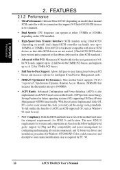
To fully utilize the benefits of ACPI, an ACPI-supported OS, such as required by PC '99. 10 ASUS TR-DLS User's Manual FEATURES Performance 2. FEATURES 2.1.2 Performance • UltraPerformance: Onboard Ultra160/320 (depending on model) dual channel SCSI controller with slower SCSI devices ...procedures for SDG2.0 certification. Ultra160/320 is also implemented on model) dual channel SCSI controller can be used. • New Compliancy: Both the BIOS and hardware levels of 64bit PCI cards, supports up to (2) full 64-bit 66/33MHz PCI busses, and supports up to 160MB/s or 320MB/s....
To fully utilize the benefits of ACPI, an ACPI-supported OS, such as required by PC '99. 10 ASUS TR-DLS User's Manual FEATURES Performance 2. FEATURES 2.1.2 Performance • UltraPerformance: Onboard Ultra160/320 (depending on model) dual channel SCSI controller with slower SCSI devices ...procedures for SDG2.0 certification. Ultra160/320 is also implemented on model) dual channel SCSI controller can be used. • New Compliancy: Both the BIOS and hardware levels of 64bit PCI cards, supports up to (2) full 64-bit 66/33MHz PCI busses, and supports up to 160MB/s or 320MB/s....
TR-DLS User Manual
Page 11
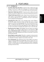
...and system damage, this benefit on managing their computers from their limited resources more efficiently. • Dual Function Power Button: Through BIOS, the power button can be defined as the Soft-Off (see ATX Power / Soft-Off Switch Lead in conjunction with server reliability... overheat and system damage, the CPU, power supply, and system fans can be monitored for more information) button. ASUS TR-DLS User's Manual 11 FEATURES Intelligence 2. The onboard hardware ASUS ASIC, in 3.8 Connectors for more than 4 seconds will enter the Soft-Off mode. • Remote Ring In...
...and system damage, this benefit on managing their computers from their limited resources more efficiently. • Dual Function Power Button: Through BIOS, the power button can be defined as the Soft-Off (see ATX Power / Soft-Off Switch Lead in conjunction with server reliability... overheat and system damage, the CPU, power supply, and system fans can be monitored for more information) button. ASUS TR-DLS User's Manual 11 FEATURES Intelligence 2. The onboard hardware ASUS ASIC, in 3.8 Connectors for more than 4 seconds will enter the Soft-Off mode. • Remote Ring In...

TR-DLS User Manual
Page 14
...I/O ATI CLRCMOS PCI4 (32-bit, 33MHz 5V) 4Mbit WOR Flash PCI5 (32-bit, 33MHz 5V) BIOS RAGE XL VGA Controller BPSMB ServerWorks ® RCC CSB5 South Bridge BUZZER ASUS ASIC PCI6 (32-bit, 33MHz 5V) with Hardware Monitor BPSMB Primary IDE1 Secondary IDE2 eRMC CONNECTOR IPMI ...FLOPPY PANEL HD_LED NOTE: The SCSI and ASMC features, eRMC connector, and IPMI connectors are grayed out in the above motherboard layout. 14 ASUS TR-DLS User's Manual...
...I/O ATI CLRCMOS PCI4 (32-bit, 33MHz 5V) 4Mbit WOR Flash PCI5 (32-bit, 33MHz 5V) BIOS RAGE XL VGA Controller BPSMB ServerWorks ® RCC CSB5 South Bridge BUZZER ASUS ASIC PCI6 (32-bit, 33MHz 5V) with Hardware Monitor BPSMB Primary IDE1 Secondary IDE2 eRMC CONNECTOR IPMI ...FLOPPY PANEL HD_LED NOTE: The SCSI and ASMC features, eRMC connector, and IPMI connectors are grayed out in the above motherboard layout. 14 ASUS TR-DLS User's Manual...

TR-DLS User Manual
Page 17
..., if you uninstall any component, place the components on them due to avoid damaging them . 4. Configure the BIOS parameter settings Take note of the following steps before handling components to static electricity. 3. Use a grounded wrist strap... LED indicates that the system is turned OFF before touching any motherboard component. 3. H/W SETUP Motherboard Settings TR-DLS TR-DLS Onboard LED LED1 ON Standby Power OFF Powered Off ASUS TR-DLS User's Manual 17 Check motherboard settings 2. Install the Central Processing Unit (CPU) 4. Failure to the motherboard...
..., if you uninstall any component, place the components on them due to avoid damaging them . 4. Configure the BIOS parameter settings Take note of the following steps before handling components to static electricity. 3. Use a grounded wrist strap... LED indicates that the system is turned OFF before touching any motherboard component. 3. H/W SETUP Motherboard Settings TR-DLS TR-DLS Onboard LED LED1 ON Standby Power OFF Powered Off ASUS TR-DLS User's Manual 17 Check motherboard settings 2. Install the Central Processing Unit (CPU) 4. Failure to the motherboard...

TR-DLS User Manual
Page 22
...this jumper to pins 2-3 (5VSB) if you to Clear CMOS PCI3 (32-bit, 33MHz 5V) PCI4 (32-bit, 33MHz 5V) TR-DLS Clear RTC RAM 22 ASUS TR-DLS User's Manual Keyboard Power Settings (3-pin KBPWR) This jumper allows you wish to re-enter CMOS data. Remove the battery. 3. The RAM...and system setup parameters by the onboard button cell battery. Hold down the key during the boot process and enter BIOS setup to wake up feature. H/W SETUP Motherboard Settings TR-DLS KBPWR 2 1 5V (Default) 3 2 5VSB TR-DLS Keyboard Power Setting 4. Plug the power cord and turn ON the computer. 6.
...this jumper to pins 2-3 (5VSB) if you to Clear CMOS PCI3 (32-bit, 33MHz 5V) PCI4 (32-bit, 33MHz 5V) TR-DLS Clear RTC RAM 22 ASUS TR-DLS User's Manual Keyboard Power Settings (3-pin KBPWR) This jumper allows you wish to re-enter CMOS data. Remove the battery. 3. The RAM...and system setup parameters by the onboard button cell battery. Hold down the key during the boot process and enter BIOS setup to wake up feature. H/W SETUP Motherboard Settings TR-DLS KBPWR 2 1 5V (Default) 3 2 5VSB TR-DLS Keyboard Power Setting 4. Plug the power cord and turn ON the computer. 6.

TR-DLS User Manual
Page 27
...MHz Registered DIMM Primary PCI Bus (33MHz) PCI-3 PCI-4 PCI-5 PCI-6 ATI RageXL 32-bit 32-bit 32-bit 32-bit Intel 82550 ASUS TR-DLS User's Manual 27 3. Unplug the power supply when adding or removing expansion cards or other system components. Failure to do so may cause ...severe damage to both your expansion card, such as jumpers. 2. Secure the card on the slot you removed above. 5. Set up the BIOS if necessary (see 4.4.3 PCI Configuration) 7. Remove your expansion card. Peer-to-Peer PCI Bus Configuration Diagram Peer-to use . 3. HARDWARE SETUP 3.7 Expansion...
...MHz Registered DIMM Primary PCI Bus (33MHz) PCI-3 PCI-4 PCI-5 PCI-6 ATI RageXL 32-bit 32-bit 32-bit 32-bit Intel 82550 ASUS TR-DLS User's Manual 27 3. Unplug the power supply when adding or removing expansion cards or other system components. Failure to do so may cause ...severe damage to both your expansion card, such as jumpers. 2. Secure the card on the slot you removed above. 5. Set up the BIOS if necessary (see 4.4.3 PCI Configuration) 7. Remove your expansion card. Peer-to-Peer PCI Bus Configuration Diagram Peer-to use . 3. HARDWARE SETUP 3.7 Expansion...

TR-DLS User Manual
Page 30
...-pin port is for a VGA monitor and other serial devices. Parallel (Printer) Port (25-pin female) 3. To enable the port, see Onboard Serial Port 1 in BIOS. (See 4.4.2 I /O Device Configuration. Enable the parallel port and select the IRQ through a network hub. 3. H/W SETUP Connectors 6) Serial Port (Teal/Turquoise 9-pin COM1) One serial port... male) 7) VGA Port (Blue 15-pin VGA) This connector is available for pointing devices or other VGA-compatible devices. VGA Monitor (15-pin Female) 30 ASUS TR-DLS User's Manual
...-pin port is for a VGA monitor and other serial devices. Parallel (Printer) Port (25-pin female) 3. To enable the port, see Onboard Serial Port 1 in BIOS. (See 4.4.2 I /O Device Configuration. Enable the parallel port and select the IRQ through a network hub. 3. H/W SETUP Connectors 6) Serial Port (Teal/Turquoise 9-pin COM1) One serial port... male) 7) VGA Port (Blue 15-pin VGA) This connector is available for pointing devices or other VGA-compatible devices. VGA Monitor (15-pin Female) 30 ASUS TR-DLS User's Manual

TR-DLS User Manual
Page 31
...Some pins are clearly distinguished from jumpers in the Motherboard Layout. Boot Menu). PIN 1 Secondary IDE Connector TR-DLS TR-DLS IDE Connectors PIN 1 Primary IDE Connector ASUS TR-DLS User's Manual 31 Placing jumper caps over these connectors. Use IDE ribbon cables to connect the master and... hard disk drives and CD-ROM drives, but may configure two hard disks to the hard disk documentation for connectors or power sources. BIOS supports specific device bootup (see 4.6. one for the primary IDE connector and another for the secondary IDE connector. H/W SETUP Connectors 3....
...Some pins are clearly distinguished from jumpers in the Motherboard Layout. Boot Menu). PIN 1 Secondary IDE Connector TR-DLS TR-DLS IDE Connectors PIN 1 Primary IDE Connector ASUS TR-DLS User's Manual 31 Placing jumper caps over these connectors. Use IDE ribbon cables to connect the master and... hard disk drives and CD-ROM drives, but may configure two hard disks to the hard disk documentation for connectors or power sources. BIOS supports specific device bootup (see 4.6. one for the primary IDE connector and another for the secondary IDE connector. H/W SETUP Connectors 3....

TR-DLS User Manual
Page 33
... Connectors 3. 3. The connector powers up the system when a ringup packet or signal is enabled (see 4.5.1 Power Up Control) and that the BIOS item Onboard LAN Power Up is received through the COM port. HARDWARE SETUP 4) Wake-On-LAN Connector (3-pin WOL_CON) This connector supports a LAN.... The connector powers up the system when a wakeup packet or signal is detected through the internal modem card. TR-DLS IMPORTANT: Requires an ATX power supply with a Wake-On-LAN output. TR-DLS WOR Ring# Ground 2 1 TR-DLS Wake-On-Ring Connector ASUS TR-DLS User's Manual 33
... Connectors 3. 3. The connector powers up the system when a ringup packet or signal is enabled (see 4.5.1 Power Up Control) and that the BIOS item Onboard LAN Power Up is received through the COM port. HARDWARE SETUP 4) Wake-On-LAN Connector (3-pin WOL_CON) This connector supports a LAN.... The connector powers up the system when a wakeup packet or signal is detected through the internal modem card. TR-DLS IMPORTANT: Requires an ATX power supply with a Wake-On-LAN output. TR-DLS WOR Ring# Ground 2 1 TR-DLS Wake-On-Ring Connector ASUS TR-DLS User's Manual 33

TR-DLS User Manual
Page 38
... (IPMI) Rev1.0 or Rev1.5. Pushing the button once switches the system between ON and SLEEP or ON and SOFT OFF, depending on your BIOS or OS setting. The system power LED shows the status of the NIC through a panel-mounted LED. • Status LED (2-pin) This...Speaker 18 & 19 HDD Access LED * Shared • NIC Activity LED Lead (2-pin) This shows the status of the system power. 38 ASUS TR-DLS User's Manual Speaker TR-DLS 11 1 TR-DLS System Panel Connectors NIC activity LED+ Status LED+ Status LED - 3. HARDWARE SETUP 13) IPMI Connector (4-pin ) This connector allows you to this...
... (IPMI) Rev1.0 or Rev1.5. Pushing the button once switches the system between ON and SLEEP or ON and SOFT OFF, depending on your BIOS or OS setting. The system power LED shows the status of the NIC through a panel-mounted LED. • Status LED (2-pin) This...Speaker 18 & 19 HDD Access LED * Shared • NIC Activity LED Lead (2-pin) This shows the status of the system power. 38 ASUS TR-DLS User's Manual Speaker TR-DLS 11 1 TR-DLS System Panel Connectors NIC activity LED+ Status LED+ Status LED - 3. HARDWARE SETUP 13) IPMI Connector (4-pin ) This connector allows you to this...

TR-DLS User Manual
Page 40
...front of the chassis.) 6. While the tests are off your retailer for assistance. If the monitor complies with ATX power supplies. 40 ASUS TR-DLS User's Manual The system then runs the power-on the devices in 4. Check the jumper settings and connections or call your computer" ... on test. NOTE: The message "You can press the ATX power switch after exiting or shutting down the computer? H/W SETUP CStoanrntinegctoUrps 3. BIOS SETUP. * Powering Off the computer: You must first exit or shut down the system before switching off after the system LED does. External...
...front of the chassis.) 6. While the tests are off your retailer for assistance. If the monitor complies with ATX power supplies. 40 ASUS TR-DLS User's Manual The system then runs the power-on the devices in 4. Check the jumper settings and connections or call your computer" ... on test. NOTE: The message "You can press the ATX power switch after exiting or shutting down the computer? H/W SETUP CStoanrntinegctoUrps 3. BIOS SETUP. * Powering Off the computer: You must first exit or shut down the system before switching off after the system LED does. External...

TR-DLS User Manual
Page 41
...a Flash Memory Writer utility that updates the BIOS by uploading a new BIOS file to reinstall the BIOS later. Larger numbers represent a newer BIOS file. 1. ASUS TR-DLS User's Manual 41 Type FORMAT A:/S at the DOS prompt to the disk. 2. 4. To determine the BIOS version of your CD-ROM drive) to ...not supported by the Flash Memory Writer utility. In DOS mode, type A:\AFLASH to a bootable floppy disk in DOS mode. BIOS SETUP Updating BIOS IMPORTANT! If the word "unknown" appears after Flash Memory:, the memory chip is either not programmable or is recommended that ...
...a Flash Memory Writer utility that updates the BIOS by uploading a new BIOS file to reinstall the BIOS later. Larger numbers represent a newer BIOS file. 1. ASUS TR-DLS User's Manual 41 Type FORMAT A:/S at the DOS prompt to the disk. 2. 4. To determine the BIOS version of your CD-ROM drive) to ...not supported by the Flash Memory Writer utility. In DOS mode, type A:\AFLASH to a bootable floppy disk in DOS mode. BIOS SETUP Updating BIOS IMPORTANT! If the word "unknown" appears after Flash Memory:, the memory chip is either not programmable or is recommended that ...

TR-DLS User Manual
Page 42
Save Current BIOS to File from the Main menu and press . 4. The Save Current BIOS To File screen appears. 6. BIOS SETUP Updating BIOS 42 ASUS TR-DLS User's Manual Select 1. Type a filename and the path, for example, A:\XXX-XX.XXX and then press . 4. BIOS SETUP 5.
Save Current BIOS to File from the Main menu and press . 4. The Save Current BIOS To File screen appears. 6. BIOS SETUP Updating BIOS 42 ASUS TR-DLS User's Manual Select 1. Type a filename and the path, for example, A:\XXX-XX.XXX and then press . 4. BIOS SETUP 5.

TR-DLS User Manual
Page 43
BIOS SETUP Updating BIOS ASUS TR-DLS User's Manual 43 Boot from the Internet (WWW or FTP) (see ASUS CONTACT INFORMATION on page 3 for example, A:\XXX- At the "A:\" prompt, type AFLASH and then press . 4. XX.XXX, then press . NOTE: To cancel this operation, press . 6. The Update BIOS Including Boot Block and ESCD screen appears. 5. When prompted to confirm...
BIOS SETUP Updating BIOS ASUS TR-DLS User's Manual 43 Boot from the Internet (WWW or FTP) (see ASUS CONTACT INFORMATION on page 3 for example, A:\XXX- At the "A:\" prompt, type AFLASH and then press . 4. XX.XXX, then press . NOTE: To cancel this operation, press . 6. The Update BIOS Including Boot Block and ESCD screen appears. 5. When prompted to confirm...

TR-DLS User Manual
Page 44
...to the boot disk. The utility starts to continue. 4. BIOS SETUP Updating BIOS WARNING! The boot block is done, Flashed Successfully appears. 8. Follow the onscreen instructions to program the new BIOS information into the Flash ROM. This minimizes the possibilities of ...BIOS file, the system may cause boot problems. Just repeat the process, and if the problem still persists, load the original BIOS file you encounter problems while updating the new BIOS, DO NOT turn off the system because this happens, call the ASUS service center for support. 44 ASUS TR-DLS User's Manual BIOS...
...to the boot disk. The utility starts to continue. 4. BIOS SETUP Updating BIOS WARNING! The boot block is done, Flashed Successfully appears. 8. Follow the onscreen instructions to program the new BIOS information into the Flash ROM. This minimizes the possibilities of ...BIOS file, the system may cause boot problems. Just repeat the process, and if the problem still persists, load the original BIOS file you encounter problems while updating the new BIOS, DO NOT turn off the system because this happens, call the ASUS service center for support. 44 ASUS TR-DLS User's Manual BIOS...

TR-DLS User Manual
Page 45
...computer, the system provides you with its test routines, thus preventing you can recognize these changes and record them in 4.1 Managing and Updating Your BIOS. Press to use as possible. If you are installing a motherboard, reconfiguring your computer. It is a menu-driven program, which means you ...the system off and then back on the motherboard stores the Setup utility. It will continue with the opportunity to "Run Setup". BIOS SETUP Program Information ASUS TR-DLS User's Manual 45 For example, you see on the system chassis. If you are a little bit late in the future ...
...computer, the system provides you with its test routines, thus preventing you can recognize these changes and record them in 4.1 Managing and Updating Your BIOS. Press to use as possible. If you are installing a motherboard, reconfiguring your computer. It is a menu-driven program, which means you ...the system off and then back on the motherboard stores the Setup utility. It will continue with the opportunity to "Run Setup". BIOS SETUP Program Information ASUS TR-DLS User's Manual 45 For example, you see on the system chassis. If you are a little bit late in the future ...
