T2-R User Manual
Page 8
... This chapter gives information about the motherboard that comes with hardware knowledge of the ASUS Terminator 2. Chapter 2: Basic installation This chapter provides step-by-step instructions on Deluxe-Commercial models only). 8 Appendix The Appendix includes the IEEE 802.11b channels for...This guide is organized This guide contains the following parts: 1. The chapter lists the system features, including introduction on the ASUS Terminator 2 barebone system. Safeguards About this guide Audience This guide provides general information on the front and rear panel, and internal...
... This chapter gives information about the motherboard that comes with hardware knowledge of the ASUS Terminator 2. Chapter 2: Basic installation This chapter provides step-by-step instructions on Deluxe-Commercial models only). 8 Appendix The Appendix includes the IEEE 802.11b channels for...This guide is organized This guide contains the following parts: 1. The chapter lists the system features, including introduction on the ASUS Terminator 2 barebone system. Safeguards About this guide Audience This guide provides general information on the front and rear panel, and internal...
T2-R User Manual
Page 10
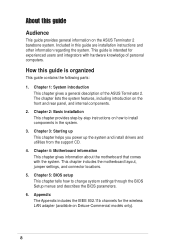
... panel • CPU fan and heatsink assembly 2. System package contents Check your Terminator 2 system package for the following items. If any of the items is damaged or missing, contact your retailer immediately. Support CD 4. Item Description T2-R Models Commercial Deluxe Deluxe Standard 1. ASUS Terminator 2 barebone system with dipolar antenna), and Gigabit LAN ** CD-ROM/CD-RW...
... panel • CPU fan and heatsink assembly 2. System package contents Check your Terminator 2 system package for the following items. If any of the items is damaged or missing, contact your retailer immediately. Support CD 4. Item Description T2-R Models Commercial Deluxe Deluxe Standard 1. ASUS Terminator 2 barebone system with dipolar antenna), and Gigabit LAN ** CD-ROM/CD-RW...
T2-R User Manual
Page 11
MODE ASUS Terminator 2 barebone system The chapter lists the system features, including introduction on the front and rear panel, and internal components. System introduction Chapter 1 This chapter gives a general description of the ASUS Terminator 2.
MODE ASUS Terminator 2 barebone system The chapter lists the system features, including introduction on the front and rear panel, and internal components. System introduction Chapter 1 This chapter gives a general description of the ASUS Terminator 2.
T2-R User Manual
Page 12
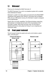
... features of the many more, the Terminator 2 definitely delivers the cutting edge technology for choosing the ASUS Terminator 2! Superb video and audio capabilities, Fast Ethernet/wireless networking, and extensive connectivity are just some of the Terminator 2 system. Thank you for your ..., system LEDs, and LED panel. Delivered in -one barebone system with an 800MHz FSB, and up to 2GB system memory, the Terminator 2 system is designed for the sophisticated. 1.1 Welcome! Commercial Deluxe & Deluxe model Standard model 1 2 1 2 3 4 9 10 MODE 5 6 7 8 11 12 13 14 MODE 3 4 5 ...
... features of the many more, the Terminator 2 definitely delivers the cutting edge technology for choosing the ASUS Terminator 2! Superb video and audio capabilities, Fast Ethernet/wireless networking, and extensive connectivity are just some of the Terminator 2 system. Thank you for your ..., system LEDs, and LED panel. Delivered in -one barebone system with an 800MHz FSB, and up to 2GB system memory, the Terminator 2 system is designed for the sophisticated. 1.1 Welcome! Commercial Deluxe & Deluxe model Standard model 1 2 1 2 3 4 9 10 MODE 5 6 7 8 11 12 13 14 MODE 3 4 5 ...
T2-R User Manual
Page 13
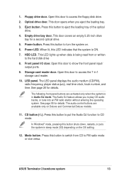
... up when data is ON. 7. See page 20 for a second optical drive. 5. The following front panel buttons are available only on Deluxe and Commercial Deluxe models. 11. Floppy drive door. HDD LED. Open this button to put the Audio DJ function to show the front panel input/ output... ports. 9. LED panel. The Audio DJ feature allows you eject the loading tray. 3. Press this door to CD mode. ASUS Terminator 2 barebone system 13...
... up when data is ON. 7. See page 20 for a second optical drive. 5. The following front panel buttons are available only on Deluxe and Commercial Deluxe models. 11. Floppy drive door. HDD LED. Open this button to put the Audio DJ function to show the front panel input/ output... ports. 9. LED panel. The Audio DJ feature allows you eject the loading tray. 3. Press this door to CD mode. ASUS Terminator 2 barebone system 13...
T2-R User Manual
Page 15
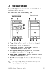
... IDE optical drive. 21. This drive is for a Memory Stick®/Memory Stick Pro™ storage card. 23. ASUS Terminator 2 barebone system 15 Open the front panel doors by pressing the mark. Commercial Deluxe and Deluxe model 19 20 Standard model 19 20 21 22 23 24 MODE 25 26 27 28 29 30...
... IDE optical drive. 21. This drive is for a Memory Stick®/Memory Stick Pro™ storage card. 23. ASUS Terminator 2 barebone system 15 Open the front panel doors by pressing the mark. Commercial Deluxe and Deluxe model 19 20 Standard model 19 20 21 22 23 24 MODE 25 26 27 28 29 30...
T2-R User Manual
Page 17
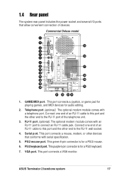
... port (optional). Serial port. This green 6-pin connector is for a PS/2 mouse. 6. This port connects a VGA monitor. Connect one end of devices. ASUS Terminator 2 barebone system 17 Telephone port (optional). Commercial Deluxe model 1 2 15 3 4 5 16 6 7 8 17 9 10 18 11 12 19 13 14 20 21 22 23 24 1. The optional modem module comes...
... port (optional). Serial port. This green 6-pin connector is for a PS/2 mouse. 6. This port connects a VGA monitor. Connect one end of devices. ASUS Terminator 2 barebone system 17 Telephone port (optional). Commercial Deluxe model 1 2 15 3 4 5 16 6 7 8 17 9 10 18 11 12 19 13 14 20 21 22 23 24 1. The optional modem module comes...
T2-R User Manual
Page 19
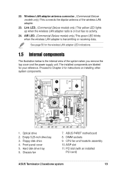
... to Chapter 2 for instructions on but has no activity. 24. Empty 5.25-inch drive bay 3. DIMM sockets 9. Chassis fan 7. AIR LED. (Commercial Deluxe models only.) This green LED blinks when the wireless LAN adapter is on installing other system components. 1 6 3 2 9 10 11 8 7 4 ...internal view of the wireless LAN adapter. 23. ASUS P4R8T motherboard 8. PCI slot (with an installed PCI card) ASUS Terminator 2 barebone system 19 22. Hard disk drive tray 6. Wireless LAN adapter antenna connector. (Commercial Deluxe models only.) This connects the dipolar antenna of ...
... to Chapter 2 for instructions on but has no activity. 24. Empty 5.25-inch drive bay 3. DIMM sockets 9. Chassis fan 7. AIR LED. (Commercial Deluxe models only.) This green LED blinks when the wireless LAN adapter is on installing other system components. 1 6 3 2 9 10 11 8 7 4 ...internal view of the wireless LAN adapter. 23. ASUS P4R8T motherboard 8. PCI slot (with an installed PCI card) ASUS Terminator 2 barebone system 19 22. Hard disk drive tray 6. Wireless LAN adapter antenna connector. (Commercial Deluxe models only.) This connects the dipolar antenna of ...
T2-R User Manual
Page 21
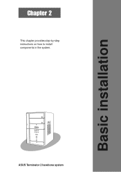
Basic installation Chapter 2 This chapter provides step-by-step instructions on how to install components in the system. MODE ASUS Terminator 2 barebone system
Basic installation Chapter 2 This chapter provides step-by-step instructions on how to install components in the system. MODE ASUS Terminator 2 barebone system
T2-R User Manual
Page 23
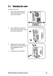
Use a Phillips screw driver to the chassis. 1 1 2. Keep the screws for later use. 2 3. Lift the cover, then set aside. 2 2 4 3 3 ASUS Terminator 2 barebone system 23 2.3 Removing the cover To remove the cover: 1. On the rear panel, locate the three screws that secure the 1 cover to remove the cover screws. Slightly pull the cover toward the rear panel until the side tabs are disengaged from the chassis. 4.
Use a Phillips screw driver to the chassis. 1 1 2. Keep the screws for later use. 2 3. Lift the cover, then set aside. 2 2 4 3 3 ASUS Terminator 2 barebone system 23 2.3 Removing the cover To remove the cover: 1. On the rear panel, locate the three screws that secure the 1 cover to remove the cover screws. Slightly pull the cover toward the rear panel until the side tabs are disengaged from the chassis. 4.
T2-R User Manual
Page 25
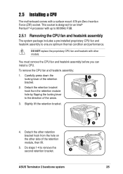
... can install a CPU. Detach the other retention bracket hook from the retention module hole by flipping the locking lever 2 to remove the second retention bracket. 4 ASUS Terminator 2 barebone system 3 25 DO NOT replace the proprietary CPU fan and heatsink with other side of the retention module, then lift. 5. Detach the retention bracket...
... can install a CPU. Detach the other retention bracket hook from the retention module hole by flipping the locking lever 2 to remove the second retention bracket. 4 ASUS Terminator 2 barebone system 3 25 DO NOT replace the proprietary CPU fan and heatsink with other side of the retention module, then lift. 5. Detach the retention bracket...
T2-R User Manual
Page 27
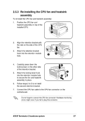
... retention bracket. 5. Carefully press down the locking lever on the side of the installed CPU. 1 2. Do not forget to re-install the second retention bracket. 7. ASUS Terminator 2 barebone system 27 Attach the retention bracket hook into the retention module hole to plug this connector. 2.5.3 Re-installing the CPU fan and heatsink assembly...
... retention bracket. 5. Carefully press down the locking lever on the side of the installed CPU. 1 2. Do not forget to re-install the second retention bracket. 7. ASUS Terminator 2 barebone system 27 Attach the retention bracket hook into the retention module hole to plug this connector. 2.5.3 Re-installing the CPU fan and heatsink assembly...
T2-R User Manual
Page 29
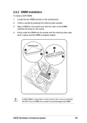
Unlock a socket by pressing the retaining clips outward. 3. Firmly insert the DIMM into a socket to avoid damaging the DIMM! ASUS Terminator 2 barebone system 29 Align a DIMM on the socket such that it fits in place and the DIMM is properly seated. DO NOT force a DIMM into the socket until the retaining clips snap back in only one direction. 2.6.2 DIMM installation To install a DDR DIMM. 1. Locate the two DIMM sockets on the socket. 4. Retaining clips 3 2 4 2 4 1 A DDR DIMM is keyed with a notch so that the notch on the DIMM matches the break on the motherboard. 2.
Unlock a socket by pressing the retaining clips outward. 3. Firmly insert the DIMM into a socket to avoid damaging the DIMM! ASUS Terminator 2 barebone system 29 Align a DIMM on the socket such that it fits in place and the DIMM is properly seated. DO NOT force a DIMM into the socket until the retaining clips snap back in only one direction. 2.6.2 DIMM installation To install a DDR DIMM. 1. Locate the two DIMM sockets on the socket. 4. Retaining clips 3 2 4 2 4 1 A DDR DIMM is keyed with a notch so that the notch on the DIMM matches the break on the motherboard. 2.
T2-R User Manual
Page 31
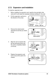
... the card to the direction of the arrow. 2 Expansion card lock PCI slot AGP slot 3. Pull the expansion card lock to the chassis. 4 PCI card 5 ASUS Terminator 2 barebone system 31 Before installing the expansion card, read the documentation that you intend to use. Remove the metal bracket 3 opposite the slot that came...
... the card to the direction of the arrow. 2 Expansion card lock PCI slot AGP slot 3. Pull the expansion card lock to the chassis. 4 PCI card 5 ASUS Terminator 2 barebone system 31 Before installing the expansion card, read the documentation that you intend to use. Remove the metal bracket 3 opposite the slot that came...
T2-R User Manual
Page 33
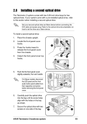
...Carefully push the optical drive into the bay until its screw holes align with two screws on one side of the bay. 6 5 7 ASUS Terminator 2 barebone system 33 Refer to the optical drive documentation on the bay as Slave device before removing the front panel cover. 6. Place the... chassis upright. 2. To install a second optical drive: 1. On Deluxe models, disconnect the LED panel and the front audio button panel cables from the chassis. 4. Locate the front panel cover hooks. 3. 2.8 Installing a...
...Carefully push the optical drive into the bay until its screw holes align with two screws on one side of the bay. 6 5 7 ASUS Terminator 2 barebone system 33 Refer to the optical drive documentation on the bay as Slave device before removing the front panel cover. 6. Place the... chassis upright. 2. To install a second optical drive: 1. On Deluxe models, disconnect the LED panel and the front audio button panel cables from the chassis. 4. Locate the front panel cover hooks. 3. 2.8 Installing a...
T2-R User Manual
Page 35
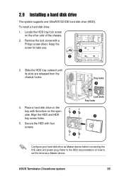
... 5 4 5 Configure your hard disk drive as a Master device. Refer to the HDD documentation on the tray with its slots are released from the chassis hooks. ASUS Terminator 2 barebone system 35 Keep the screw for later use. 1 2 3. To install a hard disk drive: 1. Locate the HDD tray lock screw on the open side. Slide...
... 5 4 5 Configure your hard disk drive as a Master device. Refer to the HDD documentation on the tray with its slots are released from the chassis hooks. ASUS Terminator 2 barebone system 35 Keep the screw for later use. 1 2 3. To install a hard disk drive: 1. Locate the HDD tray lock screw on the open side. Slide...
T2-R User Manual
Page 37
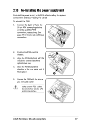
... the cables. See page 77 for the location of these 1 connectors. 1 2. To reinstall the PSU: 1. Secure the PSU with the CPU and/or chassis fans. 5 ASUS Terminator 2 barebone system 37 Connect the 4-pin 12V and the 20-pin ATX power plugs to the ATX12V and ATXPWR connectors, respectively.
... the cables. See page 77 for the location of these 1 connectors. 1 2. To reinstall the PSU: 1. Secure the PSU with the CPU and/or chassis fans. 5 ASUS Terminator 2 barebone system 37 Connect the 4-pin 12V and the 20-pin ATX power plugs to the ATX12V and ATXPWR connectors, respectively.
T2-R User Manual
Page 39
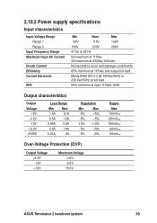
... Max -5% +5% -5% +5% -10% +10% -5% +5% -5% +5% Ripple Max 50mVp-p 120mVp-p 150mVp-p 60mVp-p 60mVp-p Over-Voltage Protection (OVP) Output Voltage +3.3V +5V +12V Maximum Voltage 4.6V 6.5V 15.6V ASUS Terminator 2 barebone system 39
... Max -5% +5% -5% +5% -10% +10% -5% +5% -5% +5% Ripple Max 50mVp-p 120mVp-p 150mVp-p 60mVp-p 60mVp-p Over-Voltage Protection (OVP) Output Voltage +3.3V +5V +12V Maximum Voltage 4.6V 6.5V 15.6V ASUS Terminator 2 barebone system 39
T2-R User Manual
Page 41
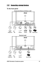
2.12 Connecting external devices To the front panel Commercial Deluxe and Deluxe model Headphone Mic Scanner Camera Standard model HDD Audio Devices Headphone Mic Scanner Audio Devices ASUS Terminator 2 barebone system 41
2.12 Connecting external devices To the front panel Commercial Deluxe and Deluxe model Headphone Mic Scanner Camera Standard model HDD Audio Devices Headphone Mic Scanner Audio Devices ASUS Terminator 2 barebone system 41
T2-R User Manual
Page 43
MODE ASUS Terminator 2 barebone system Starting up Chapter 3 This chapter helps you power up the system and install drivers and utilities from the support CD.
MODE ASUS Terminator 2 barebone system Starting up Chapter 3 This chapter helps you power up the system and install drivers and utilities from the support CD.