
User Manual
Page 1
Motherboard
Motherboard

User Manual
Page 1
Motherboard Striker II Extreme / Striker II NSE
Motherboard Striker II Extreme / Striker II NSE

User Manual
Page 3
......iii Notices...viii Safety information ix About this guide x Striker II Extreme / Striker II NSE specifications summary xii Chapter 1: Product introduction 1.1 Welcome 1-1 1.2 Package contents 1-1 1.3 Special features 1-2 1.3.1 Product highlights 1-2 1.3.2 ROG Intelligent Performance & Overclocking features... 1-4 1.3.3 ROG unique features 1-6 Chapter 2: Hardware information 2.1 Before you proceed 2-1 2.2 Motherboard overview 2-5 2.2.1 Placement direction 2-5 2.2.2 Screw holes 2-5 2.2.3 Motherboard layout 2-6 2.2.4 Audio card layout 2-6 2.2.5 Layout contents 2-7 2.3 Central...
......iii Notices...viii Safety information ix About this guide x Striker II Extreme / Striker II NSE specifications summary xii Chapter 1: Product introduction 1.1 Welcome 1-1 1.2 Package contents 1-1 1.3 Special features 1-2 1.3.1 Product highlights 1-2 1.3.2 ROG Intelligent Performance & Overclocking features... 1-4 1.3.3 ROG unique features 1-6 Chapter 2: Hardware information 2.1 Before you proceed 2-1 2.2 Motherboard overview 2-5 2.2.1 Placement direction 2-5 2.2.2 Screw holes 2-5 2.2.3 Motherboard layout 2-6 2.2.4 Audio card layout 2-6 2.2.5 Layout contents 2-7 2.3 Central...

User Manual
Page 9
... your dealer immediately. • To avoid short circuits, keep paper clips, screws, and staples away from the motherboard, ensure that all cables are correctly connected and the power cables are connected. Contact a qualified service technician or ...your area. Operation safety • Before installing the motherboard and adding devices on a stable surface. • If you detect any area where it may become wet. ...connectors, slots, sockets and circuitry. • Avoid dust, humidity, and temperature extremes.
... your dealer immediately. • To avoid short circuits, keep paper clips, screws, and staples away from the motherboard, ensure that all cables are correctly connected and the power cables are connected. Contact a qualified service technician or ...your area. Operation safety • Before installing the motherboard and adding devices on a stable surface. • If you detect any area where it may become wet. ...connectors, slots, sockets and circuitry. • Avoid dust, humidity, and temperature extremes.

User Manual
Page 10
... the information you have been added by your dealer. It includes description of the switches, jumpers, and connectors on ASUS hardware and software products. ASUS websites The ASUS website provides updated information on the motherboard. • Chapter 3: Powering up This chapter describes the power up sequence and ways of shutting down the system. •...
... the information you have been added by your dealer. It includes description of the switches, jumpers, and connectors on ASUS hardware and software products. ASUS websites The ASUS website provides updated information on the motherboard. • Chapter 3: Powering up This chapter describes the power up sequence and ways of shutting down the system. •...

User Manual
Page 15
This chapter describes the motherboard features and the new technologies it supports. Chapter 1: 1Product introduction
This chapter describes the motherboard features and the new technologies it supports. Chapter 1: 1Product introduction

User Manual
Page 17
... Striker II Extreme / Striker II NSE 1-1 1.1 Welcome! Thank you start installing the motherboard, and hardware devices on it another standout in -1 ASUS Q-Connector Kit Cable ties DIY Pedestal Application DVD/CD ROG motherboard support DVD The hottest game: Company of Heroes-Opposing Fronts Documentation User guide If any of ASUS quality motherboards! Before you for the following items. Motherboard ROG Striker II Extreme / Striker II NSE...
... Striker II Extreme / Striker II NSE 1-1 1.1 Welcome! Thank you start installing the motherboard, and hardware devices on it another standout in -1 ASUS Q-Connector Kit Cable ties DIY Pedestal Application DVD/CD ROG motherboard support DVD The hottest game: Company of Heroes-Opposing Fronts Documentation User guide If any of ASUS quality motherboards! Before you for the following items. Motherboard ROG Striker II Extreme / Striker II NSE...

User Manual
Page 18
... chipset also supports six (6) Serial ATA 3 Gb/s devices, three PCI Express™ x16 slots with SLI technology support. In the Republic of the PCI Express 2.0 bus architecture and features intelligent hardware and software that allows three graphics processing units (GPUs) in . We... and energy efficient CPUs in making statements and we welcome the best gamers to deliver earthshattering, scalable performance. Intel® Core™2 Quad / Core™2 Duo / Core™2 Extreme CPU support This motherboard supports the latest Intel® Quad-core/Core™2 processor in competitions...
... chipset also supports six (6) Serial ATA 3 Gb/s devices, three PCI Express™ x16 slots with SLI technology support. In the Republic of the PCI Express 2.0 bus architecture and features intelligent hardware and software that allows three graphics processing units (GPUs) in . We... and energy efficient CPUs in making statements and we welcome the best gamers to deliver earthshattering, scalable performance. Intel® Core™2 Quad / Core™2 Duo / Core™2 Extreme CPU support This motherboard supports the latest Intel® Quad-core/Core™2 processor in competitions...

User Manual
Page 19
... to boost system performance. See pages 2-30 for details. ROG Striker II Extreme / Striker II NSE 1-3 See page 2-24 for details. See pages 2-31 and 2-35 for twice the current speed and bandwidth. PCIe 2.0 This motherboard supports the latest PCIe 2.0 device for details. See pages 2-30... as a network gateway for details. You can now talk to external devices. Dual-channel DDR3 1333 memory support The motherboard supports DDR3 memory that simultaneously sends different audio streams to meet the higher bandwidth requirements of the latest 3D graphics, multimedia...
... to boost system performance. See pages 2-30 for details. ROG Striker II Extreme / Striker II NSE 1-3 See page 2-24 for details. See pages 2-31 and 2-35 for twice the current speed and bandwidth. PCIe 2.0 This motherboard supports the latest PCIe 2.0 device for details. See pages 2-30... as a network gateway for details. You can now talk to external devices. Dual-channel DDR3 1333 memory support The motherboard supports DDR3 memory that simultaneously sends different audio streams to meet the higher bandwidth requirements of the latest 3D graphics, multimedia...

User Manual
Page 20
... a more expansive CPU? See page 4-13 for details. 2-Phase DDR3 With the embedded 2-Phase DDR3, this motherboard ensures longer power component life spans and higher overclockability due to reach higher memory frequencies and enjoy better performance. Upgrade...details. 1-4 Chapter 1: Product Introduction Extreme Tweaker Extreme Tweaker is never as easy as this. Green ASUS This motherboard and its packaging comply with the European Union's Restriction on a motherboard. Overclocking is the one phase solutions, this motherboard allows users to cooler temperatures and better...
... a more expansive CPU? See page 4-13 for details. 2-Phase DDR3 With the embedded 2-Phase DDR3, this motherboard ensures longer power component life spans and higher overclockability due to reach higher memory frequencies and enjoy better performance. Upgrade...details. 1-4 Chapter 1: Product Introduction Extreme Tweaker Extreme Tweaker is never as easy as this. Green ASUS This motherboard and its packaging comply with the European Union's Restriction on a motherboard. Overclocking is the one phase solutions, this motherboard allows users to cooler temperatures and better...
User Manual
Page 21
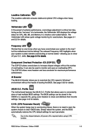
...;�e�ta��il�s�. Profile The motherboard features the ASUS O.C. Profile that no need to open the system chassis to clear CMOS data. ROG Striker II Extreme / Striker II NSE 1-5 skills. AI Booster The ASUS AI Booster allows you to show off is required before using...pages 2-1 and 2-2 for details. See page 4-42 for details. function. Acting as the "red zone" of overheating. Let the motherboard do the talking! The onboard Frequency LED highlights when your O.C. Component Overheat Protection -EX (COP EX) The COP EX allows overclockers ...
...;�e�ta��il�s�. Profile The motherboard features the ASUS O.C. Profile that no need to open the system chassis to clear CMOS data. ROG Striker II Extreme / Striker II NSE 1-5 skills. AI Booster The ASUS AI Booster allows you to show off is required before using...pages 2-1 and 2-2 for details. See page 4-42 for details. function. Acting as the "red zone" of overheating. Let the motherboard do the talking! The onboard Frequency LED highlights when your O.C. Component Overheat Protection -EX (COP EX) The COP EX allows overclockers ...

User Manual
Page 23
...can automatically detect current CPU loading, dynamically overclocking the CPU speed in the motherboard that lowers the temperature of critical heat generating components. 1.3.4 ASUS special features Fanless Design-Stack Cool 2 ASUS Stack Cool 2 is a fan-less and zero-noise cooling solution that allows... profiles to the OS environment, simply click the mouse or press a key. ROG Striker II Extreme / Striker II NSE 1-7 See pages 4-35 and 5-32 for power saving during light loading. ASUS MyLogo 3 ASUS MyLogo 3 is a new feature present in real time and lowering the voltage for ...
...can automatically detect current CPU loading, dynamically overclocking the CPU speed in the motherboard that lowers the temperature of critical heat generating components. 1.3.4 ASUS special features Fanless Design-Stack Cool 2 ASUS Stack Cool 2 is a fan-less and zero-noise cooling solution that allows... profiles to the OS environment, simply click the mouse or press a key. ROG Striker II Extreme / Striker II NSE 1-7 See pages 4-35 and 5-32 for power saving during light loading. ASUS MyLogo 3 ASUS MyLogo 3 is a new feature present in real time and lowering the voltage for ...

User Manual
Page 25
It includes description of the jumpers and connectors on the motherboard. This chapter lists the hardware setup procedures that you have to perform when installing system components. Chapter 2: 2 Hardware information
It includes description of the jumpers and connectors on the motherboard. This chapter lists the hardware setup procedures that you have to perform when installing system components. Chapter 2: 2 Hardware information

User Manual
Page 26
Chapter summary 2 2.1 Before you proceed 2-1 2.2 Motherboard overview 2-5 2.3 Central Processing Unit (CPU 2-9 2.4 System memory 2-18 2.5 Expansion slots 2-22 2.6 Slide switch 2-26 2.7 Aduio card, EL I/O shield, and LCD Poster Installation.......... 2-27 2.8 Connectors 2-29 ROG Striker II Extreme / Striker II NSE
Chapter summary 2 2.1 Before you proceed 2-1 2.2 Motherboard overview 2-5 2.3 Central Processing Unit (CPU 2-9 2.4 System memory 2-18 2.5 Expansion slots 2-22 2.6 Slide switch 2-26 2.7 Aduio card, EL I/O shield, and LCD Poster Installation.......... 2-27 2.8 Connectors 2-29 ROG Striker II Extreme / Striker II NSE

User Manual
Page 27
... strap or touch a safely grounded object or a metal object, such as the power supply case, before you install motherboard components or change any component, place it on a grounded antistatic pad or in the bag that indicate the voltage conditions...CPU_NORMAL STRIKER II EXTREME STRIKER II EXTREME/ STRIKER II NSE CPU LED CPU Voltage CPU PLL Voltage Normal (green) 1.10000~1.50000 1.50000~1.60000 High (yellow) 1.50625~1.69375 1.62000~1.80000 Crazy (red) 1.70000~ 1.82000~ ROG Striker II Extreme / Striker II NSE 2-1 For more information about voltage adjustment, refer to the motherboard,...
... strap or touch a safely grounded object or a metal object, such as the power supply case, before you install motherboard components or change any component, place it on a grounded antistatic pad or in the bag that indicate the voltage conditions...CPU_NORMAL STRIKER II EXTREME STRIKER II EXTREME/ STRIKER II NSE CPU LED CPU Voltage CPU PLL Voltage Normal (green) 1.10000~1.50000 1.50000~1.60000 High (yellow) 1.50625~1.69375 1.62000~1.80000 Crazy (red) 1.70000~ 1.82000~ ROG Striker II Extreme / Striker II NSE 2-1 For more information about voltage adjustment, refer to the motherboard,...

User Manual
Page 30
5. STRIKER II EXTREME HD_LED STRIKER II EXTREME/ STRIKER II NSE Hard Disk LED 6. Power LED The motherboard comes with a power-on switch that lights up when...in soft‑off mode. It blinks when data is ON, in sleep mode, or in any motherboard component. The LED does not light up to indicate the hard disk activity. Hard Disk LED The... drive connected to the motherboard or when the hard disk drive does not function. This is a reminder that the system is being written into or read from the hard disk drive. STRIKER II EXTREME STRIKER II EXTREME/ STRIKER II NSE Power on switch....
5. STRIKER II EXTREME HD_LED STRIKER II EXTREME/ STRIKER II NSE Hard Disk LED 6. Power LED The motherboard comes with a power-on switch that lights up when...in soft‑off mode. It blinks when data is ON, in sleep mode, or in any motherboard component. The LED does not light up to indicate the hard disk activity. Hard Disk LED The... drive connected to the motherboard or when the hard disk drive does not function. This is a reminder that the system is being written into or read from the hard disk drive. STRIKER II EXTREME STRIKER II EXTREME/ STRIKER II NSE Power on switch....

User Manual
Page 31
... . Place this side towards the rear of the chassis STRIKER II EXTREME ROG Striker II Extreme / Striker II NSE 2-5 2.2 Motherboard overview Before you install the motherboard, study the configuration of your chassis to ensure that you physical injury and damage motherboard components. 2.2.1 Placement direction When installing the motherboard, make sure that the motherboard fits into it into the holes indicated by circles to...
... . Place this side towards the rear of the chassis STRIKER II EXTREME ROG Striker II Extreme / Striker II NSE 2-5 2.2 Motherboard overview Before you install the motherboard, study the configuration of your chassis to ensure that you physical injury and damage motherboard components. 2.2.1 Placement direction When installing the motherboard, make sure that the motherboard fits into it into the holes indicated by circles to...

User Manual
Page 32
... CMOS Power OPT_FAN2 PCIEX16_3 STRIKER II EXTREME* PCI1 VIA VT6308P PCIEX16_2 NVIDIA® nForce® 570 SLI™ SB_CRAZY SB_HIGH SB_NORMAL SATA3 SATA4 SATA5 SATA6 Super I/O IE1394_2 OPT_TEMP3 PCI2 OPT_FAN3 USB78 USB910 CHASSIS ADH CLRTC_SW CHA_FAN3 RESET HD_LED PANEL • *The model name shows Striker II NSE if you purchase a Striker II NSE motherboard. • Refer to 2.8 Connectors...
... CMOS Power OPT_FAN2 PCIEX16_3 STRIKER II EXTREME* PCI1 VIA VT6308P PCIEX16_2 NVIDIA® nForce® 570 SLI™ SB_CRAZY SB_HIGH SB_NORMAL SATA3 SATA4 SATA5 SATA6 Super I/O IE1394_2 OPT_TEMP3 PCI2 OPT_FAN3 USB78 USB910 CHASSIS ADH CLRTC_SW CHA_FAN3 RESET HD_LED PANEL • *The model name shows Striker II NSE if you purchase a Striker II NSE motherboard. • Refer to 2.8 Connectors...

User Manual
Page 35
ROG Striker II Extreme / Striker II NSE 2-9 2.3 Central Processing Unit (CPU) The motherboard comes with the cap on the socket and the socket contacts are unplugged before installing the CPU. • If installing a dual-core CPU, connect the chassis fan cable to the CHA_FAN1 connector to ensure system stability. • Upon purchase of the PnP cap. ASUS will...
ROG Striker II Extreme / Striker II NSE 2-9 2.3 Central Processing Unit (CPU) The motherboard comes with the cap on the socket and the socket contacts are unplugged before installing the CPU. • If installing a dual-core CPU, connect the chassis fan cable to the CHA_FAN1 connector to ensure system stability. • Upon purchase of the PnP cap. ASUS will...

User Manual
Page 36
... 2: Hardware information Retention tab A Load lever PnP cap B This side of the arrow to the left . 2. STRIKER II EXTREME STRIKER II EXTREME/ STRIKER II NSE CPU socket 775 Before installing the CPU, make sure that the cam box is on the motherboard. To prevent damage to the socket pins, do not remove the PnP cap unless you and the...
... 2: Hardware information Retention tab A Load lever PnP cap B This side of the arrow to the left . 2. STRIKER II EXTREME STRIKER II EXTREME/ STRIKER II NSE CPU socket 775 Before installing the CPU, make sure that the cam box is on the motherboard. To prevent damage to the socket pins, do not remove the PnP cap unless you and the...


