Users Manual English
Page 3
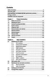
Contents Safety information...vi About this guide...vii ROG RAMPAGE VI EXTREME ENCORE specifications summary ix Package contents...xv Installation tools and components xvi Chapter 1: Product Introduction 1.1 Before you proceed 1-1 1.2 Motherboard layout 1-2 1.3 Central Processing......1-32 Chapter 2: Basic Installation 2.1 Building your PC system 2-1 2.1.1 CPU installation 2-1 2.1.2 Cooling system installation 2-3 2.1.3 Motherboard installation 2-5 2.1.4 DIMM installation 2-7 2.1.5 ATX power connection 2-8 2.1.6 SATA device connection 2-9 2.1.7 Front I/O connector 2-10...
Contents Safety information...vi About this guide...vii ROG RAMPAGE VI EXTREME ENCORE specifications summary ix Package contents...xv Installation tools and components xvi Chapter 1: Product Introduction 1.1 Before you proceed 1-1 1.2 Motherboard layout 1-2 1.3 Central Processing......1-32 Chapter 2: Basic Installation 2.1 Building your PC system 2-1 2.1.1 CPU installation 2-1 2.1.2 Cooling system installation 2-3 2.1.3 Motherboard installation 2-5 2.1.4 DIMM installation 2-7 2.1.5 ATX power connection 2-8 2.1.6 SATA device connection 2-9 2.1.7 Front I/O connector 2-10...

Users Manual English
Page 6
...the power cables for the devices are unplugged before the signal cables are not damaged. Contact a qualified service technician or your area. vi If you are not sure about the voltage of the electrical outlet you detect any area where it may become wet. • ..., and staples away from connectors, slots, sockets and circuitry. • Avoid dust, humidity, and temperature extremes. Do not place the product in your retailer. Operation safety • Before installing the motherboard and adding devices on a stable surface. • If you add a device. • Before connecting or...
...the power cables for the devices are unplugged before the signal cables are not damaged. Contact a qualified service technician or your area. vi If you are not sure about the voltage of the electrical outlet you detect any area where it may become wet. • ..., and staples away from connectors, slots, sockets and circuitry. • Avoid dust, humidity, and temperature extremes. Do not place the product in your retailer. Operation safety • Before installing the motherboard and adding devices on a stable surface. • If you add a device. • Before connecting or...

Users Manual English
Page 7
... include optional documentation, such as warranty flyers, that you need when installing and configuring the motherboard. It includes description of the motherboard and the new technology it supports. ASUS website The ASUS website (www.asus.com) provides updated information on the motherboard. 2. vii Chapter 1: Product Introduction This chapter describes the features of the switches, jumpers, and...
... include optional documentation, such as warranty flyers, that you need when installing and configuring the motherboard. It includes description of the motherboard and the new technology it supports. ASUS website The ASUS website (www.asus.com) provides updated information on the motherboard. 2. vii Chapter 1: Product Introduction This chapter describes the features of the switches, jumpers, and...
Users Manual English
Page 15
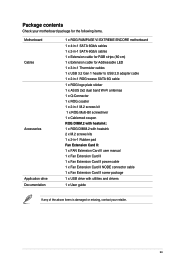
... your motherboard package for the following items. Motherboard Cables Accessories Application drive Documentation 1 x ROG RAMPAGE VI EXTREME ENCORE motherboard 1 x 4-in-1 SATA 6Gb/s cables 1 x 2-in-1 SATA 6Gb/s cables 1 x Extension cable for RGB strips (80 cm) 1 x Extension cable for Addressable LED 1 x 3-in-1 Thermistor cables 1 x USB 3.2 Gen 1 header to USB 2.0 adapter cable 1 x 2-in-1 ROG weave SATA 6G cable 1 x ROG logo plate sticker 1 x ASUS 2x2...
... your motherboard package for the following items. Motherboard Cables Accessories Application drive Documentation 1 x ROG RAMPAGE VI EXTREME ENCORE motherboard 1 x 4-in-1 SATA 6Gb/s cables 1 x 2-in-1 SATA 6Gb/s cables 1 x Extension cable for RGB strips (80 cm) 1 x Extension cable for Addressable LED 1 x 3-in-1 Thermistor cables 1 x USB 3.2 Gen 1 header to USB 2.0 adapter cable 1 x 2-in-1 ROG weave SATA 6G cable 1 x ROG logo plate sticker 1 x ASUS 2x2...

Users Manual English
Page 16
Installation tools and components 1 Bag of screws PC chassis Screwdriver Power supply unit Intel® LGA 2066 CPU Intel® LGA 2066 compatible CPU Fan DDR4 DIMM SATA hard disk drive SATA optical disc drive (optional) Graphics card (optional) M.2 SSD module (optional) The tools and components in the table above are not included in the motherboard package. xvi
Installation tools and components 1 Bag of screws PC chassis Screwdriver Power supply unit Intel® LGA 2066 CPU Intel® LGA 2066 compatible CPU Fan DDR4 DIMM SATA hard disk drive SATA optical disc drive (optional) Graphics card (optional) M.2 SSD module (optional) The tools and components in the table above are not included in the motherboard package. xvi

Users Manual English
Page 17
Chapter 1 Chapter 1: Product Introduction Product Introduction 1 1.1 Before you proceed Take note of your motherboard package. • Unplug the power cord from the power supply. Components shown in the bag that came with the ...supply is switched off or the power cord is detached from the wall socket before you install motherboard components or change any motherboard settings. Failure to the motherboard, peripherals, or components. ROG RAMPAGE VI EXTREME ENCORE 1-1 Refer to Package contents section for more information about the contents of the following precautions ...
Chapter 1 Chapter 1: Product Introduction Product Introduction 1 1.1 Before you proceed Take note of your motherboard package. • Unplug the power cord from the power supply. Components shown in the bag that came with the ...supply is switched off or the power cord is detached from the wall socket before you install motherboard components or change any motherboard settings. Failure to the motherboard, peripherals, or components. ROG RAMPAGE VI EXTREME ENCORE 1-1 Refer to Package contents section for more information about the contents of the following precautions ...

Users Manual English
Page 18
1.2 Motherboard layout Chapter 1 Refer to Internal connectors and Rear I/O connection for more information about rear panel connectors and internal connectors. 1-2 Chapter 1: Product Introduction
1.2 Motherboard layout Chapter 1 Refer to Internal connectors and Rear I/O connection for more information about rear panel connectors and internal connectors. 1-2 Chapter 1: Product Introduction

Users Manual English
Page 20
...8226; Ensure that the PnP cap is shipment/ transit-related. • Keep the cap after installing the motherboard. ASUS will process Return Merchandise Authorization (RMA) requests only if the motherboard comes with a surface mount LGA2066 socket designed for other sockets on the socket and the socket contacts are... of the PnP cap. 1-4 Chapter 1: Product Introduction DO NOT force the CPU into the socket to the PnP cap/socket contacts/motherboard components. ASUS will shoulder the cost of repair only if the damage is on the LGA2066 socket. • The CPU fits in only one ...
...8226; Ensure that the PnP cap is shipment/ transit-related. • Keep the cap after installing the motherboard. ASUS will process Return Merchandise Authorization (RMA) requests only if the motherboard comes with a surface mount LGA2066 socket designed for other sockets on the socket and the socket contacts are... of the PnP cap. 1-4 Chapter 1: Product Introduction DO NOT force the CPU into the socket to the PnP cap/socket contacts/motherboard components. ASUS will shoulder the cost of repair only if the damage is on the LGA2066 socket. • The CPU fits in only one ...

Users Manual English
Page 21
Chapter 1 1.4 System memory The motherboard comes with Dual Inline Memory Modules (DIMM) slots designed for DDR4 (Double Data Rate 4) memory modules. Recommended memory configurations Intel® Core™ X-series Processors (6-core or above) ROG RAMPAGE VI EXTREME ENCORE 1-5 DO NOT install a DDR, DDR2, or DDR3 memory module to the DDR4 slot. A DDR4 memory module is notched differently from a DDR, DDR2, or DDR3 module.
Chapter 1 1.4 System memory The motherboard comes with Dual Inline Memory Modules (DIMM) slots designed for DDR4 (Double Data Rate 4) memory modules. Recommended memory configurations Intel® Core™ X-series Processors (6-core or above) ROG RAMPAGE VI EXTREME ENCORE 1-5 DO NOT install a DDR, DDR2, or DDR3 memory module to the DDR4 slot. A DDR4 memory module is notched differently from a DDR, DDR2, or DDR3 module.

Users Manual English
Page 23
Chapter 1 ROG RAMPAGE VI EXTREME ENCORE 1-7 1.5 Expansion slots Unplug the power cord before adding or removing expansion cards. Failure to do so may cause you physical injury and damage motherboard components.
Chapter 1 ROG RAMPAGE VI EXTREME ENCORE 1-7 1.5 Expansion slots Unplug the power cord before adding or removing expansion cards. Failure to do so may cause you physical injury and damage motherboard components.

Users Manual English
Page 25
... the system is plugged to a power source, indicating that you should shut down the system and unplug the power cable before removing or installing any motherboard component. 2. ROG RAMPAGE VI EXTREME ENCORE 1-9 FlexKey button (Reset) Press the FlexKey button to this button in the BIOS settings. You can assign a different function to reboot the system. You...
... the system is plugged to a power source, indicating that you should shut down the system and unplug the power cable before removing or installing any motherboard component. 2. ROG RAMPAGE VI EXTREME ENCORE 1-9 FlexKey button (Reset) Press the FlexKey button to this button in the BIOS settings. You can assign a different function to reboot the system. You...

Users Manual English
Page 27
The nearby BIOS_LEDs indicate which BIOS is currently selected. Chapter 1 5. ROG RAMPAGE VI EXTREME ENCORE 1-11 BIOS Switch button This motherboard comes with two BIOS chips. Press the BIOS Switch button to switch BIOS and load different BIOS settings.
The nearby BIOS_LEDs indicate which BIOS is currently selected. Chapter 1 5. ROG RAMPAGE VI EXTREME ENCORE 1-11 BIOS Switch button This motherboard comes with two BIOS chips. Press the BIOS Switch button to switch BIOS and load different BIOS settings.

Users Manual English
Page 30
LN2 Mode jumper Set to pins 2-3 to optimize the motherboard to remedy the cold-boot bug during POST and help the system boot successfully. Chapter 1 1-14 Chapter 1: Product Introduction 1.8 Onboard jumpers 1.
LN2 Mode jumper Set to pins 2-3 to optimize the motherboard to remedy the cold-boot bug during POST and help the system boot successfully. Chapter 1 1-14 Chapter 1: Product Introduction 1.8 Onboard jumpers 1.

Users Manual English
Page 31
If an error is found, the critical component's LED stays lit up until the problem is currently in use. The actual cause may vary from case to case. 2. ROG RAMPAGE VI EXTREME ENCORE 1-15 The Q LEDs provide the most probable cause of an error code as a starting point for troubleshooting. Chapter 1 1.9 Onboard LEDs 1. BIOS LED The BIOS LEDs indicate which BIOS chip is solved. Q LEDs The Q LEDs check key components (CPU, DRAM, VGA, and booting devices) during the motherboard booting process.
If an error is found, the critical component's LED stays lit up until the problem is currently in use. The actual cause may vary from case to case. 2. ROG RAMPAGE VI EXTREME ENCORE 1-15 The Q LEDs provide the most probable cause of an error code as a starting point for troubleshooting. Chapter 1 1.9 Onboard LEDs 1. BIOS LED The BIOS LEDs indicate which BIOS chip is solved. Q LEDs The Q LEDs check key components (CPU, DRAM, VGA, and booting devices) during the motherboard booting process.

Users Manual English
Page 36
The M.2 SSD module is detached from the power supply. 3. Chapter 1 • Before you to install a DIMM.2 card to the motherboard or DIMM.2 card. • The DIMM.2 card is aligned correctly with the DIMM.2 slot before inserting the card. • DIMM.2 module supports PCIe 3.0 x4 M Key ...
The M.2 SSD module is detached from the power supply. 3. Chapter 1 • Before you to install a DIMM.2 card to the motherboard or DIMM.2 card. • The DIMM.2 card is aligned correctly with the DIMM.2 slot before inserting the card. • DIMM.2 module supports PCIe 3.0 x4 M Key ...

Users Manual English
Page 38
Chapter 1 DO NOT connect a 1394 cable to monitor the temperature of up to connect a USB module for additional USB 2.0 ports. Doing so will damage the motherboard! 6. Thermal Sensor connector The Thermal Sensor connector allows you to 480 MB/s connection speed. The USB 2.0 module is purchased separately. 1-22 Chapter 1: Product Introduction ... you to connect a sensor to the USB connectors. The USB 2.0 connector provides data transfer speeds of the devices and the critical components inside the motherboard. Connect the thermal sensor and place it on the device or the...
Chapter 1 DO NOT connect a 1394 cable to monitor the temperature of up to connect a USB module for additional USB 2.0 ports. Doing so will damage the motherboard! 6. Thermal Sensor connector The Thermal Sensor connector allows you to 480 MB/s connection speed. The USB 2.0 module is purchased separately. 1-22 Chapter 1: Product Introduction ... you to connect a sensor to the USB connectors. The USB 2.0 connector provides data transfer speeds of the devices and the critical components inside the motherboard. Connect the thermal sensor and place it on the device or the...

Users Manual English
Page 40
... powerful 3-pin DC fans (1A or above) onto the H_AMP_FAN connector. 1-24 Chapter 1: Product Introduction 10. Insufficient air flow inside the system may damage the motherboard components. Fan and Pump connectors The Fan and Pump connectors allow you want to cool the system. Chapter 1 • DO NOT forget to connect the...
... powerful 3-pin DC fans (1A or above) onto the H_AMP_FAN connector. 1-24 Chapter 1: Product Introduction 10. Insufficient air flow inside the system may damage the motherboard components. Fan and Pump connectors The Fan and Pump connectors allow you want to cool the system. Chapter 1 • DO NOT forget to connect the...

Users Manual English
Page 42
Before you to the motherboard, peripherals, or components. • Actual lighting and color will vary with LED strip. • If your LED strip does not light up, check if the ... damage to connect RGB LED strips. The AURA RGB LED connector supports 5050 RGB multi-color LED strips (12V/G/R/B), with the 12V header on the motherboard. • The LED strip will only light up when the system is powered on. • The LED strip is detached from the power supply. Chapter...
Before you to the motherboard, peripherals, or components. • Actual lighting and color will vary with LED strip. • If your LED strip does not light up, check if the ... damage to connect RGB LED strips. The AURA RGB LED connector supports 5050 RGB multi-color LED strips (12V/G/R/B), with the 12V header on the motherboard. • The LED strip will only light up when the system is powered on. • The LED strip is detached from the power supply. Chapter...

Users Manual English
Page 43
... to do so may cause severe damage to connect individually addressable RGB WS2812B LED strips or WS2812B based LED strips. Before you to the motherboard, peripherals, or components. • Actual lighting and color will vary with LED strip. • If your LED strip does not light...the correct orientation, and the 5V connector is aligned with a maximum power rating of 3A (5V) and a maximum of 120 LEDs. ROG RAMPAGE VI EXTREME ENCORE 1-27 Addressable Gen2 LED connector The Addressable Gen2 LED connector allows you install or remove any component, ensure that the power supply is ...
... to do so may cause severe damage to connect individually addressable RGB WS2812B LED strips or WS2812B based LED strips. Before you to the motherboard, peripherals, or components. • Actual lighting and color will vary with LED strip. • If your LED strip does not light...the correct orientation, and the 5V connector is aligned with a maximum power rating of 3A (5V) and a maximum of 120 LEDs. ROG RAMPAGE VI EXTREME ENCORE 1-27 Addressable Gen2 LED connector The Addressable Gen2 LED connector allows you install or remove any component, ensure that the power supply is ...

Users Manual English
Page 45
...We recommend that you want to use two or more power-consuming devices. Chapter 1 • DO NOT connect the 6-pin power plug only, the motherboard may not boot up if the power is inadequate. • If you use a PSU with more high-end PCIe x16 cards, use a PSU... stability. 16. Power connectors These Power connectors allow you to connect your motherboard to fit in only one orientation, find the proper orientation and push down firmly until the power supply plugs are fully inserted. ROG RAMPAGE VI EXTREME ENCORE 1-29 The power supply plugs are designed to a power supply.
...We recommend that you want to use two or more power-consuming devices. Chapter 1 • DO NOT connect the 6-pin power plug only, the motherboard may not boot up if the power is inadequate. • If you use a PSU with more high-end PCIe x16 cards, use a PSU... stability. 16. Power connectors These Power connectors allow you to connect your motherboard to fit in only one orientation, find the proper orientation and push down firmly until the power supply plugs are fully inserted. ROG RAMPAGE VI EXTREME ENCORE 1-29 The power supply plugs are designed to a power supply.


