
MAXIMUS IX FORMULA Users ManualEnglish
Page 1
Motherboard MAXIMUS IX FORMULA
Motherboard MAXIMUS IX FORMULA

MAXIMUS IX FORMULA Users ManualEnglish
Page 3
Contents Safety information...vi About this guide...vii MAXIMUS IX FORMULA specifications summary ix Package contents...xv Installation tools and components xvi Chapter 1: Product Introduction 1.1 Motherboard overview 1-1 1.1.1 Before you proceed 1-1 1.1.2 Motherboard layout 1-2 1.1.3 Central Processing Unit (CPU 1-4 1.1.4 System memory 1-5 1.1.5 Expansion slots 1-7 1.1.6 Onboard buttons and switches 1-9 1.1.7 Onboard LEDs 1-13 1.1.8 Jumper 1-20 1.1.9 Internal connectors 1-21 Chapter 2: Basic Installation 2.1 Building ...
Contents Safety information...vi About this guide...vii MAXIMUS IX FORMULA specifications summary ix Package contents...xv Installation tools and components xvi Chapter 1: Product Introduction 1.1 Motherboard overview 1-1 1.1.1 Before you proceed 1-1 1.1.2 Motherboard layout 1-2 1.1.3 Central Processing Unit (CPU 1-4 1.1.4 System memory 1-5 1.1.5 Expansion slots 1-7 1.1.6 Onboard buttons and switches 1-9 1.1.7 Onboard LEDs 1-13 1.1.8 Jumper 1-20 1.1.9 Internal connectors 1-21 Chapter 2: Basic Installation 2.1 Building ...

MAXIMUS IX FORMULA Users ManualEnglish
Page 6
... any damage, contact your dealer immediately. • To avoid short circuits, keep paper clips, screws, and staples away from the motherboard, ensure that all cables are correctly connected and the power cables are not damaged. If you add a device. • Before ...signal cables from connectors, slots, sockets and circuitry. • Avoid dust, humidity, and temperature extremes. Operation safety • Before installing the motherboard and adding devices on a stable surface. • If you are using, contact your retailer. Safety information Electrical safety • To prevent ...
... any damage, contact your dealer immediately. • To avoid short circuits, keep paper clips, screws, and staples away from the motherboard, ensure that all cables are correctly connected and the power cables are not damaged. If you add a device. • Before ...signal cables from connectors, slots, sockets and circuitry. • Avoid dust, humidity, and temperature extremes. Operation safety • Before installing the motherboard and adding devices on a stable surface. • If you are using, contact your retailer. Safety information Electrical safety • To prevent ...

MAXIMUS IX FORMULA Users ManualEnglish
Page 7
... your dealer. It includes description of the switches, jumpers, and connectors on ASUS hardware and software products. 2. ASUS website The ASUS website (www.asus.com) provides updated information on the motherboard. • Chapter 2: Basic Installation This chapter lists the hardware setup procedures ... 4: RAID Support This chapter describes the RAID configurations. Detailed descriptions of the BIOS parameters are not part of the motherboard and the new technology it supports. Optional documentation Your product package may include optional documentation, such as warranty flyers, that...
... your dealer. It includes description of the switches, jumpers, and connectors on ASUS hardware and software products. 2. ASUS website The ASUS website (www.asus.com) provides updated information on the motherboard. • Chapter 2: Basic Installation This chapter lists the hardware setup procedures ... 4: RAID Support This chapter describes the RAID configurations. Detailed descriptions of the BIOS parameters are not part of the motherboard and the new technology it supports. Optional documentation Your product package may include optional documentation, such as warranty flyers, that...
MAXIMUS IX FORMULA Users ManualEnglish
Page 9
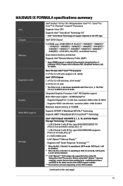
...Chipset 1 x PCIe 3.0 x16 slot (max. The PCIe 3.0 x4_3 is subject to the latest version from ASUS support website. ****This function will be disabled. ** When the M.2_2 Socket 3 is operating in PCIe ...when using Intel® Optane™ memory modules, ensure that you have updated your motherboard drivers and BIOS to the physical characteristics of 1024MB Supports NVIDIA® 2-Way/Quad...Processor- Before using 7th Generation Intel® Processors. MAXIMUS IX FORMULA specifications summary CPU Chipset Memory Expansion slots Graphic Multi-GPU support Storage Intel® Socket 1151 ...
...Chipset 1 x PCIe 3.0 x16 slot (max. The PCIe 3.0 x4_3 is subject to the latest version from ASUS support website. ****This function will be disabled. ** When the M.2_2 Socket 3 is operating in PCIe ...when using Intel® Optane™ memory modules, ensure that you have updated your motherboard drivers and BIOS to the physical characteristics of 1024MB Supports NVIDIA® 2-Way/Quad...Processor- Before using 7th Generation Intel® Processors. MAXIMUS IX FORMULA specifications summary CPU Chipset Memory Expansion slots Graphic Multi-GPU support Storage Intel® Socket 1151 ...

MAXIMUS IX FORMULA Users ManualEnglish
Page 15
Package contents Check your motherboard package for the following items. Motherboard Cables Accessories Application DVD Documentation ROG MAXIMUS IX FORMULA 3 x 2-in-1 SATA 6 Gb/s cables 1 x Extension Cable for RGB Strips (80cm) 1 x 2x2 dual-band Wi-Fi moving antennas 1 x 10-in-1 ROG cable label 1 x CPU Installation tool 1 x SLI® HB bridge (2-WAY-M) 1 x M.2 bracket 1 x M.2 screw package 1 x Q-connector 1 x ROG coaster 1 x ROG sticker ROG motherboard support DVD User guide If any of the above items is damaged or missing, contact your retailer. xv
Package contents Check your motherboard package for the following items. Motherboard Cables Accessories Application DVD Documentation ROG MAXIMUS IX FORMULA 3 x 2-in-1 SATA 6 Gb/s cables 1 x Extension Cable for RGB Strips (80cm) 1 x 2x2 dual-band Wi-Fi moving antennas 1 x 10-in-1 ROG cable label 1 x CPU Installation tool 1 x SLI® HB bridge (2-WAY-M) 1 x M.2 bracket 1 x M.2 screw package 1 x Q-connector 1 x ROG coaster 1 x ROG sticker ROG motherboard support DVD User guide If any of the above items is damaged or missing, contact your retailer. xv

MAXIMUS IX FORMULA Users ManualEnglish
Page 16
xvi Installation tools and components 1 Bag of screws Phillips (cross) screwdriver PC chassis Power supply unit Intel® LGA 1151 CPU Intel® LGA 1151 compatible CPU Fan DDR4 DIMM SATA hard disk drive SATA optical disc drive (optional) Graphics card (optional) The tools and components in the table above are not included in the motherboard package.
xvi Installation tools and components 1 Bag of screws Phillips (cross) screwdriver PC chassis Power supply unit Intel® LGA 1151 CPU Intel® LGA 1151 compatible CPU Fan DDR4 DIMM SATA hard disk drive SATA optical disc drive (optional) Graphics card (optional) The tools and components in the table above are not included in the motherboard package.

MAXIMUS IX FORMULA Users ManualEnglish
Page 17
...cord is detached from the wall socket before you uninstall any motherboard settings. • Unplug the power cord from the power supply. Chapter 1 Chapter 1: Product Introduction Product Introduction 1 1.1 Motherboard overview 1.1.1 Before you proceed Take note of the following precautions ... such as the power supply case, to avoid damaging them . • Whenever you install motherboard components or change any component, place it on them due to static electricity. • Hold components by the edges to the motherboard, peripherals, or components. ASUS MAXIMUS IX FORMULA 1-1
...cord is detached from the wall socket before you uninstall any motherboard settings. • Unplug the power cord from the power supply. Chapter 1 Chapter 1: Product Introduction Product Introduction 1 1.1 Motherboard overview 1.1.1 Before you proceed Take note of the following precautions ... such as the power supply case, to avoid damaging them . • Whenever you install motherboard components or change any component, place it on them due to static electricity. • Hold components by the edges to the motherboard, peripherals, or components. ASUS MAXIMUS IX FORMULA 1-1

MAXIMUS IX FORMULA Users ManualEnglish
Page 18
1.1.2 Motherboard layout Chapter 1 Refer to 1.1.9 Internal connectors and 2.3.1 Rear I/O connection for more information about rear panel connectors and internal connectors. 1-2 Chapter 1: Product Introduction
1.1.2 Motherboard layout Chapter 1 Refer to 1.1.9 Internal connectors and 2.3.1 Rear I/O connection for more information about rear panel connectors and internal connectors. 1-2 Chapter 1: Product Introduction

MAXIMUS IX FORMULA Users ManualEnglish
Page 20
... installing the CPU. • Upon purchase of the motherboard, ensure that you see any damage to the PnP cap/socket contacts/motherboard components. ASUS will process Return Merchandise Authorization (RMA) requests only if the motherboard comes with memory and PCI Express controllers integrated to support... dual-channel (4 DIMM) DDR4 memory and 16 PCI Express 3.0/2.0 lanes. ASUS will shoulder the cost of the PnP cap. 1-4 Chapter 1: Product Introduction 1.1.3 Central Processing Unit (CPU) This motherboard supports the New 7th / 6th Gen Intel® Core™ processors on the...
... installing the CPU. • Upon purchase of the motherboard, ensure that you see any damage to the PnP cap/socket contacts/motherboard components. ASUS will process Return Merchandise Authorization (RMA) requests only if the motherboard comes with memory and PCI Express controllers integrated to support... dual-channel (4 DIMM) DDR4 memory and 16 PCI Express 3.0/2.0 lanes. ASUS will shoulder the cost of the PnP cap. 1-4 Chapter 1: Product Introduction 1.1.3 Central Processing Unit (CPU) This motherboard supports the New 7th / 6th Gen Intel® Core™ processors on the...

MAXIMUS IX FORMULA Users ManualEnglish
Page 21
Chapter 1 1.1.4 System memory The motherboard comes with four Double Data Rate 4 (DDR4) Dual Inline Memory Modules (DIMM) slots. DO NOT install a DDR, DDR2, or DDR3 memory module to the DDR4 slot. A DDR4 module is notched differently from a DDR, DDR2, or DDR3 module. Recommended memory configurations ASUS MAXIMUS IX FORMULA 1-5
Chapter 1 1.1.4 System memory The motherboard comes with four Double Data Rate 4 (DDR4) Dual Inline Memory Modules (DIMM) slots. DO NOT install a DDR, DDR2, or DDR3 memory module to the DDR4 slot. A DDR4 module is notched differently from a DDR, DDR2, or DDR3 module. Recommended memory configurations ASUS MAXIMUS IX FORMULA 1-5

MAXIMUS IX FORMULA Users ManualEnglish
Page 22
... For effective use a more memory on its Serial Presence Detect (SPD), which is subject to the motherboard. • The default memory operation frequency is dependent on the motherboard, the actual usable memory for overclocking may operate at http://support.microsoft. com/kb/929605/en-us.... • Memory modules with the same CAS latency. Load the X.M.P. Ensure that you want to get the correct memory modules. • ASUS exclusively provides hyper DIMM support function. • Hyper DIMM support is the standard way of the lower-sized channel for the latest QVL. ...
... For effective use a more memory on its Serial Presence Detect (SPD), which is subject to the motherboard. • The default memory operation frequency is dependent on the motherboard, the actual usable memory for overclocking may operate at http://support.microsoft. com/kb/929605/en-us.... • Memory modules with the same CAS latency. Load the X.M.P. Ensure that you want to get the correct memory modules. • ASUS exclusively provides hyper DIMM support function. • Hyper DIMM support is the standard way of the lower-sized channel for the latest QVL. ...

MAXIMUS IX FORMULA Users ManualEnglish
Page 23
Failure to do so may cause you physical injury and damage motherboard components. Slot Description 1 PCIe 3.0 x1_1 slot 2 PCIe 3.0 x16/x8_1 slot 3 PCIe 3.0 x1_2 slot 4 PCIe 3.0 x8_2 slot 5 PCIe 3.0 x1_3 slot 6 PCIe 3.0 x4_3 slot ASUS MAXIMUS IX FORMULA 1-7 Chapter 1 Slot No. 1.1.5 Expansion slots Unplug the power cord before adding or removing expansion cards.
Failure to do so may cause you physical injury and damage motherboard components. Slot Description 1 PCIe 3.0 x1_1 slot 2 PCIe 3.0 x16/x8_1 slot 3 PCIe 3.0 x1_2 slot 4 PCIe 3.0 x8_2 slot 5 PCIe 3.0 x1_3 slot 6 PCIe 3.0 x4_3 slot ASUS MAXIMUS IX FORMULA 1-7 Chapter 1 Slot No. 1.1.5 Expansion slots Unplug the power cord before adding or removing expansion cards.

MAXIMUS IX FORMULA Users ManualEnglish
Page 24
shared - - - - - - shared - - - - - High Definition Audio shared - - - - - - - ASMedia 2142-1 shared - - - - - - - PCIe_x16/x8_1 slot switches to the motherboard connector labeled CHA_FAN1-4 when using multiple graphics cards for this motherboard A B C D E F G H PCIEX16/X8_1 shared - - - - - - - PCIEX8_2 - I.G.F.X. Intel LAN Controller shared - - - - - - - VGA Configuration PCIe operating mode PCIe_x16/x8_1 PCIe_x8_2 Single VGA/PCIe card x16 (Recommend for single VGA) N/A ...
shared - - - - - - shared - - - - - High Definition Audio shared - - - - - - - ASMedia 2142-1 shared - - - - - - - PCIe_x16/x8_1 slot switches to the motherboard connector labeled CHA_FAN1-4 when using multiple graphics cards for this motherboard A B C D E F G H PCIEX16/X8_1 shared - - - - - - - PCIEX8_2 - I.G.F.X. Intel LAN Controller shared - - - - - - - VGA Configuration PCIe operating mode PCIe_x16/x8_1 PCIe_x8_2 Single VGA/PCIe card x16 (Recommend for single VGA) N/A ...

MAXIMUS IX FORMULA Users ManualEnglish
Page 25
Power-on button (START) The motherboard comes with a power-on a bare or open-case system. The LED near the button also lights up the system. ASUS MAXIMUS IX FORMULA 1-9 RESET button (RESET) Press the reset button to enhance system performance. 1. This is plugged to ...a power source indicating that allows you should shut down the system and unplug the power cable before removing or installing any motherboard component. 2. Chapter ...
Power-on button (START) The motherboard comes with a power-on a bare or open-case system. The LED near the button also lights up the system. ASUS MAXIMUS IX FORMULA 1-9 RESET button (RESET) Press the reset button to enhance system performance. 1. This is plugged to ...a power source indicating that allows you should shut down the system and unplug the power cable before removing or installing any motherboard component. 2. Chapter ...

MAXIMUS IX FORMULA Users ManualEnglish
Page 26
...seconds for about 5-10 seconds. • If your system fails to the latest BIOS version from www.asus.com after using the MemOK! To stop memory tuning, turn off the computer and replace DIMMs during POST ... with ones recommended in the Memory QVL (Qualified Vendors Lists) in this user manual or at www.asus.com. • If you download and update to boot up when the DIMM is tested. Turn off... cord for the system to boot and load the BIOS default settings. Replace the DIMMs with the motherboard may cause system boot failure, and the DRAM_LED near the MemOK! If the test fails, the ...
...seconds for about 5-10 seconds. • If your system fails to the latest BIOS version from www.asus.com after using the MemOK! To stop memory tuning, turn off the computer and replace DIMMs during POST ... with ones recommended in the Memory QVL (Qualified Vendors Lists) in this user manual or at www.asus.com. • If you download and update to boot up when the DIMM is tested. Turn off... cord for the system to boot and load the BIOS default settings. Replace the DIMMs with the motherboard may cause system boot failure, and the DRAM_LED near the MemOK! If the test fails, the ...

MAXIMUS IX FORMULA Users ManualEnglish
Page 29
Chapter 1 1.1.7 Onboard LEDs 1. ASUS MAXIMUS IX FORMULA 1-13 Button LEDs (BTN_LED1-2) These LEDs are designed to locate the root problem within seconds. 2. If an error is found, the corresponding LED remains lit until the problem is solved. This user-friendly design provides an intuitive way to indicate the location of the START and RESET buttons. Q LEDs (BOOT_DEVICE_LED, VGA_LED, DRAM_LED, CPU_LED) Q LEDs check key components (CPU, DRAM, VGA card, and booting devices) in sequence during motherboard booting process.
Chapter 1 1.1.7 Onboard LEDs 1. ASUS MAXIMUS IX FORMULA 1-13 Button LEDs (BTN_LED1-2) These LEDs are designed to locate the root problem within seconds. 2. If an error is found, the corresponding LED remains lit until the problem is solved. This user-friendly design provides an intuitive way to indicate the location of the START and RESET buttons. Q LEDs (BOOT_DEVICE_LED, VGA_LED, DRAM_LED, CPU_LED) Q LEDs check key components (CPU, DRAM, VGA card, and booting devices) in sequence during motherboard booting process.

MAXIMUS IX FORMULA Users ManualEnglish
Page 36
Chapter 1 1-20 Chapter 1: Product Introduction 1.1.8 Jumper 1. LN2 Mode jumper (3-pin LN2_MODE) With LN2 mode activated, the ROG motherboard is optimized to remedy the cold-boot bug during POST and help the system boot successfully.
Chapter 1 1-20 Chapter 1: Product Introduction 1.1.8 Jumper 1. LN2 Mode jumper (3-pin LN2_MODE) With LN2 mode activated, the ROG motherboard is optimized to remedy the cold-boot bug during POST and help the system boot successfully.

MAXIMUS IX FORMULA Users ManualEnglish
Page 37
...® Z270 Serial ATA 6 Gb/s connectors (7-pin SATA6G_12; ASUS MAXIMUS IX FORMULA 1-21 If you can create a RAID 0, 1, 5, and 10 configuration with the Intel® Rapid Storage Technology through the onboard Intel® Z270 chipset. • These connectors are set the SATA Mode in the motherboard support DVD. • When using NCQ, set to Serial...
...® Z270 Serial ATA 6 Gb/s connectors (7-pin SATA6G_12; ASUS MAXIMUS IX FORMULA 1-21 If you can create a RAID 0, 1, 5, and 10 configuration with the Intel® Rapid Storage Technology through the onboard Intel® Z270 chipset. • These connectors are set the SATA Mode in the motherboard support DVD. • When using NCQ, set to Serial...

MAXIMUS IX FORMULA Users ManualEnglish
Page 39
Connect the USB module cable to this connector, then install the module to 480 MBps connection speed. ASUS MAXIMUS IX FORMULA 1-23 This USB connector complies with USB 2.0 specification that supports up to a slot opening at mid-board shares pins with ROG extension (ROG_EXT) port. Doing so will damage the motherboard! 1 x USB 2.0 port (USB1314) at the back of the system chassis. Never connect a 1394 cable to the USB connectors. Chapter 1 4. USB 2.0 connector (10-1 pin USB1314) This connector is for USB 2.0 port.
Connect the USB module cable to this connector, then install the module to 480 MBps connection speed. ASUS MAXIMUS IX FORMULA 1-23 This USB connector complies with USB 2.0 specification that supports up to a slot opening at mid-board shares pins with ROG extension (ROG_EXT) port. Doing so will damage the motherboard! 1 x USB 2.0 port (USB1314) at the back of the system chassis. Never connect a 1394 cable to the USB connectors. Chapter 1 4. USB 2.0 connector (10-1 pin USB1314) This connector is for USB 2.0 port.


