Users Manual English
Page 3
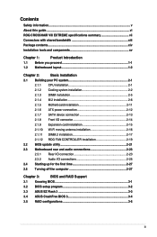
...ROG CROSSHAIR VIII EXTREME specifications summary vii Connectors with shared bandwidth xiii Package contents...xiv Installation tools and components xv Chapter 1: Product Introduction 1.1 Before you proceed 1-1 1.2 Motherboard layout 1-2 Chapter 2: Basic Installation 2.1 Building your PC system 2-1 2.1.1 CPU installation 2-1 2.1.2 Cooling system installation 2-2 2.1.3 DIMM installation 2-5 2.1.4 M.2 installation 2-6 2.1.5 Motherboard...installation 2-17 2.1.12 ROG FAN CONTROLLER installation 2-19 2.2 BIOS update utility 2-21 2.3 Motherboard rear and audio connections ...
...ROG CROSSHAIR VIII EXTREME specifications summary vii Connectors with shared bandwidth xiii Package contents...xiv Installation tools and components xv Chapter 1: Product Introduction 1.1 Before you proceed 1-1 1.2 Motherboard layout 1-2 Chapter 2: Basic Installation 2.1 Building your PC system 2-1 2.1.1 CPU installation 2-1 2.1.2 Cooling system installation 2-2 2.1.3 DIMM installation 2-5 2.1.4 M.2 installation 2-6 2.1.5 Motherboard...installation 2-17 2.1.12 ROG FAN CONTROLLER installation 2-19 2.2 BIOS update utility 2-21 2.3 Motherboard rear and audio connections ...

Users Manual English
Page 5
...are not sure about the voltage of the electrical outlet you add a device. • Before connecting or removing signal cables from the motherboard, ensure that all cables are correctly connected and the power cables are unplugged. • Seek professional assistance before using , contact your ...circuits, keep paper clips, screws, and staples away from connectors, slots, sockets and circuitry. • Avoid dust, humidity, and temperature extremes. Contact a qualified service technician or your power supply is broken, do not try to or from the existing system before the signal cables ...
...are not sure about the voltage of the electrical outlet you add a device. • Before connecting or removing signal cables from the motherboard, ensure that all cables are correctly connected and the power cables are unplugged. • Seek professional assistance before using , contact your ...circuits, keep paper clips, screws, and staples away from connectors, slots, sockets and circuitry. • Avoid dust, humidity, and temperature extremes. Contact a qualified service technician or your power supply is broken, do not try to or from the existing system before the signal cables ...
Users Manual English
Page 6
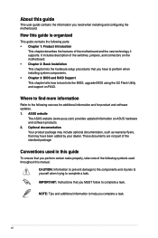
...guide contains the following parts: • Chapter 1: Product Introduction This chapter describes the features of the standard package. ASUS website The ASUS website (www.asus.com) provides updated information on RAID. NOTE: Tips and additional information to boot into the BIOS, upgrade BIOS using...components. • Chapter 3: BIOS and RAID Support This chapter tells how to help you need when installing and configuring the motherboard. CAUTION: Information to prevent damage to the components and injuries to yourself when trying to the following symbols used throughout this manual...
...guide contains the following parts: • Chapter 1: Product Introduction This chapter describes the features of the standard package. ASUS website The ASUS website (www.asus.com) provides updated information on RAID. NOTE: Tips and additional information to boot into the BIOS, upgrade BIOS using...components. • Chapter 3: BIOS and RAID Support This chapter tells how to help you need when installing and configuring the motherboard. CAUTION: Information to prevent damage to the components and injuries to yourself when trying to the following symbols used throughout this manual...
Users Manual English
Page 14
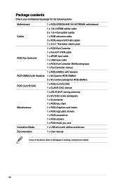
... motherboard package for the following items. Motherboard 1 x ROG CROSSHAIR VIII EXTREME motherboard Cables 1 x 1-to-3 ARGB splitter cable 2 x 1-to-4 fan splitter cables 1 x RGB extension cable 3 x ROG weave SATA 6G cables 1 x 3-in-1 Thermistor cables pack ROG Fan Controller 1 x ROG Fan Controller 1 x Fan EXT PWR cable 1 x ARGB input cable 1 x USB input cable 1 x ROG Fan Controller 3M Mounting tape 1 x Fan Controller manual ROG DIMM.2 with Heatsink 1 x ROG...
... motherboard package for the following items. Motherboard 1 x ROG CROSSHAIR VIII EXTREME motherboard Cables 1 x 1-to-3 ARGB splitter cable 2 x 1-to-4 fan splitter cables 1 x RGB extension cable 3 x ROG weave SATA 6G cables 1 x 3-in-1 Thermistor cables pack ROG Fan Controller 1 x ROG Fan Controller 1 x Fan EXT PWR cable 1 x ARGB input cable 1 x USB input cable 1 x ROG Fan Controller 3M Mounting tape 1 x Fan Controller manual ROG DIMM.2 with Heatsink 1 x ROG...

Users Manual English
Page 15
xv Installation tools and components PC chassis Phillips (cross) screwdriver Power supply unit AMD AM4 CPU AMD AM4 compatible CPU Fan DDR4 DIMM SATA hard disk drive SATA optical disc drive (optional) Graphics card (optional) M.2 SSD module (optional) 1 Bag of screws The tools and components in the table above are not included in the motherboard package.
xv Installation tools and components PC chassis Phillips (cross) screwdriver Power supply unit AMD AM4 CPU AMD AM4 compatible CPU Fan DDR4 DIMM SATA hard disk drive SATA optical disc drive (optional) Graphics card (optional) M.2 SSD module (optional) 1 Bag of screws The tools and components in the table above are not included in the motherboard package.

Users Manual English
Page 17
ROG CROSSHAIR VIII EXTREME 1-1 Chapter 1 Chapter 1: Product Introduction Product Introduction 1 1.1 Before you proceed Take note of the following precautions before you install motherboard components or change any motherboard settings. • Unplug the power cord from the wall socket before touching any component. • Before ...as the power supply case, to avoid damaging them due to static electricity. • Hold components by the edges to the motherboard, peripherals, or components. Failure to do so may cause severe damage to avoid touching the ICs on them. • Whenever...
ROG CROSSHAIR VIII EXTREME 1-1 Chapter 1 Chapter 1: Product Introduction Product Introduction 1 1.1 Before you proceed Take note of the following precautions before you install motherboard components or change any motherboard settings. • Unplug the power cord from the wall socket before touching any component. • Before ...as the power supply case, to avoid damaging them due to static electricity. • Hold components by the edges to the motherboard, peripherals, or components. Failure to do so may cause severe damage to avoid touching the ICs on them. • Whenever...

Users Manual English
Page 18
1.2 Motherboard layout Chapter 1 1-2 Chapter 1: Product Introduction
1.2 Motherboard layout Chapter 1 1-2 Chapter 1: Product Introduction

Users Manual English
Page 20
... / 5000 G-Series / 4000 G-Series / 3000 Series / 3000 G-Series / 2000 Series / 2000 G-Series Desktop Processors. • The AM4 socket has a different pinout design. CPU socket The motherboard comes with a AMD Socket AM4 designed for the AM4 socket. • The CPU fits in only one correct orientation. Chapter 1 1. Ensure that all power cables...
... / 5000 G-Series / 4000 G-Series / 3000 Series / 3000 G-Series / 2000 Series / 2000 G-Series Desktop Processors. • The AM4 socket has a different pinout design. CPU socket The motherboard comes with a AMD Socket AM4 designed for the AM4 socket. • The CPU fits in only one correct orientation. Chapter 1 1. Ensure that all power cables...

Users Manual English
Page 21
Recommended memory configurations ROG CROSSHAIR VIII EXTREME 1-5 DO NOT install a DDR, DDR2, or DDR3 memory module to the DDR4 slot. Chapter 1 2. A DDR4 memory module is notched differently from a DDR, DDR2, or DDR3 module. DIMM slots The motherboard comes with Dual Inline Memory Modules (DIMM) slots designed for DDR4 (Double Data Rate 4) memory modules.
Recommended memory configurations ROG CROSSHAIR VIII EXTREME 1-5 DO NOT install a DDR, DDR2, or DDR3 memory module to the DDR4 slot. Chapter 1 2. A DDR4 memory module is notched differently from a DDR, DDR2, or DDR3 module. DIMM slots The motherboard comes with Dual Inline Memory Modules (DIMM) slots designed for DDR4 (Double Data Rate 4) memory modules.

Users Manual English
Page 23
Failure to the following table for the recommended VGA configuration. Chapter 1 Please refer to do so may cause you physical injury and damage motherboard components. ROG CROSSHAIR VIII EXTREME 1-7 Expansion slots Unplug the power cord before adding or removing expansion cards. 3.
Failure to the following table for the recommended VGA configuration. Chapter 1 Please refer to do so may cause you physical injury and damage motherboard components. ROG CROSSHAIR VIII EXTREME 1-7 Expansion slots Unplug the power cord before adding or removing expansion cards. 3.
Users Manual English
Page 25
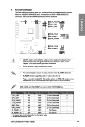
... place jumper caps on the fan headers! • Ensure the cable is connected to the fan headers. ROG CROSSHAIR VIII EXTREME 1-9 CHA_FAN1P, and CHA_FAN2P can support ASUS HYDRANODE fans. Fan and Pump headers The Fan and Pump headers allow you to connect fans or pumps to...jumpers! Insufficient air flow inside the system may damage the motherboard components. Chapter 1 • DO NOT forget to connect the fan cables to a ASUS HYDRANODE fan connector, the ASUS HYDRANODE function will be available. When an ASUS HYDRANODE fan is fully inserted into the header. • ...
... place jumper caps on the fan headers! • Ensure the cable is connected to the fan headers. ROG CROSSHAIR VIII EXTREME 1-9 CHA_FAN1P, and CHA_FAN2P can support ASUS HYDRANODE fans. Fan and Pump headers The Fan and Pump headers allow you to connect fans or pumps to...jumpers! Insufficient air flow inside the system may damage the motherboard components. Chapter 1 • DO NOT forget to connect the fan cables to a ASUS HYDRANODE fan connector, the ASUS HYDRANODE function will be available. When an ASUS HYDRANODE fan is fully inserted into the header. • ...

Users Manual English
Page 27
... connector. The power supply plugs are fully inserted. ROG CROSSHAIR VIII EXTREME 1-11 The system may become unstable or may not boot up if the power is inadequate. • If you to connect your PCIe X16 slots and also provides power for PD3.0 support for your motherboard to ensure the system stability. 7. Power connectors These...
... connector. The power supply plugs are fully inserted. ROG CROSSHAIR VIII EXTREME 1-11 The system may become unstable or may not boot up if the power is inadequate. • If you to connect your PCIe X16 slots and also provides power for PD3.0 support for your motherboard to ensure the system stability. 7. Power connectors These...
Users Manual English
Page 30
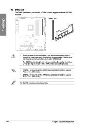
Failure to do so may cause severe damage to the motherboard or DIMM.2 card. • The DIMM.2 card is notched to support additional M.2 SSD modules. Ensure that the power supply is switched off or the power ... is aligned correctly with the DIMM.2 slot before inserting the card. • DIMM.2_1 slot (Key M) via ROG DIMM.2, type 2242/2260/2280/22110 (supports PCIe 4.0 x4 & SATA modes) • DIMM.2_2 slot (Key M) via ROG DIMM.2, type 2242/2260/2280/22110 (supports PCIe 4.0 x4 & SATA modes) The M.2 SSD module is detached...
Failure to do so may cause severe damage to the motherboard or DIMM.2 card. • The DIMM.2 card is notched to support additional M.2 SSD modules. Ensure that the power supply is switched off or the power ... is aligned correctly with the DIMM.2 slot before inserting the card. • DIMM.2_1 slot (Key M) via ROG DIMM.2, type 2242/2260/2280/22110 (supports PCIe 4.0 x4 & SATA modes) • DIMM.2_2 slot (Key M) via ROG DIMM.2, type 2242/2260/2280/22110 (supports PCIe 4.0 x4 & SATA modes) The M.2 SSD module is detached...

Users Manual English
Page 33
The USB 2.0 header provides data transfer speeds of up to the USB connectors. Doing so will damage the motherboard! Chapter 1 14. ROG CROSSHAIR VIII EXTREME 1-17 DO NOT connect a 1394 cable to 480 Mb/s connection speed. The USB 2.0 module is purchased separately. USB 2.0 header The USB 2.0 header allows you to connect a USB module for additional USB 2.0 ports.
The USB 2.0 header provides data transfer speeds of up to the USB connectors. Doing so will damage the motherboard! Chapter 1 14. ROG CROSSHAIR VIII EXTREME 1-17 DO NOT connect a 1394 cable to 480 Mb/s connection speed. The USB 2.0 module is purchased separately. USB 2.0 header The USB 2.0 header allows you to connect a USB module for additional USB 2.0 ports.

Users Manual English
Page 34
15. Before you to the motherboard, peripherals, or components. • Actual lighting and color will only light up , check if the addressable RGB LED strip is connected in the correct orientation, ... or WS2812B based LED strips. Chapter 1 The Addressable Gen2 header supports WS2812B addressable RGB LED strips (5V/ Data/Ground), with the 5V header on the motherboard. • The addressable RGB LED strip will vary with LED strip. • If your LED strip does not light up when the system is powered...
15. Before you to the motherboard, peripherals, or components. • Actual lighting and color will only light up , check if the addressable RGB LED strip is connected in the correct orientation, ... or WS2812B based LED strips. Chapter 1 The Addressable Gen2 header supports WS2812B addressable RGB LED strips (5V/ Data/Ground), with the 5V header on the motherboard. • The addressable RGB LED strip will vary with LED strip. • If your LED strip does not light up when the system is powered...

Users Manual English
Page 35
Chapter 1 The AURA RGB header supports 5050 RGB multi-color LED strips (12V/G/R/B), with the 12V header on the motherboard. • The LED strip will vary with LED strip. • If your LED strip does not light up, check if the RGB LED extension ...component, ensure that the power supply is switched off or the power cord is purchased separately. Before you to the motherboard, peripherals, or components. • Actual lighting and color will only light up when the system is powered on. • The LED strip is detached from the power supply. ROG CROSSHAIR VIII EXTREME 1-19 16.
Chapter 1 The AURA RGB header supports 5050 RGB multi-color LED strips (12V/G/R/B), with the 12V header on the motherboard. • The LED strip will vary with LED strip. • If your LED strip does not light up, check if the RGB LED extension ...component, ensure that the power supply is switched off or the power cord is purchased separately. Before you to the motherboard, peripherals, or components. • Actual lighting and color will only light up when the system is powered on. • The LED strip is detached from the power supply. ROG CROSSHAIR VIII EXTREME 1-19 16.

Users Manual English
Page 36
Chapter 1 The nearby BIOS_LEDs indicate which BIOS is currently selected. 18. FlexKey button (Reset) Press the FlexKey button to the button. BIOS Switch button This motherboard comes with two BIOS chips. You may also configure the button and assign a quick access feature such as activating Safe Boot or turning Aura lighting ...
Chapter 1 The nearby BIOS_LEDs indicate which BIOS is currently selected. 18. FlexKey button (Reset) Press the FlexKey button to the button. BIOS Switch button This motherboard comes with two BIOS chips. You may also configure the button and assign a quick access feature such as activating Safe Boot or turning Aura lighting ...

Users Manual English
Page 37
LN2 Mode jumper Set to pins 2-3 to optimize the motherboard to this header. Front Panel Audio header The Front Panel Audio header is for a chassis-mounted front panel audio I/O module that you connect a high-definition front panel audio module to this connector to avail of the front panel audio I/O module cable to remedy the cold-boot bug during POST and help the system boot successfully. We recommend that supports HD Audio. ROG CROSSHAIR VIII EXTREME 1-21 Connect one end of the motherboard's high-definition audio capability. 20. Chapter 1 19.
LN2 Mode jumper Set to pins 2-3 to optimize the motherboard to this header. Front Panel Audio header The Front Panel Audio header is for a chassis-mounted front panel audio I/O module that you connect a high-definition front panel audio module to this connector to avail of the front panel audio I/O module cable to remedy the cold-boot bug during POST and help the system boot successfully. We recommend that supports HD Audio. ROG CROSSHAIR VIII EXTREME 1-21 Connect one end of the motherboard's high-definition audio capability. 20. Chapter 1 19.

Users Manual English
Page 38
You can also measure the ProbeIt points during overclocking. The illustration above is for reference only, the actual motherboard layout and measure points may differ by model. 1-22 Chapter 1: Product Introduction ProbeIt Measurement Points The ROG ProbeIt allows you to measure the corresponding voltage information. Chapter 1 Using ProbeIt Connect one of the probe onto the GND ProbeIt point, then connect the other probe onto another ProbeIt point to detect your system's current voltage and OC settings using a multimeter. 21.
You can also measure the ProbeIt points during overclocking. The illustration above is for reference only, the actual motherboard layout and measure points may differ by model. 1-22 Chapter 1: Product Introduction ProbeIt Measurement Points The ROG ProbeIt allows you to measure the corresponding voltage information. Chapter 1 Using ProbeIt Connect one of the probe onto the GND ProbeIt point, then connect the other probe onto another ProbeIt point to detect your system's current voltage and OC settings using a multimeter. 21.

Users Manual English
Page 41
An LED near the button also lights up the system, or put the system into sleep or soft-off mode (depending on the operating system settings). Chapter 1 25. Start button Press the Start button to power up when the system is plugged to a power source, indicating that you should shut down the system and unplug the power cable before removing or installing any motherboard component ROG CROSSHAIR VIII EXTREME 1-25
An LED near the button also lights up the system, or put the system into sleep or soft-off mode (depending on the operating system settings). Chapter 1 25. Start button Press the Start button to power up when the system is plugged to a power source, indicating that you should shut down the system and unplug the power cable before removing or installing any motherboard component ROG CROSSHAIR VIII EXTREME 1-25


