Users Manual English
Page 3
Contents Safety information...vi About this guide...vii ROG CROSSHAIR VII HERO specifications summary ix Package contents...xv Installation tools and components xvi Chapter 1: Product Introduction 1.1 Motherboard overview 1-1 1.1.1 Before you proceed 1-1 1.1.2 Motherboard layout 1-2 1.1.3 Central Processing Unit (CPU 1-4 1.1.4 System memory 1-5 1.1.5 Expansion slots 1-7 1.1.6 Onboard buttons and ...
Contents Safety information...vi About this guide...vii ROG CROSSHAIR VII HERO specifications summary ix Package contents...xv Installation tools and components xvi Chapter 1: Product Introduction 1.1 Motherboard overview 1-1 1.1.1 Before you proceed 1-1 1.1.2 Motherboard layout 1-2 1.1.3 Central Processing Unit (CPU 1-4 1.1.4 System memory 1-5 1.1.5 Expansion slots 1-7 1.1.6 Onboard buttons and ...
Users Manual English
Page 6
...; Before using the product, ensure all cables are correctly connected and the power cables are using an adapter or extension cord. Operation safety • Before installing the motherboard and adding deVices on a stable surface. • If you are not damaged. If you add a deVice. • Before connecting or remoVing signal cables...
...; Before using the product, ensure all cables are correctly connected and the power cables are using an adapter or extension cord. Operation safety • Before installing the motherboard and adding deVices on a stable surface. • If you are not damaged. If you add a deVice. • Before connecting or remoVing signal cables...
Users Manual English
Page 7
...been added by your dealer. vii Where to find more information Refer to change system settings through the BIOS Setup menus. ASUS website The ASUS website (www.asus.com) proVides updated information on the motherboard. • Chapter 2: Basic Installation This chapter lists the hardware ...that may include optional documentation, such as warranty flyers, that you need when installing and configuring the motherboard. It includes description of the switches, jumpers, and connectors on ASUS hardware and software products. 2. About this guide is organized This guide contains ...
...been added by your dealer. vii Where to find more information Refer to change system settings through the BIOS Setup menus. ASUS website The ASUS website (www.asus.com) proVides updated information on the motherboard. • Chapter 2: Basic Installation This chapter lists the hardware ...that may include optional documentation, such as warranty flyers, that you need when installing and configuring the motherboard. It includes description of the switches, jumpers, and connectors on ASUS hardware and software products. 2. About this guide is organized This guide contains ...
Users Manual English
Page 16
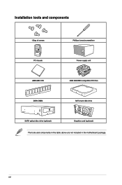
xvi Installation tools and components 1 Bag of screws Phillips (cross) screwdriver PC chassis Power supply unit AMD AM4 CPU AMD AM4/AM3 compatible CPU Fan DDR4 DIMM SATA hard disk drive SATA optical disc drive (optional) Graphics card (optional) The tools and components in the table above are not included in the motherboard package.
xvi Installation tools and components 1 Bag of screws Phillips (cross) screwdriver PC chassis Power supply unit AMD AM4 CPU AMD AM4/AM3 compatible CPU Fan DDR4 DIMM SATA hard disk drive SATA optical disc drive (optional) Graphics card (optional) The tools and components in the table above are not included in the motherboard package.

Users Manual English
Page 17
ROG CROSSHAIR VII HERO 1-1 Chapter 1 Chapter 1: Product Introduction Product Introduction 1 1.1 Motherboard overview 1.1.1 Before you proceed Take note of the following precautions before you install motherboard components or change any motherboard settings. • Unplug the power cord from the wall socket before touching any ...uninstall any component, place it on a grounded antistatic pad or in the bag that came with the component. • Before you install or remove any component, ensure that the ATX power supply is switched off or the power cord is detached from the power supply...
ROG CROSSHAIR VII HERO 1-1 Chapter 1 Chapter 1: Product Introduction Product Introduction 1 1.1 Motherboard overview 1.1.1 Before you proceed Take note of the following precautions before you install motherboard components or change any motherboard settings. • Unplug the power cord from the wall socket before touching any ...uninstall any component, place it on a grounded antistatic pad or in the bag that came with the component. • Before you install or remove any component, ensure that the ATX power supply is switched off or the power cord is detached from the power supply...
Users Manual English
Page 20
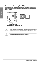
... bending the connectors on the socket and damaging the CPU! The AM4 socket has a different pinout design. Ensure that all power cables are unplugged before installing the CPU. 1-4 Chapter 1: Product Introduction Ensure that you use a CPU designed for AMD Ryzen™ 2nd Generation / Ryzen™ 1st Generation / Ryzen™ with Radeon...
... bending the connectors on the socket and damaging the CPU! The AM4 socket has a different pinout design. Ensure that all power cables are unplugged before installing the CPU. 1-4 Chapter 1: Product Introduction Ensure that you use a CPU designed for AMD Ryzen™ 2nd Generation / Ryzen™ 1st Generation / Ryzen™ with Radeon...
Users Manual English
Page 21
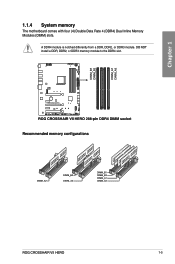
DO NOT install a DDR, DDR2, or DDR3 memory module to the DDR4 slot. Recommended memory configurations ROG CROSSHAIR VII HERO 1-5 Chapter 1 1.1.4 System memory The motherboard comes with four (4) Double Data Rate 4 (DDR4) Dual Inline Memory Modules (DIMM) slots. A DDR4 module is notched differently from a DDR, DDR2, or DDR3 module.
DO NOT install a DDR, DDR2, or DDR3 memory module to the DDR4 slot. Recommended memory configurations ROG CROSSHAIR VII HERO 1-5 Chapter 1 1.1.4 System memory The motherboard comes with four (4) Double Data Rate 4 (DDR4) Dual Inline Memory Modules (DIMM) slots. A DDR4 module is notched differently from a DDR, DDR2, or DDR3 module.
Users Manual English
Page 22
... mapped for the dual-channel configuration. Check with the vendor to support a full memory load (4 DIMMs) or overclocking condition. • Always install the DIMMS with the same CAS Latency. You may operate at a lower frequency than the vendor-marked value. • For system stability, ...same version or data code (D/C) from a memory module. For an optimum compatibility, we recommend that you install memory modules of accessing information from the same vendor. Chapter 1 Memory configurations You may install 2 GB, 4 GB, 8 GB, and 16 GB unbuffered and non‑ECC DDR4 DIMMs into...
... mapped for the dual-channel configuration. Check with the vendor to support a full memory load (4 DIMMs) or overclocking condition. • Always install the DIMMS with the same CAS Latency. You may operate at a lower frequency than the vendor-marked value. • For system stability, ...same version or data code (D/C) from a memory module. For an optimum compatibility, we recommend that you install memory modules of accessing information from the same vendor. Chapter 1 Memory configurations You may install 2 GB, 4 GB, 8 GB, and 16 GB unbuffered and non‑ECC DDR4 DIMMs into...
Users Manual English
Page 25
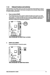
RESET button (RESET) Press the reset button to enhance system performance. 1. ROG CROSSHAIR VII HERO 1-9 This is plugged to fine-tune performance when working on button that allows you should shut down the system and unplug the power cable before removing or installing any motherboard component. 2. Power-on button (START) The motherboard comes with a power-on...
RESET button (RESET) Press the reset button to enhance system performance. 1. ROG CROSSHAIR VII HERO 1-9 This is plugged to fine-tune performance when working on button that allows you should shut down the system and unplug the power cable before removing or installing any motherboard component. 2. Power-on button (START) The motherboard comes with a power-on...
Users Manual English
Page 31
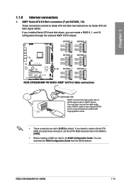
... Configuration Guide. ROG CROSSHAIR VII HERO 1-15 AMD® Serial ATA 6.0 Gb/s connectors (7-pin SATA6G_1-6) These connectors connect to [AHCI] by default. If you can download the RAID Configuration Guide from the ASUS website. 1.1.9 Internal connectors 1. You can create a RAID 0, 1, and 10 configuration through the onboard AMD® X470 chipset. If you installed Serial ATA hard...
... Configuration Guide. ROG CROSSHAIR VII HERO 1-15 AMD® Serial ATA 6.0 Gb/s connectors (7-pin SATA6G_1-6) These connectors connect to [AHCI] by default. If you can download the RAID Configuration Guide from the ASUS website. 1.1.9 Internal connectors 1. You can create a RAID 0, 1, and 10 configuration through the onboard AMD® X470 chipset. If you installed Serial ATA hard...
Users Manual English
Page 32
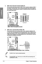
... allows you to 10 Gbps. The USB 3.1 Gen 1 module is completely backward-compatible with USB 2.0. Chapter 1 3. The next-generation standard is purchased separately. 2. With an installed USB 3.1 Gen 1 module, you can enjoy all the benefits of USB 3.1 Gen 1 including faster data transfer speeds of up to connect a USB 3.1 Gen 1 module for...
... allows you to 10 Gbps. The USB 3.1 Gen 1 module is completely backward-compatible with USB 2.0. Chapter 1 3. The next-generation standard is purchased separately. 2. With an installed USB 3.1 Gen 1 module, you can enjoy all the benefits of USB 3.1 Gen 1 including faster data transfer speeds of up to connect a USB 3.1 Gen 1 module for...
Users Manual English
Page 33
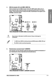
... (2-pin T_SENSOR1) This connector is purchased separately. 5. Connect the USB module cable to any of these connectors, then install the module to 480 MBps connection speed. USB1112) These connectors are for the thermistor cable that allows you to the ...connectors comply with USB 2.0 specification that supports up to a slot opening at mid-board shares with ROG extension (ROG_EXT) port. • The USB 2.0 module is for USB 2.0 ports. USB 2.0 connector (10-1 pin USB15; ROG CROSSHAIR VII HERO 1-17 Chapter 1 4. Doing so will damage the motherboard! • 1 x USB 2.0 ...
... (2-pin T_SENSOR1) This connector is purchased separately. 5. Connect the USB module cable to any of these connectors, then install the module to 480 MBps connection speed. USB1112) These connectors are for the thermistor cable that allows you to the ...connectors comply with USB 2.0 specification that supports up to a slot opening at mid-board shares with ROG extension (ROG_EXT) port. • The USB 2.0 module is for USB 2.0 ports. USB 2.0 connector (10-1 pin USB15; ROG CROSSHAIR VII HERO 1-17 Chapter 1 4. Doing so will damage the motherboard! • 1 x USB 2.0 ...
Users Manual English
Page 35
...forget to connect the fan cables to the CPU_FAN and/or CPU_OPT header(s). • W_PUMP+ function support depends on water cooling device. ROG CROSSHAIR VII HERO 1-19 Do not place jumper caps on the motherboard, ensuring that the black wire of each cable matches the ground pin of the connector... CPU_FAN; 4-pin CPU_OPT; 4-pin H_AMP; 4-pin AIO_PUMP; 4-pin W_PUMP+; 5-pin EXT_FAN; 4-pin CHA_FAN1-3) Connect the fan cables to the To install Fan Extension Card section in -one cooler (AIO cooler) to the AIO_PUMP header, and connect the fan cables to the fan connectors. The EXT_FAN connector...
...forget to connect the fan cables to the CPU_FAN and/or CPU_OPT header(s). • W_PUMP+ function support depends on water cooling device. ROG CROSSHAIR VII HERO 1-19 Do not place jumper caps on the motherboard, ensuring that the black wire of each cable matches the ground pin of the connector... CPU_FAN; 4-pin CPU_OPT; 4-pin H_AMP; 4-pin AIO_PUMP; 4-pin W_PUMP+; 5-pin EXT_FAN; 4-pin CHA_FAN1-3) Connect the fan cables to the To install Fan Extension Card section in -one cooler (AIO cooler) to the AIO_PUMP header, and connect the fan cables to the fan connectors. The EXT_FAN connector...
Users Manual English
Page 38
... is connected in the correct orientation, and the 12V connector is aligned with a maximum power rating of 3A (12V), and no longer than 3 m. Before you install or remove any component, ensure that the ATX power supply is switched off or the power cord is purchased separately. 1-22 Chapter 1: Product Introduction Chapter...
... is connected in the correct orientation, and the 12V connector is aligned with a maximum power rating of 3A (12V), and no longer than 3 m. Before you install or remove any component, ensure that the ATX power supply is switched off or the power cord is purchased separately. 1-22 Chapter 1: Product Introduction Chapter...
Users Manual English
Page 39
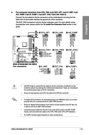
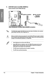
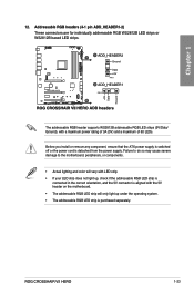
... lighting and color will only light up under the operating system. • The addressable RGB LED strip is detached from the power supply. Before you install or remove any component, ensure that the ATX power supply is switched off or the power cord is purchased separately. Chapter 1 The addressable RGB header... a maximum of 60 LEDs. Addressable RGB headers (4-1 pin ADD_HEADER1-2) These connectors are for individually addressable RGB WS2812B LED strips or WS2812B based LED strips. 12. ROG CROSSHAIR VII HERO 1-23
... lighting and color will only light up under the operating system. • The addressable RGB LED strip is detached from the power supply. Before you install or remove any component, ensure that the ATX power supply is switched off or the power cord is purchased separately. Chapter 1 The addressable RGB header... a maximum of 60 LEDs. Addressable RGB headers (4-1 pin ADD_HEADER1-2) These connectors are for individually addressable RGB WS2812B LED strips or WS2812B based LED strips. 12. ROG CROSSHAIR VII HERO 1-23
Users Manual English
Page 41
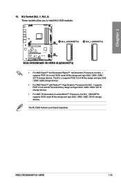
ROG CROSSHAIR VII HERO 1-25 M.2_2) These sockets allow you to install M.2 SSD modules. • For AMD Ryzen™ 2nd Generation/Ryzen™ 1st Generation Processors, the M.2_1 supports PCIE 3.0 x4 and SATA mode M Key design and ...
ROG CROSSHAIR VII HERO 1-25 M.2_2) These sockets allow you to install M.2 SSD modules. • For AMD Ryzen™ 2nd Generation/Ryzen™ 1st Generation Processors, the M.2_1 supports PCIE 3.0 x4 and SATA mode M Key design and ...
Users Manual English
Page 43
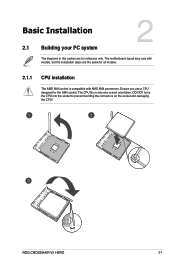
The CPU fits in this section are the same for the AM4 socket. Chapter 2 ROG CROSSHAIR VII HERO 2-1 Ensure you use a CPU designed for all models. 2.1.1 CPU installation The AMD AM4 socket is compatible with AMD AM4 processors. The motherboard layout may vary with models, but the installation steps are for reference only. DO NOT force the CPU into the socket to prevent bending the connectors on the socket and damaging the CPU! Chapter 2: Basic Installation Basic Installation 2.1 Building your PC system 2 The diagrams in only one correct orientation.
The CPU fits in this section are the same for the AM4 socket. Chapter 2 ROG CROSSHAIR VII HERO 2-1 Ensure you use a CPU designed for all models. 2.1.1 CPU installation The AMD AM4 socket is compatible with AMD AM4 processors. The motherboard layout may vary with models, but the installation steps are for reference only. DO NOT force the CPU into the socket to prevent bending the connectors on the socket and damaging the CPU! Chapter 2: Basic Installation Basic Installation 2.1 Building your PC system 2 The diagrams in only one correct orientation.
Users Manual English
Page 44
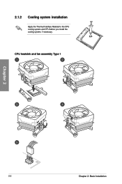
2.1.2 Cooling system installation Apply the Thermal Interface Material to the CPU cooling system and CPU before you install the cooling system, if necessary. CPU heatsink and fan assembly Type 1 Chapter 2 2-2 Chapter 2: Basic Installation
2.1.2 Cooling system installation Apply the Thermal Interface Material to the CPU cooling system and CPU before you install the cooling system, if necessary. CPU heatsink and fan assembly Type 1 Chapter 2 2-2 Chapter 2: Basic Installation
Users Manual English
Page 47
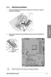
Place the motherboard into the holes indicated by circles to secure the motherboard to the chassis' rear I/O panel. 2. Chapter 2 DO NOT over tighten the screws! Place nine (9) screws into the chassis, ensuring that its rear I/O ports are aligned to the chassis. ROG CROSSHAIR VII HERO 2-5 2.1.3 Motherboard installation 1. Doing so can damage the motherboard.
Place the motherboard into the holes indicated by circles to secure the motherboard to the chassis' rear I/O panel. 2. Chapter 2 DO NOT over tighten the screws! Place nine (9) screws into the chassis, ensuring that its rear I/O ports are aligned to the chassis. ROG CROSSHAIR VII HERO 2-5 2.1.3 Motherboard installation 1. Doing so can damage the motherboard.
Users Manual English
Page 48
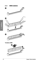
2.1.4 DIMM installation Chapter 2 To remove a DIMM 2-6 Chapter 2: Basic Installation
2.1.4 DIMM installation Chapter 2 To remove a DIMM 2-6 Chapter 2: Basic Installation


