
User Guide
Page 3
... information vii About this guide viii RAMPAGE V EXTREME specifications summary OC Panel specifications summary xv Package contents xvi Installation tools and components xvii Chapter 1: Product Introduction 1.1 Special features 1-1 1.1.1 Product highlights 1-1 1.1.2 ROG Unique Gaming Features 1-2 1.1.3 ROG exclusive features 1-3 1.1.4 ASUS special features 1-5 1.1.5 ROG rich-bundled software 1-6 1.2 Motherboard overview 1-7 1.2.1 Before you proceed 1-7 1.2.2 Motherboard layout 1-8 1.2.3 Central Processing Unit (CPU...
... information vii About this guide viii RAMPAGE V EXTREME specifications summary OC Panel specifications summary xv Package contents xvi Installation tools and components xvii Chapter 1: Product Introduction 1.1 Special features 1-1 1.1.1 Product highlights 1-1 1.1.2 ROG Unique Gaming Features 1-2 1.1.3 ROG exclusive features 1-3 1.1.4 ASUS special features 1-5 1.1.5 ROG rich-bundled software 1-6 1.2 Motherboard overview 1-7 1.2.1 Before you proceed 1-7 1.2.2 Motherboard layout 1-8 1.2.3 Central Processing Unit (CPU...
User Guide
Page 15
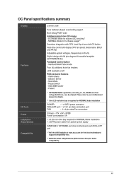
...usage** Seamless integration with 90 plus-degree-tilt movable faceplate (EXTREME Mode) FanSpeed Control button - $tandard/Silent/Turto mode Four (4) additional 4-pin fan headers LCM backlight on -the-fly Stylish design with CPU Level Up at www.asus.com for the latest motherboard support/compatibility lists. ** Install the latest utility/firmware (ROG...connectors Voltage: +12V, +5V, +5VSB Power consumption: 5A 1 x 5.25-inch drive bay required for NORMAL Mode installation 1 x SATA power cable from system power supply RAMPAGE V EXTREME and other voltage definitions, vary by chipset.
...usage** Seamless integration with 90 plus-degree-tilt movable faceplate (EXTREME Mode) FanSpeed Control button - $tandard/Silent/Turto mode Four (4) additional 4-pin fan headers LCM backlight on -the-fly Stylish design with CPU Level Up at www.asus.com for the latest motherboard support/compatibility lists. ** Install the latest utility/firmware (ROG...connectors Voltage: +12V, +5V, +5VSB Power consumption: 5A 1 x 5.25-inch drive bay required for NORMAL Mode installation 1 x SATA power cable from system power supply RAMPAGE V EXTREME and other voltage definitions, vary by chipset.
User Guide
Page 16
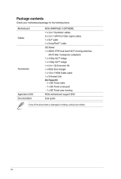
Package contents Check your motherboard package for the following items. Motherboard Cables Accessories Application DVD Documentation ROG RAMPAGE V EXTREME 1 x 3-in-1 thermistor cables 5 x 2-in-1 SATA 6.0 Gb/s signal cables 1 x SLI® cable 1 x CrossFireXJM cable I/O Shield 1 x ASUS 3T3R dual band Wi-Fi moving antennas (Wi-Fi 802.11a/b/g/n/ac compliant) 1 x 3-Way SLITM bridge 1 x 4-Way SLITM bridge 1 x 2-in-1 Q-Connector Kit...
Package contents Check your motherboard package for the following items. Motherboard Cables Accessories Application DVD Documentation ROG RAMPAGE V EXTREME 1 x 3-in-1 thermistor cables 5 x 2-in-1 SATA 6.0 Gb/s signal cables 1 x SLI® cable 1 x CrossFireXJM cable I/O Shield 1 x ASUS 3T3R dual band Wi-Fi moving antennas (Wi-Fi 802.11a/b/g/n/ac compliant) 1 x 3-Way SLITM bridge 1 x 4-Way SLITM bridge 1 x 2-in-1 Q-Connector Kit...
User Guide
Page 19
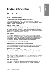
...Goren" i7 processors. It also enables the iGPU function for updated details. 3-Way/4-way/Quad-GPU SLITM and CrossFireXTM Support This motherboard features Intel's powerful new X99 platform and optimizes PCIe allocation in the LGA2011-v3 package. PCIe 3.0 provides you the ultimate gaming...performance. It also features backward compatibility with the speed of the SSDs. Functions are available when using PCie 3.0-compliant devices. ASUS RAMPAGE V EXTREME 1-1 SATA Express support SATA Express provides faster data transfer speeds of up to 10 Gb/s allowing your OS and apps ...
...Goren" i7 processors. It also enables the iGPU function for updated details. 3-Way/4-way/Quad-GPU SLITM and CrossFireXTM Support This motherboard features Intel's powerful new X99 platform and optimizes PCIe allocation in the LGA2011-v3 package. PCIe 3.0 provides you the ultimate gaming...performance. It also features backward compatibility with the speed of the SSDs. Functions are available when using PCie 3.0-compliant devices. ASUS RAMPAGE V EXTREME 1-1 SATA Express support SATA Express provides faster data transfer speeds of up to 10 Gb/s allowing your OS and apps ...
User Guide
Page 21
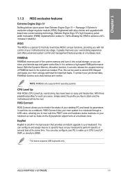
... POST code and hardware status readouts on your notebook as well as needed. This feature supports USB keyboards only. Rampage V Extreme's exclusive voltage-regulator module (VRM). ASUS RAMPAGE V EXTREME 1-3 It greatly improves your keyboard. To protect your motherboard at a hardware level. ROG Connect ROG Connect allows you to the system as make on your keyboard to...
... POST code and hardware status readouts on your notebook as well as needed. This feature supports USB keyboards only. Rampage V Extreme's exclusive voltage-regulator module (VRM). ASUS RAMPAGE V EXTREME 1-3 It greatly improves your keyboard. To protect your motherboard at a hardware level. ROG Connect ROG Connect allows you to the system as make on your keyboard to...
User Guide
Page 25
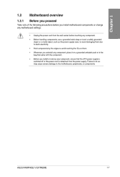
... grounded antistatic pad or in the bag that came with the component. • Before you install motherboard components or change any component, ensure that the ATX power supply is switched off or the power cord... is detached from the wall socket before you install or remove any motherboard settings. 1.2 Motherboard overview 1.2.1 Before you proceed IcLu Take note of the following precautions before touching any component. &#...electricity. • Hold components by the edges to the motherboard, peripherals, or components. ASUS RAMPAGE V EXTREME 1-7
... grounded antistatic pad or in the bag that came with the component. • Before you install motherboard components or change any component, ensure that the ATX power supply is switched off or the power cord... is detached from the wall socket before you install or remove any motherboard settings. 1.2 Motherboard overview 1.2.1 Before you proceed IcLu Take note of the following precautions before touching any component. &#...electricity. • Hold components by the edges to the motherboard, peripherals, or components. ASUS RAMPAGE V EXTREME 1-7
User Guide
Page 28
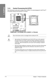
...transit-related. • Keep the cap after installing the motherboard. RD '1::1:1' 0 AMC I=C 0 w I 'DO L ED uu Eno LEEEEnfo°591M__ImmEmEol =not RAMPAGE V EXTREME CPU LGA2011-v3 Socket Ensure that the PnP cap is missing..., or if you see any damage to the socket contacts resulting from incorrect CPU installation/removal, or misplacement/loss/incorrect removal of the PnP cap. 1-10 Chapter 1: Product introduction ASUS will process Return Merchandise Authorization (RMA) requests only if the motherboard...
...transit-related. • Keep the cap after installing the motherboard. RD '1::1:1' 0 AMC I=C 0 w I 'DO L ED uu Eno LEEEEnfo°591M__ImmEmEol =not RAMPAGE V EXTREME CPU LGA2011-v3 Socket Ensure that the PnP cap is missing..., or if you see any damage to the socket contacts resulting from incorrect CPU installation/removal, or misplacement/loss/incorrect removal of the PnP cap. 1-10 Chapter 1: Product introduction ASUS will process Return Merchandise Authorization (RMA) requests only if the motherboard...
User Guide
Page 29
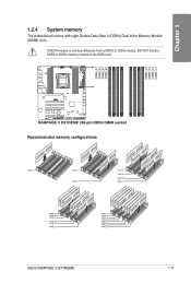
... DIMALC1 z DIMM_A1 DIMM_A2 DIMM_B1 DIMM_D2 DIMNLD1 DIMM_C1 • ~ ~`/~~ DIMM_A1 DIMM_B1 DIMMJ)1 DIMM_C1 DEG DIMM_A1 DIMM_A2 DIMI D1 DIMMJE12 DIMILD2 DIMILD1 DIMILC2 DIMM_C1 O oo ASUS RAMPAGE V EXTREME 1-11 1.2.4 System memory The motherboard comes with eight Double Data Rate 4 (DDR4) Dual Inline Memory Module CO (DIMM) slots. al l col I 2 2 2 2 mmmm 5636 CSI a a MIMI2 I 2222 6666 ci...
... DIMALC1 z DIMM_A1 DIMM_A2 DIMM_B1 DIMM_D2 DIMNLD1 DIMM_C1 • ~ ~`/~~ DIMM_A1 DIMM_B1 DIMMJ)1 DIMM_C1 DEG DIMM_A1 DIMM_A2 DIMI D1 DIMMJE12 DIMILD2 DIMILD1 DIMILC2 DIMM_C1 O oo ASUS RAMPAGE V EXTREME 1-11 1.2.4 System memory The motherboard comes with eight Double Data Rate 4 (DDR4) Dual Inline Memory Module CO (DIMM) slots. al l col I 2 2 2 2 mmmm 5636 CSI a a MIMI2 I 2222 6666 ci...
User Guide
Page 31
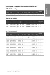
...; • 17-18-18-35 1.2V • • 17-18-18-35 1.2V • • ASUS RAMPAGE V EXTREME 1-13 Size F4-3000C16O-16GRR 16GB ( 4x SS 4GB) F4-3000C16O-32GRR 32GB ( 4x DS 8GB) Chlp Brand Chlp NO. RAMPAGE V EXTREME Motherboard Qualified Vendors List (QVL) DDR4 3300 MHz capability Vendors Part No. Chip NO. G.SKILL F4...
...; • 17-18-18-35 1.2V • • 17-18-18-35 1.2V • • ASUS RAMPAGE V EXTREME 1-13 Size F4-3000C16O-16GRR 16GB ( 4x SS 4GB) F4-3000C16O-32GRR 32GB ( 4x DS 8GB) Chlp Brand Chlp NO. RAMPAGE V EXTREME Motherboard Qualified Vendors List (QVL) DDR4 3300 MHz capability Vendors Part No. Chip NO. G.SKILL F4...
User Guide
Page 39
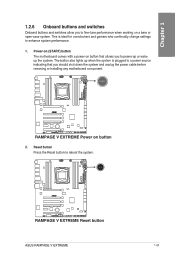
... V EXTREMI I7 O EOJ Z = IZ -flJ1=1=CallaLLO =IA RAMPAGE V EXTREME Power on button that you should shut down the system and unplug the power cable before removing or installing any motherboard component. Reset button Press the Reset button to fine-tune performance when...) button The motherboard comes with a power-on button 2. 1.2.6 Onboard buttons and switches Onboard buttons and switches allow you to reboot the system. • Die 7 RillAPiNiff V KXTFINIMI i7,0 LEE De LEonoio=aeil r-r-IrDro mom =Et RAMPAGE V EXTREME Reset button ASUS RAMPAGE V EXTREME 1-21 The ...
... V EXTREMI I7 O EOJ Z = IZ -flJ1=1=CallaLLO =IA RAMPAGE V EXTREME Power on button that you should shut down the system and unplug the power cable before removing or installing any motherboard component. Reset button Press the Reset button to fine-tune performance when...) button The motherboard comes with a power-on button 2. 1.2.6 Onboard buttons and switches Onboard buttons and switches allow you to reboot the system. • Die 7 RillAPiNiff V KXTFINIMI i7,0 LEE De LEonoio=aeil r-r-IrDro mom =Et RAMPAGE V EXTREME Reset button ASUS RAMPAGE V EXTREME 1-21 The ...
User Guide
Page 40
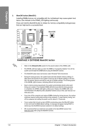
...motherboard may cause system boot failure. A message will appear during the tuning process, the system continues memory tuning after using the MemOKI function. • The MemOK! button (MemOK!) Installing DIMMs that can help lead to BIOS overclocking, press the MemOK! via IzQ , Eun MOW% V EXITIEWIZC Da ito ,I nami:o=olia=mrarommo anatook, RAMPAGE V EXTREME... are not compatible with ones recommended in the Memory QVL (Qualified Vendors Lists) in this user manual or at www.asus.com. • If you download and update to boot and load the BIOS default settings. If the installed DIMMs...
...motherboard may cause system boot failure. A message will appear during the tuning process, the system continues memory tuning after using the MemOKI function. • The MemOK! button (MemOK!) Installing DIMMs that can help lead to BIOS overclocking, press the MemOK! via IzQ , Eun MOW% V EXITIEWIZC Da ito ,I nami:o=olia=mrarommo anatook, RAMPAGE V EXTREME... are not compatible with ones recommended in the Memory QVL (Qualified Vendors Lists) in this user manual or at www.asus.com. • If you download and update to boot and load the BIOS default settings. If the installed DIMMs...
User Guide
Page 41
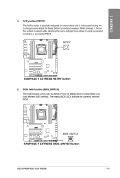
... quick succession U to switch BIOS and load different BIOS settings. RETRY lz.] ,,..... -I 7 I I7O L E o Ogilt Ca= ii BIOS_SWITCH 2k 0. 0 T' PI • • RAMPAGE V EXTREME BIOS_SWITCH button ASUS RAMPAGE V EXTREME 1-23 BIOS Switch button (BIOS_SWITCH) The motherboard comes with two BIOS. Press the BIOS button to achieve a successful POST. The nearby BIOS LEDs indicate the currently selected BIOS...
... quick succession U to switch BIOS and load different BIOS settings. RETRY lz.] ,,..... -I 7 I I7O L E o Ogilt Ca= ii BIOS_SWITCH 2k 0. 0 T' PI • • RAMPAGE V EXTREME BIOS_SWITCH button ASUS RAMPAGE V EXTREME 1-23 BIOS Switch button (BIOS_SWITCH) The motherboard comes with two BIOS. Press the BIOS button to achieve a successful POST. The nearby BIOS LEDs indicate the currently selected BIOS...
User Guide
Page 46
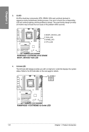
...BOOT_DEVICE_LED I 0 VGA_LED 0 DRAM_LED ❑° CPU_LED CI I H co o RAMPAGE V EXTREME CPU/ DRAM/ BOOT_DEVICE/ VGA LED 4. CODE1 u /sus u RAMPAGE V EXTREME Q-Code LED 1-28 Chapter 1: Product introduction If an error is found, the ...corresponding LED will continue lighting until the problem is solved. Refer to locate the root-cause of the problem within seconds. Q LED Q LEDs check key components (CPU, DRAM, VGA card, and boot devices) in sequence during motherboard...
...BOOT_DEVICE_LED I 0 VGA_LED 0 DRAM_LED ❑° CPU_LED CI I H co o RAMPAGE V EXTREME CPU/ DRAM/ BOOT_DEVICE/ VGA LED 4. CODE1 u /sus u RAMPAGE V EXTREME Q-Code LED 1-28 Chapter 1: Product introduction If an error is found, the ...corresponding LED will continue lighting until the problem is solved. Refer to locate the root-cause of the problem within seconds. Q LED Q LEDs check key components (CPU, DRAM, VGA card, and boot devices) in sequence during motherboard...
User Guide
Page 52
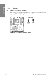
LN2 Mode jumper (3-pin LN2_MODE) With LN2 mode activated, the ROG motherboard is optimized to remedy the cold-boot bug during POST and help the system boot successfully. C1M : ° . ca.= mul RAMPAGE V EXTREME LN2_MODE setting 1-34 Chapter 1: Product introduction E LN2_MODE 0 2 • 1 • Disable (Default) 3 2 0 Enable 7_J /ELM ff.__I .__I ff.__I 7C) L° ° Cr, E ® '=unolf.0. 1.2.8 Jumper 1.
LN2 Mode jumper (3-pin LN2_MODE) With LN2 mode activated, the ROG motherboard is optimized to remedy the cold-boot bug during POST and help the system boot successfully. C1M : ° . ca.= mul RAMPAGE V EXTREME LN2_MODE setting 1-34 Chapter 1: Product introduction E LN2_MODE 0 2 • 1 • Disable (Default) 3 2 0 Enable 7_J /ELM ff.__I .__I ff.__I 7C) L° ° Cr, E ® '=unolf.0. 1.2.8 Jumper 1.
User Guide
Page 53
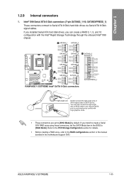
... can create a RAID 0, 1, 5, and 10 configuration with huge graphics cards. • These connectors are set the SATA Mode item in the motherboard support DVD. If you installed Serial ATA hard disk drives, you intend to create a Serial ATA RAID array using these connectors, set to [AHCI... D C) ®opt:i L❑ Ert =mot OM FISATA_MS RSATA_TXNII OND IISATAJIXN0 PAGIAJGO29 OND OND FISATA_TXPIO IISMA_TXN10 GND PSATUTOGO GSATAPX1.10 OND - RAMPAGE V EXTREME Intel® SATA 6 Gb/s connectors SATA6G_5 SATA6G_6 OND IIGATA_TXP5 RSAGUIENS GNG FIGOTA_MG. ASUS RAMPAGE V EXTREME 1-35
... can create a RAID 0, 1, 5, and 10 configuration with huge graphics cards. • These connectors are set the SATA Mode item in the motherboard support DVD. If you installed Serial ATA hard disk drives, you intend to create a Serial ATA RAID array using these connectors, set to [AHCI... D C) ®opt:i L❑ Ert =mot OM FISATA_MS RSATA_TXNII OND IISATAJIXN0 PAGIAJGO29 OND OND FISATA_TXPIO IISMA_TXN10 GND PSATUTOGO GSATAPX1.10 OND - RAMPAGE V EXTREME Intel® SATA 6 Gb/s connectors SATA6G_5 SATA6G_6 OND IIGATA_TXP5 RSAGUIENS GNG FIGOTA_MG. ASUS RAMPAGE V EXTREME 1-35
User Guide
Page 56
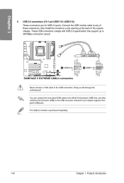
... cable to the ASUS Q-Connector (USB) first, and then install the Q-Connector (USB) to 480 Mbps connection speed. 1E= 0 f= 0 0 /NM O ,c) Lu Er OUSB1314 PIN 1 - 1 - 1 . Ptg RAMPAGE V EXTREME USB2.0 connectors zo OUSB1112 PIN 1 Never connect a 1394 cable to a slot opening at the back of the system chassis. Doing so will damage the motherboard! USB1314) r-F These...
... cable to the ASUS Q-Connector (USB) first, and then install the Q-Connector (USB) to 480 Mbps connection speed. 1E= 0 f= 0 0 /NM O ,c) Lu Er OUSB1314 PIN 1 - 1 - 1 . Ptg RAMPAGE V EXTREME USB2.0 connectors zo OUSB1112 PIN 1 Never connect a 1394 cable to a slot opening at the back of the system chassis. Doing so will damage the motherboard! USB1314) r-F These...
User Guide
Page 57
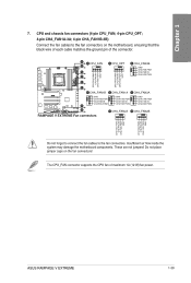
...) fan power. Insufficient air flow inside the system may damage the motherboard components. Do not place jumper caps on the motherboard, ensuring that the to the fan connectors. These are not jumpers! The CPU_FAN connector supports the CPU fan of the connector. ASUS RAMPAGE V EXTREME 1-39 s-i 7. CPU and chassis fan connectors (4-pin CPU_FAN; 4-pin CPU_0PT...
...) fan power. Insufficient air flow inside the system may damage the motherboard components. Do not place jumper caps on the motherboard, ensuring that the to the fan connectors. These are not jumpers! The CPU_FAN connector supports the CPU fan of the connector. ASUS RAMPAGE V EXTREME 1-39 s-i 7. CPU and chassis fan connectors (4-pin CPU_FAN; 4-pin CPU_0PT...
User Guide
Page 58
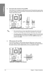
...HD-audio-compliant Legacy AC'97 pin definition compliant definition RAMPAGE V EXTREME Analog front panel connector • We recommend that supports either HD Audio or legacy AC'97 audio standard. Connect one end of the motherboard's high-definition audio capability. • If you want... this connector. E u MP= u CJ • • • Eg c2H,A, TPM zcls:Lk, (z73e:5 ,.Zz m •=• RAMPAGE V EXTREME TPM connector 1-40 Chapter 1: Product introduction Front panel audio connector (10-1 pin AAFP) This connector is set the item to take advantage of the front...
...HD-audio-compliant Legacy AC'97 pin definition compliant definition RAMPAGE V EXTREME Analog front panel connector • We recommend that supports either HD Audio or legacy AC'97 audio standard. Connect one end of the motherboard's high-definition audio capability. • If you want... this connector. E u MP= u CJ • • • Eg c2H,A, TPM zcls:Lk, (z73e:5 ,.Zz m •=• RAMPAGE V EXTREME TPM connector 1-40 Chapter 1: Product introduction Front panel audio connector (10-1 pin AAFP) This connector is set the item to take advantage of the front...

User Guide
Page 63
...RAM_AB ▪ RAM_CD ▪ PCH ▪ PCHJO un u RAMPAGE V EXTREME Probelt Using Probelt You can connect the multimeter to measure the Probelt points even during overclocking. ASUS RAMPAGE V EXTREME 1-45 Use a co multimeter to the motherboard as shown on the following figure. 0 CD 0 00 The... illustration above are for reference only, the actual motherboard layout and measure points location may differ ...
...RAM_AB ▪ RAM_CD ▪ PCH ▪ PCHJO un u RAMPAGE V EXTREME Probelt Using Probelt You can connect the multimeter to measure the Probelt points even during overclocking. ASUS RAMPAGE V EXTREME 1-45 Use a co multimeter to the motherboard as shown on the following figure. 0 CD 0 00 The... illustration above are for reference only, the actual motherboard layout and measure points location may differ ...
User Guide
Page 65
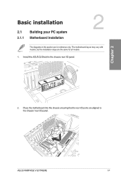
tosogsosoossso9, c oo 8 a CD 2. Basic installation 2.1 2.1.1 Building your PC system Motherboard installation The diagrams in this section are the same for reference only. The motherboard layout may vary with N models, but the installation steps are for all models. +CaT, 1. Install the ASUS Q-Shield to the chassis' rear I /O panel. Place the motherboard into the chassis ensuring that its rear I/O ports are aligned to the chassis rear I /O panel. ASUS RAMPAGE V EXTREME 2-1 a 10 U o k7a0o0g700,o0,og,,00,00g40no0olLi60oOo000i0.
tosogsosoossso9, c oo 8 a CD 2. Basic installation 2.1 2.1.1 Building your PC system Motherboard installation The diagrams in this section are the same for reference only. The motherboard layout may vary with N models, but the installation steps are for all models. +CaT, 1. Install the ASUS Q-Shield to the chassis' rear I /O panel. Place the motherboard into the chassis ensuring that its rear I/O ports are aligned to the chassis rear I /O panel. ASUS RAMPAGE V EXTREME 2-1 a 10 U o k7a0o0g700,o0,og,,00,00g40no0olLi60oOo000i0.


