User Manual
Page 20
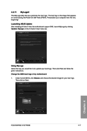
... desired image for your computer from the motherboard support DVD, launch MyLogo by clicking Update> MyLogo on the AI Suite II main menu bar. Launching ASUS Update After installing AI Suite II from the very beginning! Personalize your boot logo. The boot logo is the image that appears on Next. 20...
... desired image for your computer from the motherboard support DVD, launch MyLogo by clicking Update> MyLogo on the AI Suite II main menu bar. Launching ASUS Update After installing AI Suite II from the very beginning! Personalize your boot logo. The boot logo is the image that appears on Next. 20...
User Manual
Page 16
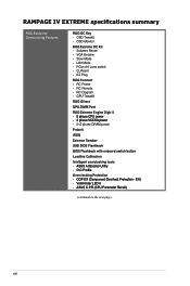
... - LN2 Mode - RC Poster - RC Remote - RAMPAGE IV EXTREME specifications summary ROG Exclusive Overclocking Features ROG OC Key - Subzero Sense - VGA Hotwire - Q_Reset - EZ Plug ROG Connect - RC Diagram - Slow Mode - PCIe x16 Lane switch - OSD Monitor ROG Extreme OC Kit - GPU TweakIt ROG iDirect GPU.DIMM Post ROG Extreme Engine Digi+ II - �8��...
... - LN2 Mode - RC Poster - RC Remote - RAMPAGE IV EXTREME specifications summary ROG Exclusive Overclocking Features ROG OC Key - Subzero Sense - VGA Hotwire - Q_Reset - EZ Plug ROG Connect - RC Diagram - Slow Mode - PCIe x16 Lane switch - OSD Monitor ROG Extreme OC Kit - GPU TweakIt ROG iDirect GPU.DIMM Post ROG Extreme Engine Digi+ II - �8��...
User Manual
Page 21
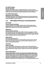
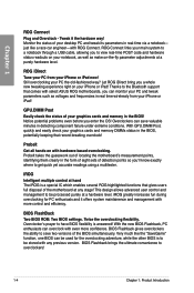
..., taking your system to view POST codes in real-time, complete hardware status and even the readout from VGA Hotwire and Subzero Sense, all at 4.8Gbps with a convenient graphical overlay displayed right on -the-fly. True SATA 6.0 Gb/s Support Experience the Future of 105°C) ROG RAMPAGE IV EXTREME 1-3 VGA Hotwire Hotwire your system...
..., taking your system to view POST codes in real-time, complete hardware status and even the readout from VGA Hotwire and Subzero Sense, all at 4.8Gbps with a convenient graphical overlay displayed right on -the-fly. True SATA 6.0 Gb/s Support Experience the Future of 105°C) ROG RAMPAGE IV EXTREME 1-3 VGA Hotwire Hotwire your system...
User Manual
Page 22
... design allows advanced user control and management to be processed purely at a purely hardware level. Very much like a race car engineer-with select ASUS ROG motherboards, you 'll know exactly where to overclockers! 1-4 Chapter 1: Product Introduction Chapter 1 ROG Connect Plug and Overclock - Monitor the status...! ROG iDirect Tune your PC from your notebook, as well as voltages and frequencies in detecting component failure under extreme conditions. Let ROG iDirect bring you enter the OS! With GPU.DIMM Post, quickly and easily check your iPhone or iPad!
... design allows advanced user control and management to be processed purely at a purely hardware level. Very much like a race car engineer-with select ASUS ROG motherboards, you 'll know exactly where to overclockers! 1-4 Chapter 1: Product Introduction Chapter 1 ROG Connect Plug and Overclock - Monitor the status...! ROG iDirect Tune your PC from your notebook, as well as voltages and frequencies in detecting component failure under extreme conditions. Let ROG iDirect bring you enter the OS! With GPU.DIMM Post, quickly and easily check your iPhone or iPad!
User Manual
Page 43
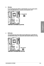
Chapter 2 ROG RAMPAGE IV EXTREME 2-19 GO button Press the GO button before POST to switch BIOS and load different BIOS settings. BIOS button The motherboard comes with two BIOS. Press the BIOS button to enable MemOK! The nearby BIOS LEDs indicate the BIOS you are using. or press it to quickly load the preset profile (GO_Button file) for temporary overclocking when in OS. 4. 3.
Chapter 2 ROG RAMPAGE IV EXTREME 2-19 GO button Press the GO button before POST to switch BIOS and load different BIOS settings. BIOS button The motherboard comes with two BIOS. Press the BIOS button to enable MemOK! The nearby BIOS LEDs indicate the BIOS you are using. or press it to quickly load the preset profile (GO_Button file) for temporary overclocking when in OS. 4. 3.
User Manual
Page 46
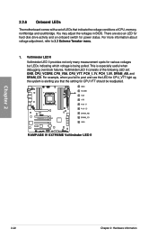
... Voltiminder LED II provides not only many measurement spots for CPU_VTT light up, the system is alerting you fail to 3.3 Extreme Tweaker menu. 1. For more information about voltage adjustment, refer to post and see the LED for various voltages but LEDs indicating which voltage is especially useful when debugging overclock failures. For...
... Voltiminder LED II provides not only many measurement spots for CPU_VTT light up, the system is alerting you fail to 3.3 Extreme Tweaker menu. 1. For more information about voltage adjustment, refer to post and see the LED for various voltages but LEDs indicating which voltage is especially useful when debugging overclock failures. For...

User Manual
Page 48
Chapter 2 2-24 Chapter 2: Hardware information Lighting: Indicates that MemOK! Q LED Q LEDs check key components (CPU, DRAM, VGA card, and booting devices) in OS. 5. If an error is found , the corresponding LED will continue lighting until the problem is enabled before POST. This user-friendly design provides an intuitional way to locate the root problem within a second. 4. is solved. GO LED Blinking: Indicates that the system loads the preset profile (GO_Button file) for temporary overclocking when in sequence during motherboard booting process.
Chapter 2 2-24 Chapter 2: Hardware information Lighting: Indicates that MemOK! Q LED Q LEDs check key components (CPU, DRAM, VGA card, and booting devices) in OS. 5. If an error is found , the corresponding LED will continue lighting until the problem is enabled before POST. This user-friendly design provides an intuitional way to locate the root problem within a second. 4. is solved. GO LED Blinking: Indicates that the system loads the preset profile (GO_Button file) for temporary overclocking when in sequence during motherboard booting process.

User Manual
Page 50
... Pre-memory PCH initialization is started OEM pre-memory initialization codes Memory initialization Reserved for ASL (see ASL Status Codes section below) Memory Installed CPU post-memory initialization Post-Memory System Agent initialization is started 2-26 Chapter 2: Hardware information Reset type detection (soft/hard).
... Pre-memory PCH initialization is started OEM pre-memory initialization codes Memory initialization Reserved for ASL (see ASL Status Codes section below) Memory Installed CPU post-memory initialization Post-Memory System Agent initialization is started 2-26 Chapter 2: Hardware information Reset type detection (soft/hard).

User Manual
Page 51
... Agent module specific) PCH DXE initialization is started ROG RAMPAGE IV EXTREME 2-27 EF F0 F1 F2 F3 F4 F5-F7 F8 F9 FA FB-FF 60 61 62 63 - 67 68 69 6A 6B - 6F 70 Description Post-Memory PCH initialization is started OEM post memory initialization codes DXE IPL is started Memory initialization...
... Agent module specific) PCH DXE initialization is started ROG RAMPAGE IV EXTREME 2-27 EF F0 F1 F2 F3 F4 F5-F7 F8 F9 FA FB-FF 60 61 62 63 - 67 68 69 6A 6B - 6F 70 Description Post-Memory PCH initialization is started OEM post memory initialization codes DXE IPL is started Memory initialization...

User Manual
Page 54
Chapter 2 2-30 Chapter 2: Hardware information OT header (ROG Connect switch) The OT header allows connection of a 2-pin cable switch (purchased separately) for users to remedy the coldboot bug during POST at an extremely low temperature and help the system boot successfully. 2. 2.2.7 Jumper 1. LN2 Mode Jumper (3-pin LN2) With LN2 mode activated, the ROG motherboard is optimized to quickly enable/disable the OC Key feature without using the ROG Connect On/Off button on the rear I/O port.
Chapter 2 2-30 Chapter 2: Hardware information OT header (ROG Connect switch) The OT header allows connection of a 2-pin cable switch (purchased separately) for users to remedy the coldboot bug during POST at an extremely low temperature and help the system boot successfully. 2. 2.2.7 Jumper 1. LN2 Mode Jumper (3-pin LN2) With LN2 mode activated, the ROG motherboard is optimized to quickly enable/disable the OC Key feature without using the ROG Connect On/Off button on the rear I/O port.
User Manual
Page 85
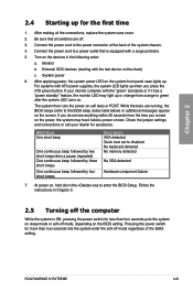
... beep followed by four short beeps Description VGA detected Quick boot set to the BIOS beep codes table below) or additional messages appear on . ROG RAMPAGE IV EXTREME 2-61 Turn on the devices in Chapter 3. 2.5 Turning off the computer While the system is equipped with the "green" standards or if it has a "power... with the last device on the system front panel case lights up for assistance. While the tests are off. 3. At power on self tests or POST.
... beep followed by four short beeps Description VGA detected Quick boot set to the BIOS beep codes table below) or additional messages appear on . ROG RAMPAGE IV EXTREME 2-61 Turn on the devices in Chapter 3. 2.5 Turning off the computer While the system is equipped with the "green" standards or if it has a "power... with the last device on the system front panel case lights up for assistance. While the tests are off. 3. At power on self tests or POST.
User Manual
Page 87
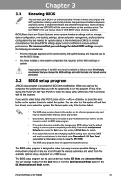
... 3.2 BIOS setup program A BIOS setup program is provided for BIOS item modification. Chapter 3 Chapter 3: 3.1 Knowing BIOS BIOS setup The new ASUS UEFI BIOS is an Unified Extensible Firmware Interface that complies with the help of the BIOS may not exactly match what you see on your... Power-On Self-Test (POST) to restart the system. We recommend that requires further BIOS settings or update. Being a menu-driven program, it back on how to run this section are needed for system startup in the motherboard CMOS. Chapter 3 ROG RAMPAGE IV EXTREME 3-1 BIOS (Basic Input and...
... 3.2 BIOS setup program A BIOS setup program is provided for BIOS item modification. Chapter 3 Chapter 3: 3.1 Knowing BIOS BIOS setup The new ASUS UEFI BIOS is an Unified Extensible Firmware Interface that complies with the help of the BIOS may not exactly match what you see on your... Power-On Self-Test (POST) to restart the system. We recommend that requires further BIOS settings or update. Being a menu-driven program, it back on how to run this section are needed for system startup in the motherboard CMOS. Chapter 3 ROG RAMPAGE IV EXTREME 3-1 BIOS (Basic Input and...

User Manual
Page 100
... to set a fixed CPU voltage. [Offset Mode] Allows you to view the information of installed DIMMs. Extreme OV [Disable] This item is set to [Disabled] by a negative value. GPU/DIMM Post Chapter 3 GPU Post The GPU Post sub-menu allows you to set the Offset voltage. The values range from 0.8000V to 1.7000V with...
... to set a fixed CPU voltage. [Offset Mode] Allows you to view the information of installed DIMMs. Extreme OV [Disable] This item is set to [Disabled] by a negative value. GPU/DIMM Post Chapter 3 GPU Post The GPU Post sub-menu allows you to set the Offset voltage. The values range from 0.8000V to 1.7000V with...

User Manual
Page 112
... you to enabled/disabled the Serial-ATA Controller 1. Chapter 3 3-26 Chapter 3: BIOS setup Serial-ATA Controller 0 [Enabled] Allows you to report warning messages during the POST.
... you to enabled/disabled the Serial-ATA Controller 1. Chapter 3 3-26 Chapter 3: BIOS setup Serial-ATA Controller 0 [Enabled] Allows you to report warning messages during the POST.

User Manual
Page 122
...setup program. The number of device items that appears on the screen depends on the number of devices installed in Safe Mode, press after POST. Click an item to start booting from the available devices. The number of device items that appears on the screen depends on the ...number of devices installed in the system. • To select the boot device during system startup, press when ASUS Logo appears. • To access Windows OS in the system. Boot Override These items displays the available devices. Boot Option Priorities These items specify...
...setup program. The number of device items that appears on the screen depends on the number of devices installed in Safe Mode, press after POST. Click an item to start booting from the available devices. The number of device items that appears on the screen depends on the ...number of devices installed in the system. • To select the boot device during system startup, press when ASUS Logo appears. • To access Windows OS in the system. Boot Override These items displays the available devices. Boot Option Priorities These items specify...
User Manual
Page 129
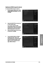
... network traffic. Chapter 3 ROG RAMPAGE IV EXTREME 3-43 If you want to enable the BIOS downgradable function and auto BIOS backup function, check the checkboxs before the two items on screen during the Power‑On Self-Tests (POST). Click Next. 4. From the ASUS Update screen, select Update BIOS from... Internet, and then click Next. 2. You can decide whether to download. Select the ASUS FTP site nearest you want to change the BIOS boot logo,...
... network traffic. Chapter 3 ROG RAMPAGE IV EXTREME 3-43 If you want to enable the BIOS downgradable function and auto BIOS backup function, check the checkboxs before the two items on screen during the Power‑On Self-Tests (POST). Click Next. 4. From the ASUS Update screen, select Update BIOS from... Internet, and then click Next. 2. You can decide whether to download. Select the ASUS FTP site nearest you want to change the BIOS boot logo,...
User Manual
Page 154
... MyLogo by clicking Update> MyLogo on Next. 4.3.11 MyLogo2 This MyLogo utility lets you would like to do update your boot logo. Chapter 4 ROG RAMPAGE IV EXTREME 4-17 Launching ASUS Update After installing AI Suite II from the very beginning! Personalize your boot logo. Then click Next and follow the given instructions. The boot...
... MyLogo by clicking Update> MyLogo on Next. 4.3.11 MyLogo2 This MyLogo utility lets you would like to do update your boot logo. Chapter 4 ROG RAMPAGE IV EXTREME 4-17 Launching ASUS Update After installing AI Suite II from the very beginning! Personalize your boot logo. Then click Next and follow the given instructions. The boot...

User Manual
Page 157
RC Diagram RC Diagram allows you to operate your local system status. RC Poster RC Poster shows the status of the local system during the POST. Click Function to monitor and record your local system through the ROG Connect cable. Chapter 4 4-20 Chapter 4: Software support RC Remote RC Remote allows you to display more options. You can switch the display mode between String and Code.
RC Diagram RC Diagram allows you to operate your local system status. RC Poster RC Poster shows the status of the local system during the POST. Click Function to monitor and record your local system through the ROG Connect cable. Chapter 4 4-20 Chapter 4: Software support RC Remote RC Remote allows you to display more options. You can switch the display mode between String and Code.
User Manual
Page 161
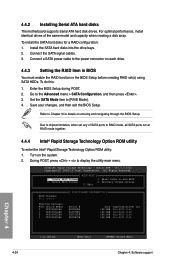
... [ESC]-Exit [ENTER]-Select Menu Chapter 4: Software support To do this: 1. Go to display the utility main menu. Enter the BIOS Setup during POST. 2. Create RAID Volume 3. Connect the SATA signal cables. 3. Connect a SATA power cable to chipset limitation, when set (s) using SATA HDDs. Due... function in the BIOS Setup before creating RAID set any of the same model and capacity when creating a disk array. During POST, press + to the Advanced menu > SATA Configuration, and then press . 3. All Rights Reserved. [ MAIN MENU ] 1. Delete RAID Volume...
... [ESC]-Exit [ENTER]-Select Menu Chapter 4: Software support To do this: 1. Go to display the utility main menu. Enter the BIOS Setup during POST. 2. Create RAID Volume 3. Connect the SATA signal cables. 3. Connect a SATA power cable to chipset limitation, when set (s) using SATA HDDs. Due... function in the BIOS Setup before creating RAID set any of the same model and capacity when creating a disk array. During POST, press + to the Advanced menu > SATA Configuration, and then press . 3. All Rights Reserved. [ MAIN MENU ] 1. Delete RAID Volume...

User Manual
Page 165
... a SATA RAID driver disk. • Windows® XP may not recognize the USB floppy disk drive due to complete the process. Press during POST to create a RAID driver disk. 7. When the Make Disk menu appears, press to enter the BIOS setup utility. 3. Plug the USB floppy ...174; operating system on a hard disk drive that is included in the support DVD: \Drivers\RAID\RSTe\Driver Double-click AsMakeDisk.exe to launch the ASUS MakeDisk Utility. 5. Place the motherboard support DVD into the optical drive. 4. Save changes and exit BIOS. 6. Set the optical drive as the destination...
... a SATA RAID driver disk. • Windows® XP may not recognize the USB floppy disk drive due to complete the process. Press during POST to create a RAID driver disk. 7. When the Make Disk menu appears, press to enter the BIOS setup utility. 3. Plug the USB floppy ...174; operating system on a hard disk drive that is included in the support DVD: \Drivers\RAID\RSTe\Driver Double-click AsMakeDisk.exe to launch the ASUS MakeDisk Utility. 5. Place the motherboard support DVD into the optical drive. 4. Save changes and exit BIOS. 6. Set the optical drive as the destination...


