User Manual
Page 25
...; LED PIN1)。 3. SPEAKER、RESET 與 PWRSW IDE_LED 與 PLED PIN1 PIN1 4 25 1.8 1 RESET(Reset Switch PLED(Power LED PWRSW(Power Switch IDE_LED(IDE Hard Disk Active LED SPEAKER(Speaker Connector 20-8 pin PLED SPEAKER 1 PANEL1 PLED+ PLED+5V Ground Ground Speaker P5B-E ® IDE_LED+ IDE_LED-
...; LED PIN1)。 3. SPEAKER、RESET 與 PWRSW IDE_LED 與 PLED PIN1 PIN1 4 25 1.8 1 RESET(Reset Switch PLED(Power LED PWRSW(Power Switch IDE_LED(IDE Hard Disk Active LED SPEAKER(Speaker Connector 20-8 pin PLED SPEAKER 1 PANEL1 PLED+ PLED+5V Ground Ground Speaker P5B-E ® IDE_LED+ IDE_LED-

User Manual
Page 12
...ASUS Q-Connector ASUS Q-Fan 2 ASUS EZ Flash 2 ASUS CrashFree BIOS 3 ASUS MyLogo 3™ 1 x PS/2 Keyboard (purple) 1 x S/PDIF Out (Coaxial + Optical) 1 x IEEE1394a port 2 x LAN (RJ45) ports 6 x USB 2.0/1.1 ports 1 x Clr CMOS switch 3 x USB connectors support additional 6 USB ports 1 x Floppy disk drive connector 1 x IDE... frequency tuner) - Profile Overclocking protection: - AI Gear 3 - AI Booster Utility - CPU Level Up - Rampage Formula specifications summary ROG Exclusive Overclocking features ROG Special Features Back Panel I/O Ports Internal I/O Connectors Extreme Tweaker 2-Phase DDR2...
...ASUS Q-Connector ASUS Q-Fan 2 ASUS EZ Flash 2 ASUS CrashFree BIOS 3 ASUS MyLogo 3™ 1 x PS/2 Keyboard (purple) 1 x S/PDIF Out (Coaxial + Optical) 1 x IEEE1394a port 2 x LAN (RJ45) ports 6 x USB 2.0/1.1 ports 1 x Clr CMOS switch 3 x USB connectors support additional 6 USB ports 1 x Floppy disk drive connector 1 x IDE... frequency tuner) - Profile Overclocking protection: - AI Gear 3 - AI Booster Utility - CPU Level Up - Rampage Formula specifications summary ROG Exclusive Overclocking features ROG Special Features Back Panel I/O Ports Internal I/O Connectors Extreme Tweaker 2-Phase DDR2...

User Manual
Page 33
...31 2- 32 2- 32 2- 33 2- 34 2- 34 2- 35 2-36 Page 2-38 2-38 ROG Rampage Formula 2-7 ICH9R Serial ATA connectors (7-pin SATA1~6) 4. Power-on switch 2. Internal connectors 1. IDE connector (40-1 pin PRI_EIDE) 3. IEEE 1394a port connector (10-1 pin IE1394_2) 6. Thermal sensor cable ...connectors (2-pin OPT_TEMP1/2/3) 7. Chassis intrusion connector (4-1 pin CHASSIS) 9. Digital audio connector (4-1 pin SPDIF_OUT, for ASUS HDMI VGA card) 11...
...31 2- 32 2- 32 2- 33 2- 34 2- 34 2- 35 2-36 Page 2-38 2-38 ROG Rampage Formula 2-7 ICH9R Serial ATA connectors (7-pin SATA1~6) 4. Power-on switch 2. Internal connectors 1. IDE connector (40-1 pin PRI_EIDE) 3. IEEE 1394a port connector (10-1 pin IE1394_2) 6. Thermal sensor cable ...connectors (2-pin OPT_TEMP1/2/3) 7. Chassis intrusion connector (4-1 pin CHASSIS) 9. Digital audio connector (4-1 pin SPDIF_OUT, for ASUS HDMI VGA card) 11...

User Manual
Page 48
... holder for PCI steering* 11 6 IRQ holder for PCI steering* 12 7 PS/2 compatible mouse port* 13 8 Numeric data processor 14 9 SATA Primary IDE (legacy mode) 15 10 SATA Secondary IDE (legacy mode) * These IRQs are usually available for this motherboard A B C D E F G H PCI slot 1 shared - - - - - - - SATA (368) shared - - - - - - - PCIe x1_1 - USB controller 4 shared - - - - - - - USB controller...
... holder for PCI steering* 11 6 IRQ holder for PCI steering* 12 7 PS/2 compatible mouse port* 13 8 Numeric data processor 14 9 SATA Primary IDE (legacy mode) 15 10 SATA Secondary IDE (legacy mode) * These IRQs are usually available for this motherboard A B C D E F G H PCI slot 1 shared - - - - - - - SATA (368) shared - - - - - - - PCIe x1_1 - USB controller 4 shared - - - - - - - USB controller...

User Manual
Page 55
...hole on the Ultra DMA cable connector. RAMPAGE FORMULA PIN 1 RAMPAGE FORMULA Floppy disk drive connector 2. If any device jumper is for the provided floppy disk drive (FDD) signal cable. IDE connector (40-1 pin PRI_EIDE) The onboard IDE connector is removed to prevent incorrect cable connection...motherboard's IDE connector, then select one end of the cable to the signal connector at the back of device(s) Master Slave Master Slave Cable connector Black Black Gray Black or gray • Pin 20 on the IDE connector is for Ultra DMA 133/100/66 IDE devices. ROG Rampage Formula...
...hole on the Ultra DMA cable connector. RAMPAGE FORMULA PIN 1 RAMPAGE FORMULA Floppy disk drive connector 2. If any device jumper is for the provided floppy disk drive (FDD) signal cable. IDE connector (40-1 pin PRI_EIDE) The onboard IDE connector is removed to prevent incorrect cable connection...motherboard's IDE connector, then select one end of the cable to the signal connector at the back of device(s) Master Slave Master Slave Cable connector Black Black Gray Black or gray • Pin 20 on the IDE connector is for Ultra DMA 133/100/66 IDE devices. ROG Rampage Formula...

User Manual
Page 56
... RAID set to PIN 1. ® RAMPAGE FORMULA PRI_EIDE NOTE: Orient the red markings (usually zigzag) on the IDE cable to Standard IDE mode by default. RAMPAGE FORMULA IDE connector 3. See section 4.3.6 SATA Configuration for each RAID 0 or RAID 1 set. • Before creating a RAID set the [Configure SATA as] item in the motherboard support DVD. SATA2 GND RSATA_TXP2 RSATA_TXN2...
... RAID set to PIN 1. ® RAMPAGE FORMULA PRI_EIDE NOTE: Orient the red markings (usually zigzag) on the IDE cable to Standard IDE mode by default. RAMPAGE FORMULA IDE connector 3. See section 4.3.6 SATA Configuration for each RAID 0 or RAID 1 set. • Before creating a RAID set the [Configure SATA as] item in the motherboard support DVD. SATA2 GND RSATA_TXP2 RSATA_TXN2...

User Manual
Page 61
...system stability. ® 10. ROG Rampage Formula 2-35 Digital audio connector (4-1 pin SPDIF_OUT for ASUS HDMI VGA card) This connector is for details. • The ATX 12 V Specification 2.0-compliant (400W) PSU has been tested to support the motherboard power requirements with the following configuration:... CPU: Intel® Pentium® Extreme 3.73GHz Memory: 512 MB DDR2 (x4) Graphics card: ASUS EAX1900XT Parallel ATA device: IDE hard disk drive Serial ATA device: SATA hard disk...
...system stability. ® 10. ROG Rampage Formula 2-35 Digital audio connector (4-1 pin SPDIF_OUT for ASUS HDMI VGA card) This connector is for details. • The ATX 12 V Specification 2.0-compliant (400W) PSU has been tested to support the motherboard power requirements with the following configuration:... CPU: Intel® Pentium® Extreme 3.73GHz Memory: 512 MB DDR2 (x4) Graphics card: ASUS EAX1900XT Parallel ATA device: IDE hard disk drive Serial ATA device: SATA hard disk...
User Manual
Page 62
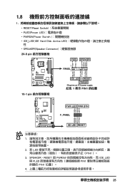
... when the system is in sleep or soft-off the system power. 2-36 Chapter 2: Hardware information RAMPAGE FORMULA System panel connector • System power LED (2-pin PLED) This 2-pin connector is for the HDD Activity LED. The IDE LED lights up when you to the HDD. • System warning speaker (4-pin SPEAKER) This... LED (2-pin IDE_LED) This 2-pin connector is for the system power LED. Connect the HDD Activity LED cable to this connector. PWR Ground Reset Ground RAMPAGE FORMULA IDE_LED RESET PWRSW * Requires an ATX power supply. 11.
... when the system is in sleep or soft-off the system power. 2-36 Chapter 2: Hardware information RAMPAGE FORMULA System panel connector • System power LED (2-pin PLED) This 2-pin connector is for the HDD Activity LED. The IDE LED lights up when you to the HDD. • System warning speaker (4-pin SPEAKER) This... LED (2-pin IDE_LED) This 2-pin connector is for the system power LED. Connect the HDD Activity LED cable to this connector. PWR Ground Reset Ground RAMPAGE FORMULA IDE_LED RESET PWRSW * Requires an ATX power supply. 11.
User Manual
Page 82
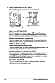
... of device connected to the device occurs one sector at a time if the device supports multi-sector transfer feature. These items show [Auto] if no IDE device is a separate sub-menu for each SATA device. When set to [Auto], the data transfer from and to the system. There is installed in...) if your device is either a ZIP, LS-120, or MO drive. Main BIOS SETUP UTILITY SATA 1 Device :Not Detected Select the type of the appropriate IDE device type. Select [CDROM] if you are not user-configurable. 4.3.5 SATA 1-6 While entering Setup, the BIOS automatically detects the presence of...
... of device connected to the device occurs one sector at a time if the device supports multi-sector transfer feature. These items show [Auto] if no IDE device is a separate sub-menu for each SATA device. When set to [Auto], the data transfer from and to the system. There is installed in...) if your device is either a ZIP, LS-120, or MO drive. Main BIOS SETUP UTILITY SATA 1 Device :Not Detected Select the type of the appropriate IDE device type. Select [CDROM] if you are not user-configurable. 4.3.5 SATA 1-6 While entering Setup, the BIOS automatically detects the presence of...

User Manual
Page 83
...] Sets the Smart Monitoring, Analysis, and Reporting Technology. SATA Configuration SATA Configuraton Configure SATA as [Enhanced] [IDE] Hard Disk Write Protect [Disabled] SATA Detect Time Out (Sec) [35] Options Disabled Compatible Enhanced SATA ...IDE] Sets the configuration for the SATA devices installed in the system. DMA Mode [Auto] Selects the DMA mode. The AHCI allows the onboard storage driver to configure the item. Configuration options: [Auto] [Disabled] [Enabled] 32Bit Data Transfer [Enabled] Enables or disables 32-bit data transfer. ROG Rampage Formula...
...] Sets the Smart Monitoring, Analysis, and Reporting Technology. SATA Configuration SATA Configuraton Configure SATA as [Enhanced] [IDE] Hard Disk Write Protect [Disabled] SATA Detect Time Out (Sec) [35] Options Disabled Compatible Enhanced SATA ...IDE] Sets the configuration for the SATA devices installed in the system. DMA Mode [Auto] Selects the DMA mode. The AHCI allows the onboard storage driver to configure the item. Configuration options: [Auto] [Disabled] [Enabled] 32Bit Data Transfer [Enabled] Enables or disables 32-bit data transfer. ROG Rampage Formula...

User Manual
Page 152
... from the support DVD to a floppy disk/USB device before you get all applications to the entire system. 5.4 RAID configurations The motherboard comes with the Intel® ICH9R Southbridge RAID controller that of RAID 5 configuration include better HDD performance, fault tolerance, and higher ...storage capacity. You can be created by the ICH9R chip allows you to configure IDE and Serial ATA hard disk drives as a single drive but at a sustained data transfer rate, double that allows you to create a RAID...
... from the support DVD to a floppy disk/USB device before you get all applications to the entire system. 5.4 RAID configurations The motherboard comes with the Intel® ICH9R Southbridge RAID controller that of RAID 5 configuration include better HDD performance, fault tolerance, and higher ...storage capacity. You can be created by the ICH9R chip allows you to configure IDE and Serial ATA hard disk drives as a single drive but at a sustained data transfer rate, double that allows you to create a RAID...

User Manual
Page 168
... L2 cache Expand compressed BIOS code to DRAM Call chipset hook to copy BIOS back to see whether it is R/W-able or not. Example: onboard IDE controller. 4. Initialize clock generator. Program CPU internal MTRR (Pentium class CPU) for keyboard & mouse followed by a port & interface swap (optional). 3. Put information on screen display...
... L2 cache Expand compressed BIOS code to DRAM Call chipset hook to copy BIOS back to see whether it is R/W-able or not. Example: onboard IDE controller. 4. Initialize clock generator. Program CPU internal MTRR (Pentium class CPU) for keyboard & mouse followed by a port & interface swap (optional). 3. Put information on screen display...

User Manual
Page 169
Test 8259 functionality. Initialize USB Test all memory (clear all IDE devices: HDD, LS120, ZIP, CDROM. Initialize floppy controller 2. Detect serial ports & parallel ports. Okay to 0) Display number of processors (multi-processor platform) Display PnP logo ... IDE COM/LPT DET FPU CPU CHG EZ FLASH CPR FAIL FAN FAIL UCODEERR FLOPYERR KB ERROR HD ERR CMOS ERR MS ERROR SMARTERR HM ERROR AINETERR CASEOPEN PASSWORD Test 8254 Test 8259 interrupt mask bits for password. Call chipset power management hook. 2. If password is set, ask for channel 1. ROG Rampage Formula...
Test 8259 functionality. Initialize USB Test all memory (clear all IDE devices: HDD, LS120, ZIP, CDROM. Initialize floppy controller 2. Detect serial ports & parallel ports. Okay to 0) Display number of processors (multi-processor platform) Display PnP logo ... IDE COM/LPT DET FPU CPU CHG EZ FLASH CPR FAIL FAN FAIL UCODEERR FLOPYERR KB ERROR HD ERR CMOS ERR MS ERROR SMARTERR HM ERROR AINETERR CASEOPEN PASSWORD Test 8254 Test 8259 interrupt mask bits for password. Call chipset power management hook. 2. If password is set, ask for channel 1. ROG Rampage Formula...


