
User Guide
Page 5
...Chapter 5: RAID configuration 5.1 Setting up RAID 5-1 5.1.1 RAID definitions 5-1 5.1.2 Installing hard disk drives 5-2 5.1.3 Setting the RAID item in BIOS 5-2 5.1.4 RAID configuration utilities 5-3 5.2 LSI Logic Embedded SATA RAID Setup Utility 5-4 5.2.1 Creating a RAID set 5-5 5.2.2 Adding or viewing... set 5-25 5.2.8 Enabling the WriteCache 5-26 5.3 Global Array Manager 5-26 5.4 Adaptec SCSISelect(TM) Utility 5-27 (PVL-D/SCSI model only) 5.4.1 Configuring the SCSI controller 5-28 5.4.2 Enabling the HostRAID controller 5-28 5.4.3 Creating a RAID 0 set (Stripe 5-29 5.4.4 Creating a ...
...Chapter 5: RAID configuration 5.1 Setting up RAID 5-1 5.1.1 RAID definitions 5-1 5.1.2 Installing hard disk drives 5-2 5.1.3 Setting the RAID item in BIOS 5-2 5.1.4 RAID configuration utilities 5-3 5.2 LSI Logic Embedded SATA RAID Setup Utility 5-4 5.2.1 Creating a RAID set 5-5 5.2.2 Adding or viewing... set 5-25 5.2.8 Enabling the WriteCache 5-26 5.3 Global Array Manager 5-26 5.4 Adaptec SCSISelect(TM) Utility 5-27 (PVL-D/SCSI model only) 5.4.1 Configuring the SCSI controller 5-28 5.4.2 Enabling the HostRAID controller 5-28 5.4.3 Creating a RAID 0 set (Stripe 5-29 5.4.4 Creating a ...

User Guide
Page 12
... Power Requirement Form Factor Support CD contents ASUS Smart Fan Control ASUS CrashFree BIOS 2 ASUS MyLogo2 AMI BIOS, 8 Mb FWH, Green, PnP, DMI2.0a, ACPI 2.0a SMBIOS 2.3, WfM2.0 1 x PS/2 keyboard port (purple) 1 x PS/2 mouse port (green) 2 x USB 2.0 ports 1 x Serial port 1 x VGA port 2 x LAN (RJ-45) ports 1 x Parallel port (PVL-D/SCSI model only) 1 x Floppy disk drive connector 2 x IDE...
... Power Requirement Form Factor Support CD contents ASUS Smart Fan Control ASUS CrashFree BIOS 2 ASUS MyLogo2 AMI BIOS, 8 Mb FWH, Green, PnP, DMI2.0a, ACPI 2.0a SMBIOS 2.3, WfM2.0 1 x PS/2 keyboard port (purple) 1 x PS/2 mouse port (green) 2 x USB 2.0 ports 1 x Serial port 1 x VGA port 2 x LAN (RJ-45) ports 1 x Parallel port (PVL-D/SCSI model only) 1 x Floppy disk drive connector 2 x IDE...

User Guide
Page 28
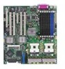
... pin selection (3-pin FM_CPU1, FM_CPU2) 3. USB device wake-up (3-pin USBPW12, USBPW34) 4. Gigabit LAN controller setting (3-pin LAN1_EN1) 7. Force BIOS recovery setting (3-pin RECOVERY1) Rear panel connectors 1. USB 2.0 ports 1 and 2 4. Keyboard power (3-pin KBPWR1) 5. PS/2 keyboard port (... setting (3-pin LAN2_EN1) 8. Zero-Channel RAID socket 5. VGA controller setting (3-pin VGA_EN1) 6. SCSI controller setting (3-pin SCSI_EN1) 9. Gigabit LAN (RJ-45) ports 7. Parallel port (for PVL-D/SCSI model only) 3. Serial (COM1) port 5. VGA port 6. PCI/PCI-X slots 4. DDR2 DIMM...
... pin selection (3-pin FM_CPU1, FM_CPU2) 3. USB device wake-up (3-pin USBPW12, USBPW34) 4. Gigabit LAN controller setting (3-pin LAN1_EN1) 7. Force BIOS recovery setting (3-pin RECOVERY1) Rear panel connectors 1. USB 2.0 ports 1 and 2 4. Keyboard power (3-pin KBPWR1) 5. PS/2 keyboard port (... setting (3-pin LAN2_EN1) 8. Zero-Channel RAID socket 5. VGA controller setting (3-pin VGA_EN1) 6. SCSI controller setting (3-pin SCSI_EN1) 9. Gigabit LAN (RJ-45) ports 7. Parallel port (for PVL-D/SCSI model only) 3. Serial (COM1) port 5. VGA port 6. PCI/PCI-X slots 4. DDR2 DIMM...
User Guide
Page 41
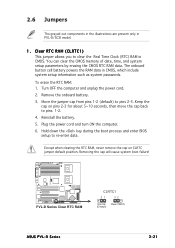
...cord and turn ON the computer. 6. Hold down the key during the boot process and enter BIOS setup to pins 2-3. PVL-D Series ® PVL-D Series Clear RTC RAM CLRTC1 21 32 Normal Clear CMOS (Default) ASUS PVL-D Series 2-21 Reinstall the battery. 5. Except when clearing the RTC RAM, never remove the ... failure! Keep the cap on CLRTC jumper default position. 2.6 Jumpers The grayed out components in the illustrations are present only in PVL-D/SCSI model. 1. Move the jumper cap from pins 1-2 (default) to re-enter data. Turn OFF the computer and unplug the power cord. 2.
...cord and turn ON the computer. 6. Hold down the key during the boot process and enter BIOS setup to pins 2-3. PVL-D Series ® PVL-D Series Clear RTC RAM CLRTC1 21 32 Normal Clear CMOS (Default) ASUS PVL-D Series 2-21 Reinstall the battery. 5. Except when clearing the RTC RAM, never remove the ... failure! Keep the cap on CLRTC jumper default position. 2.6 Jumpers The grayed out components in the illustrations are present only in PVL-D/SCSI model. 1. Move the jumper cap from pins 1-2 (default) to re-enter data. Turn OFF the computer and unplug the power cord. 2.
User Guide
Page 45
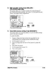
... pins 1-2 to pins 1-2. 6. Insert the floppy disk then turn on the system. PVL-D Series ® RECOVERY1 12 23 Normal BIOS Recovery (Default) PVL-D Series BIOS recovery setting ASUS PVL-D Series 2-25 Turn on the system to pins 2-3. 3. 8 . Prepare a floppy disk that contains the latest BIOS for the motherboard (xxxx-xxx.ROM) and the AFUDOS.EXE utility. 2. Set...
... pins 1-2 to pins 1-2. 6. Insert the floppy disk then turn on the system. PVL-D Series ® RECOVERY1 12 23 Normal BIOS Recovery (Default) PVL-D Series BIOS recovery setting ASUS PVL-D Series 2-25 Turn on the system to pins 2-3. 3. 8 . Prepare a floppy disk that contains the latest BIOS for the motherboard (xxxx-xxx.ROM) and the AFUDOS.EXE utility. 2. Set...

User Guide
Page 59
...turned on the power, the system may light up for assistance. While the tests are off. 3. AMI BIOS beep codes Beep Description One beep Two continuous beeps followed by two short beeps Two continuous beeps followed by four... the power connector at the back of the system chassis. 4. Be sure that is equipped with a surge protector. 5. External SCSI devices (starting with "green" standards or if it has a "power standby" feature, the monitor LED may have failed a ... up or switch between orange and green after the system LED turns on. ASUS PVL-D Series 3-1 System power 6.
...turned on the power, the system may light up for assistance. While the tests are off. 3. AMI BIOS beep codes Beep Description One beep Two continuous beeps followed by two short beeps Two continuous beeps followed by four... the power connector at the back of the system chassis. 4. Be sure that is equipped with a surge protector. 5. External SCSI devices (starting with "green" standards or if it has a "power standby" feature, the monitor LED may have failed a ... up or switch between orange and green after the system LED turns on. ASUS PVL-D Series 3-1 System power 6.
User Guide
Page 65
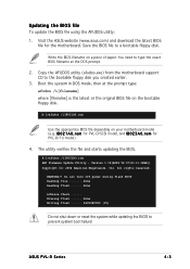
... CD to prevent system boot failure! Version 1.19(ASUS V2.07(03.11.24BB)) Copyright (C) 2002 American Megatrends, Inc. done Writing flash ...... 0x0008CC00 (9%) Do not shut down or reset the system while updating the BIOS to the bootable floppy disk you created earlier. 3. r o m for PVL-D/SCSI model, and I 8 0 2 1 A 0 . The utility verifies the file and...
... CD to prevent system boot failure! Version 1.19(ASUS V2.07(03.11.24BB)) Copyright (C) 2002 American Megatrends, Inc. done Writing flash ...... 0x0008CC00 (9%) Do not shut down or reset the system while updating the BIOS to the bootable floppy disk you created earlier. 3. r o m for PVL-D/SCSI model, and I 8 0 2 1 A 0 . The utility verifies the file and...
User Guide
Page 67
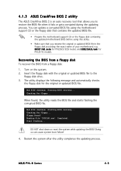
... or reset the system while updating the BIOS! Turn on the system. 2. Starting BIOS recovery... Floppy found , the utility reads the BIOS file and starts flashing the corrupted BIOS file. r o m for the original or updated BIOS file. Reading file "I8021A0.rom". Checking for floppy... Completed. ASUS PVL-D Series 4-5 r o m for PVLDSCI/SCSI model, and I 8 0 2 1 A 0 . Doing so can update a corrupted...
... or reset the system while updating the BIOS! Turn on the system. 2. Starting BIOS recovery... Floppy found , the utility reads the BIOS file and starts flashing the corrupted BIOS file. r o m for the original or updated BIOS file. Reading file "I8021A0.rom". Checking for floppy... Completed. ASUS PVL-D Series 4-5 r o m for PVLDSCI/SCSI model, and I 8 0 2 1 A 0 . Doing so can update a corrupted...

User Guide
Page 78
...ESC Exit v02.58 (C)Copyright 1985-2004, American Megatrends, Inc. Model Name Displays the auto-detected ASUS motherboard model (either PVL-D/SCSI, or PVL-D/1U). ASUS BIOS Displays the auto-detected BIOS version in this menu. Configuration options: [Auto] [0] [1] [2] [3] [4] DMA Mode [Auto] ...] SMART Monitoring [Auto] Sets the Smart Monitoring, Analysis, and Reporting Technology. Main System Information BIOS SETUP UTILITY Model Name ASUS PVL-D/SCSI Model ID 8021A0 ASUS-BIOS Version Date 1001 09/20/2005 Processor System Memory Select Screen Select Item +- Model ID Displays ...
...ESC Exit v02.58 (C)Copyright 1985-2004, American Megatrends, Inc. Model Name Displays the auto-detected ASUS motherboard model (either PVL-D/SCSI, or PVL-D/1U). ASUS BIOS Displays the auto-detected BIOS version in this menu. Configuration options: [Auto] [0] [1] [2] [3] [4] DMA Mode [Auto] ...] SMART Monitoring [Auto] Sets the Smart Monitoring, Analysis, and Reporting Technology. Main System Information BIOS SETUP UTILITY Model Name ASUS PVL-D/SCSI Model ID 8021A0 ASUS-BIOS Version Date 1001 09/20/2005 Processor System Memory Select Screen Select Item +- Model ID Displays ...

User Guide
Page 82
... sub-menu. Select an item then press to enable or disable the option ROM in the onboard SCSI controller. Select Screen Select Item +- Onboard LAN Boot ROM [Enabled] Allows you to change the ... to enable or disable the option ROM in the onboard LAN controller. Advanced Advanced Chipset Settings BIOS SETUP UTILITY WARNING: Setting wrong values in below sections may cause system to malfunction. Change Option... Megatrends, Inc. Northbridge Configuration Onboard LAN Boot ROM Onboard SCSI Boot ROM [Enabled] [Enabled] Options for NB. Configuration options: [Disabled] [Enabled] The above item...
... sub-menu. Select an item then press to enable or disable the option ROM in the onboard SCSI controller. Select Screen Select Item +- Onboard LAN Boot ROM [Enabled] Allows you to change the ... to enable or disable the option ROM in the onboard LAN controller. Advanced Advanced Chipset Settings BIOS SETUP UTILITY WARNING: Setting wrong values in below sections may cause system to malfunction. Change Option... Megatrends, Inc. Northbridge Configuration Onboard LAN Boot ROM Onboard SCSI Boot ROM [Enabled] [Enabled] Options for NB. Configuration options: [Disabled] [Enabled] The above item...

User Guide
Page 108
...motherboard supports Serial ATA (both models) and SCSI hard disk drives (PVL-D/SCSI model only) for RAID set the C o n f i g u r e S - Install the SATA hard disks into the drive bays following the instructions in the BIOS Setup before you can create a RAID set ...p p o r t O n item to [Enhanced Mode], then press . 4. Save your changes, then exit the BIOS Setup. Refer to the SCSI connector on the motherboard. 5.1.3 Setting the RAID item in BIOS You must set the RAID item in the system user guide. 2. Install the SCSI hard disks into the drive bays following the instructions in the system...
...motherboard supports Serial ATA (both models) and SCSI hard disk drives (PVL-D/SCSI model only) for RAID set the C o n f i g u r e S - Install the SATA hard disks into the drive bays following the instructions in the BIOS Setup before you can create a RAID set ...p p o r t O n item to [Enhanced Mode], then press . 4. Save your changes, then exit the BIOS Setup. Refer to the SCSI connector on the motherboard. 5.1.3 Setting the RAID item in BIOS You must set the RAID item in the system user guide. 2. Install the SCSI hard disks into the drive bays following the instructions in the system...

User Guide
Page 133
... the system after installing all the SCSI hard disk drives. 2. ASUS PVL-D Series 5-27 5.4 Adaptec SCSISelect(TM) Utility! (PVL-D/SCSI model only) The Adaptec SCSISelect(TM) Utility allows you to create RAID 0, 1, and 0+1 set (s). The utility auto-detects the available SCSI channels. During POST, the Adaptec SCSI BIOS automatically detects the installed SCSI hard disk drives and displays any...
... the system after installing all the SCSI hard disk drives. 2. ASUS PVL-D Series 5-27 5.4 Adaptec SCSISelect(TM) Utility! (PVL-D/SCSI model only) The Adaptec SCSISelect(TM) Utility allows you to create RAID 0, 1, and 0+1 set (s). The utility auto-detects the available SCSI channels. During POST, the Adaptec SCSI BIOS automatically detects the installed SCSI hard disk drives and displays any...

User Guide
Page 175
A.1 PVL-D/SCSI block diagram PCIE2 Intel with 800 MHz system bus System Bus 64-bit, 800 MHz Intel with 800 MHz system ... Express PCI bridge Intel PXH X8 PCI Express PCI-X 1.0 bus (64Bit/133(100)MHz) PCI-X 1.0 bus (64Bit/133(100)MHz) Adaptec SCSI-Controller AIC7902 ZCR SO-DIMM Type socket X1 PCI Express X1 PCI Express Gigabit LAN1 BCM5721 Gigabit LAN2 BCM5721 LAN Port 1 LAN Port 2 Hub... 8 Mbyte VGA-Conn. H/W monitor W83792D Fan Power Supply EEPROM System information MINI_PCI Super I/O W83627THF-A Keyboard 1st Serial Port Floppy Mouse BIOS Flash 8 Mbit ASUS PVL-D Series A-1
A.1 PVL-D/SCSI block diagram PCIE2 Intel with 800 MHz system bus System Bus 64-bit, 800 MHz Intel with 800 MHz system ... Express PCI bridge Intel PXH X8 PCI Express PCI-X 1.0 bus (64Bit/133(100)MHz) PCI-X 1.0 bus (64Bit/133(100)MHz) Adaptec SCSI-Controller AIC7902 ZCR SO-DIMM Type socket X1 PCI Express X1 PCI Express Gigabit LAN1 BCM5721 Gigabit LAN2 BCM5721 LAN Port 1 LAN Port 2 Hub... 8 Mbyte VGA-Conn. H/W monitor W83792D Fan Power Supply EEPROM System information MINI_PCI Super I/O W83627THF-A Keyboard 1st Serial Port Floppy Mouse BIOS Flash 8 Mbit ASUS PVL-D Series A-1
