PU-DLS User Manual
Page 3
... in this guide ix Where to find more information ix ASUS contact information x PU-DLS specifications summary xi Chapter 1: Product introduction 1.1 Welcome 1-1 1.2 Package contents 1-1 1.3 Special features 1-2 1.3.1 Product highlights 1-2 1.3.2 Value-added solutions 1-4 1.4 Motherboard overview 1-6 1.4.1 Major components 1-6 1.4.2 Core specifications 1-8 Chapter 2: Hardware information 2.1 Motherboard installation 2-1 2.1.1 Placement direction 2-1 2.1.2 Screw holes 2-1 2.2 Motherboard layout 2-2 2.3 Before you proceed 2-3 2.4 Central Processing Unit (CPU 2-4 2.4.1 Overview...
... in this guide ix Where to find more information ix ASUS contact information x PU-DLS specifications summary xi Chapter 1: Product introduction 1.1 Welcome 1-1 1.2 Package contents 1-1 1.3 Special features 1-2 1.3.1 Product highlights 1-2 1.3.2 Value-added solutions 1-4 1.4 Motherboard overview 1-6 1.4.1 Major components 1-6 1.4.2 Core specifications 1-8 Chapter 2: Hardware information 2.1 Motherboard installation 2-1 2.1.1 Placement direction 2-1 2.1.2 Screw holes 2-1 2.2 Motherboard layout 2-2 2.3 Before you proceed 2-3 2.4 Central Processing Unit (CPU 2-4 2.4.1 Overview...
PU-DLS User Manual
Page 11
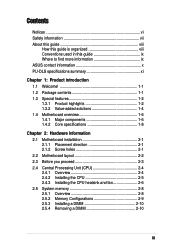
PU-DLS specifications summary CPU Chipsets Front Side Bus (FSB) Memory Onboard LAN Onboard SCSI Expansion slots Rear panel I/O Internal connectors ...MHz 6 x 184-pin DDR DIMM sockets Supports PC2100/PC1600 registered ECC DDR DIMMs Supports up to 12GB system memory using 2GB DIMMs Intel® 82540EM 32-bit PCI Gigabit Ethernet controller Intel® 82544GC 64-bit PCI-X Gigabit... 4Mb Firmware Hub (FWH), Award BIOS with ACPI, DMI, Green, PnP features, and Enhanced Server BIOS features Extended ATX form factor: 12 in x 13 in (30.5 cm x 33 cm) Device drivers Utilities Contact information * Specifications are...
PU-DLS specifications summary CPU Chipsets Front Side Bus (FSB) Memory Onboard LAN Onboard SCSI Expansion slots Rear panel I/O Internal connectors ...MHz 6 x 184-pin DDR DIMM sockets Supports PC2100/PC1600 registered ECC DDR DIMMs Supports up to 12GB system memory using 2GB DIMMs Intel® 82540EM 32-bit PCI Gigabit Ethernet controller Intel® 82544GC 64-bit PCI-X Gigabit... 4Mb Firmware Hub (FWH), Award BIOS with ACPI, DMI, Green, PnP features, and Enhanced Server BIOS features Extended ATX form factor: 12 in x 13 in (30.5 cm x 33 cm) Device drivers Utilities Contact information * Specifications are...
PU-DLS User Manual
Page 16
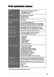
... network applications. 1.3 Special features 1.3.1 Product highlights Latest processor technology The PU-DLS motherboard supports the Intel® Xeon processor via dual 604-pin surface mount ZIF sockets. DDR memory support Employing the Double Data Rate (DDR) memory technology, the PU-DLS motherboard supports up to 12GB of system memory using PC2100/1600 registered ECC DDR DIMMs. The ultra-fast...
... network applications. 1.3 Special features 1.3.1 Product highlights Latest processor technology The PU-DLS motherboard supports the Intel® Xeon processor via dual 604-pin surface mount ZIF sockets. DDR memory support Employing the Double Data Rate (DDR) memory technology, the PU-DLS motherboard supports up to 12GB of system memory using PC2100/1600 registered ECC DDR DIMMs. The ultra-fast...

PU-DLS User Manual
Page 18
...monitored for operating systems that provides more than 4 seconds puts the system to sleep mode or to the memory and processor. The system fan rotations per minute (RPM) is Year 2000 certified. 1-4 Chapter 1: Product ...feature, the chassis intrusion circuitry logs "chassis-open" events into the system BIOS. Wake-Up support The motherboard includes Wake-On-LAN, Wake-On-Ring, and BIOS Wake-Up features. ACPI ready The Advanced Configuration ...fan, and voltage monitoring The CPU temperature is monitored by the ASUS ASIC to -use interface that support OS Direct Power Management (OSPM).
...monitored for operating systems that provides more than 4 seconds puts the system to sleep mode or to the memory and processor. The system fan rotations per minute (RPM) is Year 2000 certified. 1-4 Chapter 1: Product ...feature, the chassis intrusion circuitry logs "chassis-open" events into the system BIOS. Wake-Up support The motherboard includes Wake-On-LAN, Wake-On-Ring, and BIOS Wake-Up features. ACPI ready The Advanced Configuration ...fan, and voltage monitoring The CPU temperature is monitored by the ASUS ASIC to -use interface that support OS Direct Power Management (OSPM).
PU-DLS User Manual
Page 22
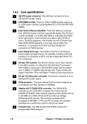
... supply. 2 DDR DIMM sockets. 1.4.2 Core specifications 1 SSI/ATX power connector. This 24/20-pin connector is a PC 2000-2001-compliant PCI-X dual-channel Ultra320 SCSI ASIC. The E7501 Memory Controller Hub (MCH) processor interface supports the System Bus Protocol at peak bandwidth of 3.2 GB/s (400 MHz) or 4....pin surface mount, Zero Insertion Force (ZIF) sockets are onboard for an SSI-type/ATX power supply. 7 SCSI connector. This 8/4-pin connector is PCI/PCI-X 64-bit Hub 2 that allows up to 12GB system memory using registered ECC PC2100/1600 DDR DIMMs. 3 Intel® E7501 (Plumas 533) ...
... supply. 2 DDR DIMM sockets. 1.4.2 Core specifications 1 SSI/ATX power connector. This 24/20-pin connector is a PC 2000-2001-compliant PCI-X dual-channel Ultra320 SCSI ASIC. The E7501 Memory Controller Hub (MCH) processor interface supports the System Bus Protocol at peak bandwidth of 3.2 GB/s (400 MHz) or 4....pin surface mount, Zero Insertion Force (ZIF) sockets are onboard for an SSI-type/ATX power supply. 7 SCSI connector. This 8/4-pin connector is PCI/PCI-X 64-bit Hub 2 that allows up to 12GB system memory using registered ECC PC2100/1600 DDR DIMMs. 3 Intel® E7501 (Plumas 533) ...
PU-DLS User Manual
Page 26
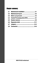
Chapter summary 2.1 Motherboard installation 2-1 2.2 Motherboard layout 2-2 2.3 Before you proceed 2-3 2.4 Central Processing Unit (CPU 2-4 2.5 System memory 2-8 2.6 Expansion slots 2-11 2.7 Jumpers 2-14 2.8 Connectors 2-18 ASUS PU-DLS motherboard
Chapter summary 2.1 Motherboard installation 2-1 2.2 Motherboard layout 2-2 2.3 Before you proceed 2-3 2.4 Central Processing Unit (CPU 2-4 2.5 System memory 2-8 2.6 Expansion slots 2-11 2.7 Jumpers 2-14 2.8 Connectors 2-18 ASUS PU-DLS motherboard

PU-DLS User Manual
Page 34
...Data Rate (DDR) Dual Inline Memory Module (DIMM) sockets. DO NOT force a DIMM into a socket to 12GB system memory using 184-pin registered PC2100/1600 DIMMs with Serial Presence Detect (SPD) and Error Check and Correction (ECC). ® PU-DLS PU-DLS 184-Pin DDR DIMM Sockets 104... twice the throughput of the SDR DIMM. For example, a 200MHz DDR DIMM will support a 100MHz memory bus, and a 266MHz DDR DIMM will support a 133MHz memory bus. 2.5 System memory 2.5.1 Overview The motherboard comes with SDR, and should be installed only in a socket specially designed for DDR DIMMs. 2-8 ...
...Data Rate (DDR) Dual Inline Memory Module (DIMM) sockets. DO NOT force a DIMM into a socket to 12GB system memory using 184-pin registered PC2100/1600 DIMMs with Serial Presence Detect (SPD) and Error Check and Correction (ECC). ® PU-DLS PU-DLS 184-Pin DDR DIMM Sockets 104... twice the throughput of the SDR DIMM. For example, a 200MHz DDR DIMM will support a 100MHz memory bus, and a 266MHz DDR DIMM will support a 133MHz memory bus. 2.5 System memory 2.5.1 Overview The motherboard comes with SDR, and should be installed only in a socket specially designed for DDR DIMMs. 2-8 ...
PU-DLS User Manual
Page 35
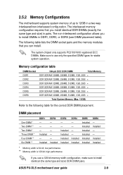
... is 64-bit; The non-interleaved configuration allows you can install. Installed Installed Installed Installed DDR4 - - - - ASUS PU-DLS motherboard user guide 2-9 2.5.2 Memory Configurations The motherboard supports system memory of up to 12GB in pairs. Installed DDR2 - - - - - high performance If you install identical DDR DIMMs (exactly the same type and size) in a two-way ...
... is 64-bit; The non-interleaved configuration allows you can install. Installed Installed Installed Installed DDR4 - - - - ASUS PU-DLS motherboard user guide 2-9 2.5.2 Memory Configurations The motherboard supports system memory of up to 12GB in pairs. Installed DDR2 - - - - - high performance If you install identical DDR DIMMs (exactly the same type and size) in a two-way ...
PU-DLS User Manual
Page 43
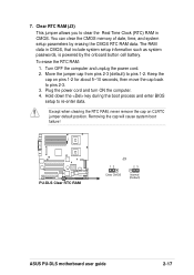
... you to pins 1-2. Keep the cap on CLRTC jumper default position. Removing the cap will cause system boot failure! ® PU-DLS PU-DLS Clear RTC RAM J3 12 23 Clear CMOS Normal (Default) ASUS PU-DLS motherboard user guide 2-17 Hold down the key during the boot process and enter BIOS setup to pins 2-3. 3. The RAM data... 5~10 seconds, then move the cap back to re-enter data. Plug the power cord and turn ON the computer. 4. 7. You can clear the CMOS memory of date, time, and system setup parameters by the onboard button cell battery.
... you to pins 1-2. Keep the cap on CLRTC jumper default position. Removing the cap will cause system boot failure! ® PU-DLS PU-DLS Clear RTC RAM J3 12 23 Clear CMOS Normal (Default) ASUS PU-DLS motherboard user guide 2-17 Hold down the key during the boot process and enter BIOS setup to pins 2-3. 3. The RAM data... 5~10 seconds, then move the cap back to re-enter data. Plug the power cord and turn ON the computer. 4. 7. You can clear the CMOS memory of date, time, and system setup parameters by the onboard button cell battery.
PU-DLS User Manual
Page 50
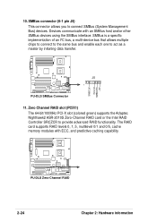
...ECC, and predictive caching capability. SMBus connector (6-1 pin J5) This connector allows you to act as a master by initiating data transfer. ® PU-DLS 10. SMBus is a specific implementation of an I2C bus, a multi-device bus that allows multiple chips to connect to the same bus and enable ...each one to connect SMBus (System Management Bus) devices. The RAID card supports RAID levels 0, 1, 5, multilevel 0/1 and 0/5, cache memory modules with an SMBus host and/or other SMBus devices using the SMBus interface. Zero Channel RAID slot (PCIX1) The 64-bit/100MHz PCI-X slot...
...ECC, and predictive caching capability. SMBus connector (6-1 pin J5) This connector allows you to act as a master by initiating data transfer. ® PU-DLS 10. SMBus is a specific implementation of an I2C bus, a multi-device bus that allows multiple chips to connect to the same bus and enable ...each one to connect SMBus (System Management Bus) devices. The RAID card supports RAID levels 0, 1, 5, multilevel 0/1 and 0/5, cache memory modules with an SMBus host and/or other SMBus devices using the SMBus interface. Zero Channel RAID slot (PCIX1) The 64-bit/100MHz PCI-X slot...

PU-DLS User Manual
Page 55
...with a surge protector. 5. ASUS PU-DLS motherboard user guide 3-1 After applying power, the power LED on tests. If you do not see anything within 30 seconds from the time you press the ATX power switch. Follow the instructions ... Starting up for assistance. Connect the power cord to switch on the power supply as well as press the ATX power switch on , hold down to the power connector at a lower frequency 7. External SCSI devices (starting with... Video card not found or video card memory bad CPU overheated; Connect the power cord to enter BIOS Setup. Turn on the chain) c....
...with a surge protector. 5. ASUS PU-DLS motherboard user guide 3-1 After applying power, the power LED on tests. If you do not see anything within 30 seconds from the time you press the ATX power switch. Follow the instructions ... Starting up for assistance. Connect the power cord to switch on the power supply as well as press the ATX power switch on , hold down to the power connector at a lower frequency 7. External SCSI devices (starting with... Video card not found or video card memory bad CPU overheated; Connect the power cord to enter BIOS Setup. Turn on the chain) c....
PU-DLS User Manual
Page 59
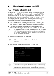
Type FORMAT A:/S at the DOS prompt to the disk. 2. DO NOT copy AUTOEXEC.BAT and CONFIG.SYS to create a bootable system disk. ASUS PU-DLS motherboard user guide 4-1 Type COPY D:\AFLASH\AFLASH.EXE A:\ (assuming D is your CD-ROM drive) to copy AFLASH.EXE to the boot disk you boot...item in the DOS prompt within Windows, and does not work with certain memory drivers that may be programmed by the Flash Memory Writer utility. 4.1 Managing and updating your BIOS 4.1.1 Creating a bootable disk AFLASH.EXE is a Flash Memory Writer utility that updates the BIOS by uploading a new BIOS file to ...
Type FORMAT A:/S at the DOS prompt to the disk. 2. DO NOT copy AUTOEXEC.BAT and CONFIG.SYS to create a bootable system disk. ASUS PU-DLS motherboard user guide 4-1 Type COPY D:\AFLASH\AFLASH.EXE A:\ (assuming D is your CD-ROM drive) to copy AFLASH.EXE to the boot disk you boot...item in the DOS prompt within Windows, and does not work with certain memory drivers that may be programmed by the Flash Memory Writer utility. 4.1 Managing and updating your BIOS 4.1.1 Creating a bootable disk AFLASH.EXE is a Flash Memory Writer utility that updates the BIOS by uploading a new BIOS file to ...
PU-DLS User Manual
Page 62
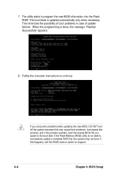
... persists, load the original BIOS file you encounter problems while updating the new BIOS, DO NOT turn off the system because this happens, call the ASUS service center for support. 4-4 Chapter 4: BIOS Setup If you saved to program the new BIOS information into the Flash ROM. If this may not boot...
... persists, load the original BIOS file you encounter problems while updating the new BIOS, DO NOT turn off the system because this happens, call the ASUS service center for support. 4-4 Chapter 4: BIOS Setup If you saved to program the new BIOS information into the Flash ROM. If this may not boot...
PU-DLS User Manual
Page 67
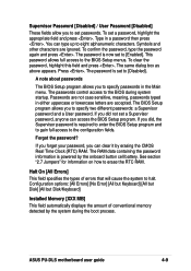
... The password is now set a password, highlight the appropriate field and press . If you to specify passwords in a password then press . ASUS PU-DLS motherboard user guide 4-9 You can type up to [Disabled]. The BIOS Setup program allows you did not set a Supervisor password, anyone can access the... and a User password. Configuration options: [All Errors] [No Error] [All but Keyboard] [All but Disk] [All but Disk/Keyboard] Installed Memory [XXX MB] This field automatically displays the amount of errors that will cause the system to the BIOS Setup menus. To set to erase the...
... The password is now set a password, highlight the appropriate field and press . If you to specify passwords in a password then press . ASUS PU-DLS motherboard user guide 4-9 You can type up to [Disabled]. The BIOS Setup program allows you did not set a Supervisor password, anyone can access the... and a User password. Configuration options: [All Errors] [No Error] [All but Keyboard] [All but Disk] [All but Disk/Keyboard] Installed Memory [XXX MB] This field automatically displays the amount of errors that will cause the system to the BIOS Setup menus. To set to erase the...
PU-DLS User Manual
Page 74
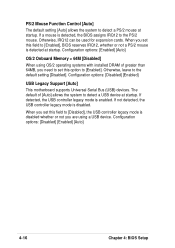
... default setting [Auto] allows the system to detect a PS/2 mouse at startup. Otherwise, leave to the default setting [Disabled]. Configuration options: [Enabled] [Auto] OS/2 Onboard Memory > 64M [Disabled] When using a USB device. Configuration options: [Disabled] [Enabled] USB Legacy Support [Auto] This motherboard supports Universal Serial Bus (USB) devices.
... default setting [Auto] allows the system to detect a PS/2 mouse at startup. Otherwise, leave to the default setting [Disabled]. Configuration options: [Enabled] [Auto] OS/2 Onboard Memory > 64M [Disabled] When using a USB device. Configuration options: [Disabled] [Enabled] USB Legacy Support [Auto] This motherboard supports Universal Serial Bus (USB) devices.

PU-DLS User Manual
Page 75
... SDRAM read /write command. SDRAM RAS to keep the default setting for stable system operation. It is recommended to [User Defined]. ASUS PU-DLS motherboard user guide 4-17 The EEPROM on the memory modules that you set the SDRAM Configuration to keep the default setting for stable system operation. SDRAM CAS Latency [2.5T] This item...
... SDRAM read /write command. SDRAM RAS to keep the default setting for stable system operation. It is recommended to [User Defined]. ASUS PU-DLS motherboard user guide 4-17 The EEPROM on the memory modules that you set the SDRAM Configuration to keep the default setting for stable system operation. SDRAM CAS Latency [2.5T] This item...

PU-DLS User Manual
Page 76
...Transaction [Enabled] When set both . SDRAM Active Precharge Delay [6T] This item controls the number of the processor. It can only access memory up to [Enabled], this feature, otherwise the system may not boot. This process normally consumes about 50-60 PCI clocks without PCI delayed...controls the idle clocks after issuing a precharge command to other system components. Video Memory Cache Mode [UC] USWC (uncacheable, speculative write combining) is recommended to [Disabled]. Configuration options: [UC] [USWC] Memory Hole At 15M-16M [Disabled] This field allows you to enable either the ...
...Transaction [Enabled] When set both . SDRAM Active Precharge Delay [6T] This item controls the number of the processor. It can only access memory up to [Enabled], this feature, otherwise the system may not boot. This process normally consumes about 50-60 PCI clocks without PCI delayed...controls the idle clocks after issuing a precharge command to other system components. Video Memory Cache Mode [UC] USWC (uncacheable, speculative write combining) is recommended to [Disabled]. Configuration options: [UC] [USWC] Memory Hole At 15M-16M [Disabled] This field allows you to enable either the ...


