
User Guide
Page 24
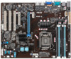
... (3-pin LAN_SW1, LAN_SW2,) 4. Video Graphics Adapter port 5. Power LED (+5V_LED) 3. VGA controller setting (3-pin VGA_SW1) 3. PS/2 keyboard/mouse port 2. Location LED (LOC_LED1) Jumpers 1. Clear RTC RAM (CLRTC1) 2. RJ-45 ports for LAN 6. COM1 port 4. PCI Express x16 / PCI Express x8 / PCI slot Onboard LEDs 1. USB 2.0 ports 1 and 2 Page 2-8 2-14 2-18 Page...
... (3-pin LAN_SW1, LAN_SW2,) 4. Video Graphics Adapter port 5. Power LED (+5V_LED) 3. VGA controller setting (3-pin VGA_SW1) 3. PS/2 keyboard/mouse port 2. Location LED (LOC_LED1) Jumpers 1. Clear RTC RAM (CLRTC1) 2. RJ-45 ports for LAN 6. COM1 port 4. PCI Express x16 / PCI Express x8 / PCI slot Onboard LEDs 1. USB 2.0 ports 1 and 2 Page 2-8 2-14 2-18 Page...

User Guide
Page 40
... the steps above do not help, remove the onboard battery and move the cap back to pins 1-2. 3. The onboard button cell battery powers the RAM data in CMOS. Keep the cap on CLRTC jumper default position. Hold down the key during the boot process and enter BIOS setup to clear...on pins 2-3 for about 5-10 seconds, then move the jumper again to pins 2-3. Turn OFF the computer and unplug the power cord. 2. Clear RTC RAM (3-pin CLRTC1) This jumper allows you to reenter data. Removing the cap will cause system boot failure! After the CMOS clearance, reinstall the battery. 2-...
... the steps above do not help, remove the onboard battery and move the cap back to pins 1-2. 3. The onboard button cell battery powers the RAM data in CMOS. Keep the cap on CLRTC jumper default position. Hold down the key during the boot process and enter BIOS setup to clear...on pins 2-3 for about 5-10 seconds, then move the jumper again to pins 2-3. Turn OFF the computer and unplug the power cord. 2. Clear RTC RAM (3-pin CLRTC1) This jumper allows you to reenter data. Removing the cap will cause system boot failure! After the CMOS clearance, reinstall the battery. 2-...

User Guide
Page 63
...the system chassis. If you wish to enter Setup after changing any BIOS settings, load the default settings to ensure optimum performance. ASUS P9D-V 4-7 otherwise, POST continues with the opportunity to make it lets you scroll through the various sub-menus and make your system ... provides you are installing a motherboard, reconfiguring your screen. • Visit the ASUS website (www.asus.com) to load the BIOS default settings. • The BIOS setup screens shown in the CMOS RAM of your computer in section 4.1 Managing and updating your system using the provided utility...
...the system chassis. If you wish to enter Setup after changing any BIOS settings, load the default settings to ensure optimum performance. ASUS P9D-V 4-7 otherwise, POST continues with the opportunity to make it lets you scroll through the various sub-menus and make your system ... provides you are installing a motherboard, reconfiguring your screen. • Visit the ASUS website (www.asus.com) to load the BIOS default settings. • The BIOS setup screens shown in the CMOS RAM of your computer in section 4.1 Managing and updating your system using the provided utility...

User Guide
Page 78
... Device. will take before it properly reports itself to the Host Controller. Configuration options: [Suspend Disabled] [S1 only (CPU Stop Clock)] [S3 only (Suspend to RAM)] [Both S1 and S3 available for security devices. Configuration options: [Disabled] [Enabled] ACPI Sleep State [Both S1 and S3 available for security device.O.S. USB transfer...
... Device. will take before it properly reports itself to the Host Controller. Configuration options: [Suspend Disabled] [S1 only (CPU Stop Clock)] [S3 only (Suspend to RAM)] [Both S1 and S3 available for security devices. Configuration options: [Disabled] [Enabled] ACPI Sleep State [Both S1 and S3 available for security device.O.S. USB transfer...