
User Manual
Page 23
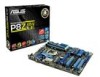
... module) DDR3 DIMM_B2 (64bit, 240-pin module) EATXPWR 30.5cm(12.0in) LGA1155 USB3_12 MemOK! 6 DRAM_LED LAN1_USB12 AUDIO CHA_FAN1 PWR_FAN P8Z68-V LE AAFP PCIEX1_1 Lithium Cell CMOS Power ASM 1042 PCIEX16_1 1 USB3_34 7 ASM 1042 RTL 8111E Super I/O PCIEX1_2 TPU PCI1 PCIEX16_2 Intel®...RAM (3-pin CLRTC) 1-26 1-17 . 13. Intel® Z68 Serial ATA 3.0 Gb/s connectors (7-pin SATA3G_1-4 [blue]) 1-30 18. USB connectors (10-1 pin USB5~12) 1-31 1-37 14 TPU switch 1-36 6. Intel® CPU socket 4. Front panel audio connector (10-1 pin AAFP) 1-29 ASUS P8Z68-V LE...
... module) DDR3 DIMM_B2 (64bit, 240-pin module) EATXPWR 30.5cm(12.0in) LGA1155 USB3_12 MemOK! 6 DRAM_LED LAN1_USB12 AUDIO CHA_FAN1 PWR_FAN P8Z68-V LE AAFP PCIEX1_1 Lithium Cell CMOS Power ASM 1042 PCIEX16_1 1 USB3_34 7 ASM 1042 RTL 8111E Super I/O PCIEX1_2 TPU PCI1 PCIEX16_2 Intel®...RAM (3-pin CLRTC) 1-26 1-17 . 13. Intel® Z68 Serial ATA 3.0 Gb/s connectors (7-pin SATA3G_1-4 [blue]) 1-30 18. USB connectors (10-1 pin USB5~12) 1-31 1-37 14 TPU switch 1-36 6. Intel® CPU socket 4. Front panel audio connector (10-1 pin AAFP) 1-29 ASUS P8Z68-V LE...

User Manual
Page 38
... cap on pins 2-3 for about 5-10 seconds, then move the jumper again to default values. 1-26 Chapter 1: Product introduction P8Z68-V LE CLRTC 12 23 Normal (Default) P8Z68-V LE Clear RTC RAM Clear RTC To erase the RTC RAM: 1. After clearing the CMOS, reinstall the battery. • You do not help, remove the onboard battery and move...
... cap on pins 2-3 for about 5-10 seconds, then move the jumper again to default values. 1-26 Chapter 1: Product introduction P8Z68-V LE CLRTC 12 23 Normal (Default) P8Z68-V LE Clear RTC RAM Clear RTC To erase the RTC RAM: 1. After clearing the CMOS, reinstall the battery. • You do not help, remove the onboard battery and move...

User Manual
Page 57
.... Chapter 2: BIOS information 2-7 Entering BIOS Setup after POST To enter BIOS Setup after changing any BIOS settings, load the default settings to erase the RTC RAM. • The BIOS setup program does not support the bluetooth devices. The BIOS screens include navigation keys and brief online help to guide you failed...
.... Chapter 2: BIOS information 2-7 Entering BIOS Setup after POST To enter BIOS Setup after changing any BIOS settings, load the default settings to erase the RTC RAM. • The BIOS setup program does not support the bluetooth devices. The BIOS screens include navigation keys and brief online help to guide you failed...

User Manual
Page 61
...an overview of the BIOS Setup program. Chapter 2: BIOS information 2-11 See section 1.9 Jumpers for information on how to erase the RTC RAM. • The Administrator or User Password items on top of the screen show Installed. After you set a password, these items show the... Item Enter: Select +/-: Change Opt. 2.3.1 System Language [English] Allows you have forgotten your BIOS password, erase the CMOS Real Time Clock (RTC) RAM to clear the BIOS password. Configuration options: [English] 2.3.2 System Date [Day xx/xx/xxxx] Allows you to set the system date. 2.3.3 System Time...
...an overview of the BIOS Setup program. Chapter 2: BIOS information 2-11 See section 1.9 Jumpers for information on how to erase the RTC RAM. • The Administrator or User Password items on top of the screen show Installed. After you set a password, these items show the... Item Enter: Select +/-: Change Opt. 2.3.1 System Language [English] Allows you have forgotten your BIOS password, erase the CMOS Real Time Clock (RTC) RAM to clear the BIOS password. Configuration options: [English] 2.3.2 System Date [Day xx/xx/xxxx] Allows you to set the system date. 2.3.3 System Time...


