
User Manual
Page 4
... up for the first time 2-42 2.11 Turning off the computer 2-42 Chapter 3: BIOS setup 3.1 Knowing BIOS 3-1 3.2 Updating BIOS 3-1 3.2.1 ASUS Update utility 3-1 3.2.2 ASUS EZ Flash 2 utility 3-5 3.2.3 ASUS CrashFree BIOS 3 utility 3-6 3.3 BIOS setup program 3-6 Entering BIOS Setup at startup 3-6 Entering BIOS Setup after POST 3-6 3.3.1 BIOS menu screen 3-7...3.5.4 CPU Ratio Setting 3-14 iv Contents 2.6 Onboard switch 2-24 2.7 Jumpers...2-25 2.8 Connectors 2-27 2.8.1 Rear panel connectors 2-27 2.8.2 Audio I/O connections 2-28 2.8.3 Internal connectors 2-31 2.8.4.
... up for the first time 2-42 2.11 Turning off the computer 2-42 Chapter 3: BIOS setup 3.1 Knowing BIOS 3-1 3.2 Updating BIOS 3-1 3.2.1 ASUS Update utility 3-1 3.2.2 ASUS EZ Flash 2 utility 3-5 3.2.3 ASUS CrashFree BIOS 3 utility 3-6 3.3 BIOS setup program 3-6 Entering BIOS Setup at startup 3-6 Entering BIOS Setup after POST 3-6 3.3.1 BIOS menu screen 3-7...3.5.4 CPU Ratio Setting 3-14 iv Contents 2.6 Onboard switch 2-24 2.7 Jumpers...2-25 2.8 Connectors 2-27 2.8.1 Rear panel connectors 2-27 2.8.2 Audio I/O connections 2-28 2.8.3 Internal connectors 2-31 2.8.4.

User Manual
Page 19
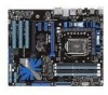
ASUS Q-Design enhances your motherboard against static electricity and shields it against Electronic Magnetic Interference (EMI). Profile Conveniently restore or load multiple BIOS settings Freely share and distribute favorite overclocking settings. Simply launch this tool and update BIOS from a USB flash drive before entering the OS. ASUS Q-Connector Make connection quick and accurate! ASUS P7P55D 1-5 All of...
ASUS Q-Design enhances your motherboard against static electricity and shields it against Electronic Magnetic Interference (EMI). Profile Conveniently restore or load multiple BIOS settings Freely share and distribute favorite overclocking settings. Simply launch this tool and update BIOS from a USB flash drive before entering the OS. ASUS Q-Connector Make connection quick and accurate! ASUS P7P55D 1-5 All of...
User Manual
Page 48
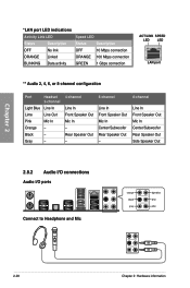
... Link LED Status Description OFF No link ORANGE Linked BLINKING Data activity Speed LED Status Description OFF 10 Mbps connection ORANGE 100 Mbps connection GREEN 1 Gbps connection ACT/LINK SPEED LED LED LAN port ** Audio 2, 4, 6, or 8-channel configuration Port Headset 2-channel Light Blue Line In Lime Line Out Pink Mic In ... Center/Subwoofer Rear Speaker Out - 8-channel Line In Front Speaker Out Mic In Center/Subwoofer Rear Speaker Out Side Speaker Out 2.8.2 Audio I/O connections Audio I/O ports Connect to Headphone and Mic 2-28 Chapter 2: Hardware information
... Link LED Status Description OFF No link ORANGE Linked BLINKING Data activity Speed LED Status Description OFF 10 Mbps connection ORANGE 100 Mbps connection GREEN 1 Gbps connection ACT/LINK SPEED LED LED LAN port ** Audio 2, 4, 6, or 8-channel configuration Port Headset 2-channel Light Blue Line In Lime Line Out Pink Mic In ... Center/Subwoofer Rear Speaker Out - 8-channel Line In Front Speaker Out Mic In Center/Subwoofer Rear Speaker Out Side Speaker Out 2.8.2 Audio I/O connections Audio I/O ports Connect to Headphone and Mic 2-28 Chapter 2: Hardware information
User Manual
Page 51
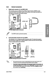
... the back of the motherboard's high-definition audio capability. if you connect a high-definition front panel audio module to this connector, set to this connector. • We recommend that supports either HD Audio or legacy AC`97 audio standard. 2.8.3 Internal connectors 1. Front panel audio connector (10-1 pin AAFP) This connector is purchased separately. 2. ASUS P7P55D 2-31 Chapter 2 The S/PDIF...
... the back of the motherboard's high-definition audio capability. if you connect a high-definition front panel audio module to this connector, set to this connector. • We recommend that supports either HD Audio or legacy AC`97 audio standard. 2.8.3 Internal connectors 1. Front panel audio connector (10-1 pin AAFP) This connector is purchased separately. 2. ASUS P7P55D 2-31 Chapter 2 The S/PDIF...
User Manual
Page 55
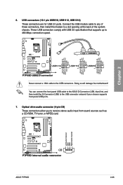
Chapter 2 6. Doing so will damage the motherboard! You can connect the front panel USB cable to the ASUS Q-Connector (USB, blue) first, and then install the Q-Connector (USB) to receive stereo audio input from sound sources such as a CD-ROM, TV tuner, or MPEG card. USB connectors (10-1 ...USB 2.0 ports. Optical drive audio connector (4-pin CD) These connectors allow you to the USB connector onboard if your chassis supports front panel USB ports. 7. Never connect a 1394 cable to a slot opening at the back of the system chassis. ASUS P7P55D 2-35 Connect the USB module cable to ...
Chapter 2 6. Doing so will damage the motherboard! You can connect the front panel USB cable to the ASUS Q-Connector (USB, blue) first, and then install the Q-Connector (USB) to receive stereo audio input from sound sources such as a CD-ROM, TV tuner, or MPEG card. USB connectors (10-1 ...USB 2.0 ports. Optical drive audio connector (4-pin CD) These connectors allow you to the USB connector onboard if your chassis supports front panel USB ports. 7. Never connect a 1394 cable to a slot opening at the back of the system chassis. ASUS P7P55D 2-35 Connect the USB module cable to ...


