
User Manual
Page 9
... the power cables are connected. If you are unplugged. • Seek professional assistance before using the product, ensure all the manuals that the battery should not be placed in municipal waste. This symbol of parts and recycling. ix If possible, disconnect all ...; Place the product on a stable surface. • If you add a device. • Before connecting or removing signal cables from the motherboard, ensure that the product (electrical and electronic equipment) should not be placed in municipal waste. Safety information Electrical safety • To prevent electrical...
... the power cables are connected. If you are unplugged. • Seek professional assistance before using the product, ensure all the manuals that the battery should not be placed in municipal waste. This symbol of parts and recycling. ix If possible, disconnect all ...; Place the product on a stable surface. • If you add a device. • Before connecting or removing signal cables from the motherboard, ensure that the product (electrical and electronic equipment) should not be placed in municipal waste. Safety information Electrical safety • To prevent electrical...
User Manual
Page 37
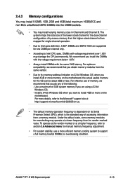
... over 1.65V may damage the CPU permanently. ASUS P7F7-E WS Supercomputer 2-13 The system maps the total size of accessing information from a memory module. For effective use a more on its Serial Presence Detect (SPD), which is dependent on the motherboard. Any excess memory from the same vendor. ...ECC unbuffered DDR3 DIMMs into the DIMM sockets. • You may operate at a higher frequency, refer to section 3.6 Advanced menu for manual memory frequency adjustment. • For system stability, use of the following: - To operate at the vendor-marked or at a lower frequency...
... over 1.65V may damage the CPU permanently. ASUS P7F7-E WS Supercomputer 2-13 The system maps the total size of accessing information from a memory module. For effective use a more on its Serial Presence Detect (SPD), which is dependent on the motherboard. Any excess memory from the same vendor. ...ECC unbuffered DDR3 DIMMs into the DIMM sockets. • You may operate at a higher frequency, refer to section 3.6 Advanced menu for manual memory frequency adjustment. • For system stability, use of the following: - To operate at the vendor-marked or at a lower frequency...
User Manual
Page 70
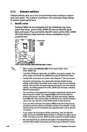
... that are incompaible with ones recommended in the Memory QVL (Qualified Vendors Lists) in this user manual or on the ASUS website at www.asus.com after using the MemOK! It takes about 5- 10 seconds. • If your system ... and replace DIMMs during POST reminding you download and update to the latest BIOS version from the ASUS website at www.asus.com. • If you to fine-tune performance when working on the computer. switch to ... the DIMM before using the MemOK! Replace the DIMMs with the motherboard may cause system boot failure, and the DIAG_DRAM LED near the MemOK!
... that are incompaible with ones recommended in the Memory QVL (Qualified Vendors Lists) in this user manual or on the ASUS website at www.asus.com after using the MemOK! It takes about 5- 10 seconds. • If your system ... and replace DIMMs during POST reminding you download and update to the latest BIOS version from the ASUS website at www.asus.com. • If you to fine-tune performance when working on the computer. switch to ... the DIMM before using the MemOK! Replace the DIMMs with the motherboard may cause system boot failure, and the DIAG_DRAM LED near the MemOK!

User Manual
Page 91
... Ratio Setting [22.0] Intel(R) SpeedStep(TM) Tech [Enabled] Intel(R) TurboMode tech [Enabled] Xtreme Phase Full Power Mode [Auto] DRAM Frequency [Auto] QPI Frequency [Auto] ASUS/3rd Party UI Priority [ASUS Utility] OC Tuner Start auto tuning [Turbo Profile] DRAM Timing Control Warning: this function belongs to Manual after you install on the motherboard. ASUS P7F7-E WS Supercomputer 3-15
... Ratio Setting [22.0] Intel(R) SpeedStep(TM) Tech [Enabled] Intel(R) TurboMode tech [Enabled] Xtreme Phase Full Power Mode [Auto] DRAM Frequency [Auto] QPI Frequency [Auto] ASUS/3rd Party UI Priority [ASUS Utility] OC Tuner Start auto tuning [Turbo Profile] DRAM Timing Control Warning: this function belongs to Manual after you install on the motherboard. ASUS P7F7-E WS Supercomputer 3-15

User Manual
Page 92
... of CPU overclocking options to set the profile(s) supported by adjusting BCLK frequency. The valid value ranges differently according to [Manual] after selecting a CPU level. Select either one DIMM on the motherboard. Overclocks DRAM frequency by your memory module(s) for the system. Use the and keys to DRAM frequency, DRAM timing and...
... of CPU overclocking options to set the profile(s) supported by adjusting BCLK frequency. The valid value ranges differently according to [Manual] after selecting a CPU level. Select either one DIMM on the motherboard. Overclocks DRAM frequency by your memory module(s) for the system. Use the and keys to DRAM frequency, DRAM timing and...

User Manual
Page 108
... [Silent] to minimize the fan speed for quiet CPU fan operation. [Turbo] Set to [Turbo] to achieve maximum CPU fan speed. [Manual] Set to [Manual] to display the detected temperatures. CPU Q-Fan Control [Disabled] [Disabled] Disables the CPU Q-Fan control feature. [Enabled] Enables the CPU ...;º�C�/x�x�x��º�F�] The onboard hardware monitor automatically detects and displays the CPU and motherboard temperatures. CPU Fan Profile [Standard] This item appears only when you enable the CPU Q-Fan Control feature and allows you...
... [Silent] to minimize the fan speed for quiet CPU fan operation. [Turbo] Set to [Turbo] to achieve maximum CPU fan speed. [Manual] Set to [Manual] to display the detected temperatures. CPU Q-Fan Control [Disabled] [Disabled] Disables the CPU Q-Fan control feature. [Enabled] Enables the CPU ...;º�C�/x�x�x��º�F�] The onboard hardware monitor automatically detects and displays the CPU and motherboard temperatures. CPU Fan Profile [Standard] This item appears only when you enable the CPU Q-Fan Control feature and allows you...
User Manual
Page 140
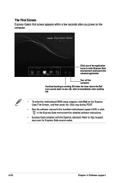
Refer to zero (0); click to immediately enter existing OS • To enter the motherboard BIOS setup program, click Exit on the computer. asus.com for detailed software instructions. • Express Gate complies with the OpenGL standard. Click any of the application icons to enter Express Gate ...appears within a few seconds after you power on the Express Gate First Screen, and then press the key during POST. • See the software manual in the bundled motherboard support DVD or click in the Express Gate environment for Express Gate source codes. 4-20 Chapter 4: Software support
Refer to zero (0); click to immediately enter existing OS • To enter the motherboard BIOS setup program, click Exit on the computer. asus.com for detailed software instructions. • Express Gate complies with the OpenGL standard. Click any of the application icons to enter Express Gate ...appears within a few seconds after you power on the Express Gate First Screen, and then press the key during POST. • See the software manual in the bundled motherboard support DVD or click in the Express Gate environment for Express Gate source codes. 4-20 Chapter 4: Software support

User Manual
Page 141
... monitor the power phase loading and temperature in the Advanced menu to the optical drive. Save BIOS settings and restart the computer. ASUS P7F7-E WS Supercomputer 4-21 With T.Probe enabled, the temperature of the power phase gradually levels to the center AVG (average) area. The temperature of...allowing components to complete installation. The number of BIOS settings Using ASUS T.Probe Click the T.Probe icon in real-time. Press during the Power-On Self Test (POST) to Chapter 3 of the motherboard user manual for detailed instructions of the phase bars varies depending on the...
... monitor the power phase loading and temperature in the Advanced menu to the optical drive. Save BIOS settings and restart the computer. ASUS P7F7-E WS Supercomputer 4-21 With T.Probe enabled, the temperature of the power phase gradually levels to the center AVG (average) area. The temperature of...allowing components to complete installation. The number of BIOS settings Using ASUS T.Probe Click the T.Probe icon in real-time. Press during the Power-On Self Test (POST) to Chapter 3 of the motherboard user manual for detailed instructions of the phase bars varies depending on the...

User Manual
Page 142
...EVO icon on the next system boot. TurboV EVO ASUS TurboV EVO introduces TurboV and Turbo Key-two powerful tools that came with the motherboard package. Click on the icon to overclock your customized overclocking settings and manually load the profile after Windows starts. Use the ... is correctly installed, you will not be kept on the Windows notification area. Refer to the software manual in ASUS TurboV (except for detailed software configuration. 4.4.1 Using ASUS TurboV ASUS TurboV allows you to display the TurboV EVO control panel. For system stability, all start-up values ...
...EVO icon on the next system boot. TurboV EVO ASUS TurboV EVO introduces TurboV and Turbo Key-two powerful tools that came with the motherboard package. Click on the icon to overclock your customized overclocking settings and manually load the profile after Windows starts. Use the ... is correctly installed, you will not be kept on the Windows notification area. Refer to the software manual in ASUS TurboV (except for detailed software configuration. 4.4.1 Using ASUS TurboV ASUS TurboV allows you to display the TurboV EVO control panel. For system stability, all start-up values ...

User Manual
Page 146
... Profile function to save your customized overclocking settings and manually load the profile after Windows starts. • EPU cannot run on the next system boot. To launch ASUS GPU Boost 1. Click More Setting from the motherboard support DVD. 2. Default Target settings settings Adjustment sliders... all changes without applying Applies all changes made in real-time without exiting and rebooting the OS. Install the ASUS GPU Boost driver from the motherboard support DVD. • For system stability, all changes immediately 4-26 Chapter 4: Software support Refer to High ...
... Profile function to save your customized overclocking settings and manually load the profile after Windows starts. • EPU cannot run on the next system boot. To launch ASUS GPU Boost 1. Click More Setting from the motherboard support DVD. 2. Default Target settings settings Adjustment sliders... all changes without applying Applies all changes made in real-time without exiting and rebooting the OS. Install the ASUS GPU Boost driver from the motherboard support DVD. • For system stability, all changes immediately 4-26 Chapter 4: Software support Refer to High ...

User Manual
Page 160
... GPU technology support Prepare two CrossFireX-ready graphics cards. 2. The graphics cards and the motherboard layout may vary with models, but the installation steps remain the same. 1. Ensure that the connector is firmly in this user manual for the locations of the PCIEX16 slots recommended for reference only. 5.1.3 Installing CrossFireX graphics cards...
... GPU technology support Prepare two CrossFireX-ready graphics cards. 2. The graphics cards and the motherboard layout may vary with models, but the installation steps remain the same. 1. Ensure that the connector is firmly in this user manual for the locations of the PCIEX16 slots recommended for reference only. 5.1.3 Installing CrossFireX graphics cards...

User Manual
Page 164
... Insert the two graphics card into the PCIEX16 slots. Prepare two SLI-ready graphics cards. 2. Ensure that the connector is firmly in this user manual for the locations of the PCIEX16 slots recommended for reference only. Align and firmly insert the SLI bridge connector to Chapter 2 in place. 5. SLI... bridge Goldfingers 5-6 Chapter 5: Multiple GPU technology support If your motherboard has more than two PCIEX16 slots, refer to the goldfingers on the slots. 4. The graphics cards and the...
... Insert the two graphics card into the PCIEX16 slots. Prepare two SLI-ready graphics cards. 2. Ensure that the connector is firmly in this user manual for the locations of the PCIEX16 slots recommended for reference only. Align and firmly insert the SLI bridge connector to Chapter 2 in place. 5. SLI... bridge Goldfingers 5-6 Chapter 5: Multiple GPU technology support If your motherboard has more than two PCIEX16 slots, refer to the goldfingers on the slots. 4. The graphics cards and the...

User Manual
Page 165
... into the PCIEX16 slots. If your motherboard has more than two PCIEX16 slots, refer to the three graphics cards separately. 6. Align and firmly insert the 3-Way SLI bridge connector to the graphics card. 3-Way SLI bridge ASUS P7F7-E WS Supercomputer 5-7 Ensure that the connector is firmly in this user manual for the locations of the PCIEX16...
... into the PCIEX16 slots. If your motherboard has more than two PCIEX16 slots, refer to the three graphics cards separately. 6. Align and firmly insert the 3-Way SLI bridge connector to the graphics card. 3-Way SLI bridge ASUS P7F7-E WS Supercomputer 5-7 Ensure that the connector is firmly in this user manual for the locations of the PCIEX16...


