
User Manual
Page 1
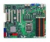
P7F-E Motherboard
P7F-E Motherboard

User Manual
Page 3
Contents Notices...vii Safety information viii About this guide ix Typography x P7F-E specifications summary xi Chapter 1: Product introduction 1.1 Welcome 1-3 1.2 Package contents 1-3 1.3 Serial number label 1-4 1.4 Special features 1-4 1.4.1 Product highlights 1-4 1.4.2 Innovative ASUS features 1-6 Chapter 2: Hardware information 2.1 Before you proceed 2-3 2.2 Motherboard overview 2-5 2.2.1 Placement direction 2-5 2.2.2 Screw holes 2-5 2.2.3 Motherboard layout 2-6 2.2.4 Layout contents 2-7 2.3 Central Processing Unit (CPU 2-9 2.3.1 Installing the CPU 2-9 2.3.2 Installing...
Contents Notices...vii Safety information viii About this guide ix Typography x P7F-E specifications summary xi Chapter 1: Product introduction 1.1 Welcome 1-3 1.2 Package contents 1-3 1.3 Serial number label 1-4 1.4 Special features 1-4 1.4.1 Product highlights 1-4 1.4.2 Innovative ASUS features 1-6 Chapter 2: Hardware information 2.1 Before you proceed 2-3 2.2 Motherboard overview 2-5 2.2.1 Placement direction 2-5 2.2.2 Screw holes 2-5 2.2.3 Motherboard layout 2-6 2.2.4 Layout contents 2-7 2.3 Central Processing Unit (CPU 2-9 2.3.1 Installing the CPU 2-9 2.3.2 Installing...
User Manual
Page 6
... and utilities installation 6-26 6.5.1 Running the support DVD 6-26 6.5.2 Drivers menu 6-26 6.5.3 Utilities menu 6-27 6.5.4 Make disk menu 6-27 6.5.5 Contact information 6-27 Appendix: Reference information A.1 P7F-E block diagram A-3 vi
... and utilities installation 6-26 6.5.1 Running the support DVD 6-26 6.5.2 Drivers menu 6-26 6.5.3 Utilities menu 6-27 6.5.4 Make disk menu 6-27 6.5.5 Contact information 6-27 Appendix: Reference information A.1 P7F-E block diagram A-3 vi
User Manual
Page 11
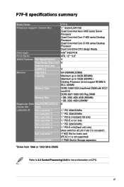
... Model Name P7F-E Processor Support / System Bus 1 * Socket LGA1156 Quad Core Intel Xeon 3400 series Server Processor Quad Core Intel Core i7-800 series Desktop Processor Quad Core Intel Core i5-700 series Desktop Processor Dual Core 32nm CPU design Ready Core Logic Intel® 3420 PCH Form Factor ATX, 12" * 9.6" ASUS Features...
... Model Name P7F-E Processor Support / System Bus 1 * Socket LGA1156 Quad Core Intel Xeon 3400 series Server Processor Quad Core Intel Core i7-800 series Desktop Processor Quad Core Intel Core i5-700 series Desktop Processor Dual Core 32nm CPU design Ready Core Logic Intel® 3420 PCH Form Factor ATX, 12" * 9.6" ASUS Features...
User Manual
Page 12
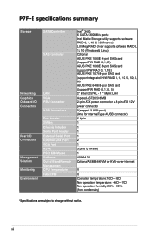
P7F-E specifications summary Storage Networking Graphics Onboard I/O Connectors Rear I/O Connectors Management Solution Monitoring Environment SATA Controller SAS Controller LAN VGA PSU Connector USB Connectors Fan Header ... 1068E 8-port SAS card (support FW RAID 0, 1, 1E) ASUS PIKE 1078 8-port SAS card (support integrated H/W RAID 0, 1, 10, 5, 50, 6, 60) ASUS PIKE 6480 8-port SAS card (Support FW RAID 0,1,10, 5) 2 * Intel 82574L + 1 * Mgmt LAN Aspeed AST2050 8MB 24-pin ATX power connector + 8-pin ATX 12V power connector 3 (support 5 USB port) (One for internal Type...
P7F-E specifications summary Storage Networking Graphics Onboard I/O Connectors Rear I/O Connectors Management Solution Monitoring Environment SATA Controller SAS Controller LAN VGA PSU Connector USB Connectors Fan Header ... 1068E 8-port SAS card (support FW RAID 0, 1, 1E) ASUS PIKE 1078 8-port SAS card (support integrated H/W RAID 0, 1, 10, 5, 50, 6, 60) ASUS PIKE 6480 8-port SAS card (Support FW RAID 0,1,10, 5) 2 * Intel 82574L + 1 * Mgmt LAN Aspeed AST2050 8MB 24-pin ATX power connector + 8-pin ATX 12V power connector 3 (support 5 USB port) (One for internal Type...
User Manual
Page 15
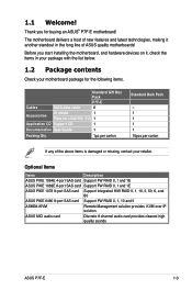
... User Guide 1 Packing Qty. 1pc per carton Standard Bulk Pack -1 1 1 1 10pcs per carton If any of the above items is damaged or missing, contact your motherboard package for the following items. Cables SATA data cable Standard Gift Box Pack P7F-E 6 Accessories IO shield 1 Plate for buying an ASUS® P7F-E motherboard!
... User Guide 1 Packing Qty. 1pc per carton Standard Bulk Pack -1 1 1 1 10pcs per carton If any of the above items is damaged or missing, contact your motherboard package for the following items. Cables SATA data cable Standard Gift Box Pack P7F-E 6 Accessories IO shield 1 Plate for buying an ASUS® P7F-E motherboard!
User Manual
Page 16
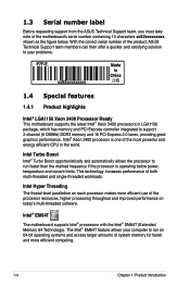
... below . The Intel® EM64T feature allows your problems. P7F-E xxS2xxxxxxxxx Made in China 合格 1.4 Special features 1.4.1 Product highlights Intel® LGA1156 Xeon 3400 Processor Ready This motherboard supports the latest Intel® Xeon 3400 processors in the world...PCI Express 2.0 lanes, providing great graphics performance. 1.3 Serial number label Before requesting support from the ASUS Technical Support team, you must take note of the motherboard's serial number containing 13 characters xxS2xxxxxxxxx shown as the figure below power, temperature and current limits....
... below . The Intel® EM64T feature allows your problems. P7F-E xxS2xxxxxxxxx Made in China 合格 1.4 Special features 1.4.1 Product highlights Intel® LGA1156 Xeon 3400 Processor Ready This motherboard supports the latest Intel® Xeon 3400 processors in the world...PCI Express 2.0 lanes, providing great graphics performance. 1.3 Serial number label Before requesting support from the ASUS Technical Support team, you must take note of the motherboard's serial number containing 13 characters xxS2xxxxxxxxx shown as the figure below power, temperature and current limits....
User Manual
Page 17
...and core frequency depending on USB 2.0. PCIe 2.0 This motherboard supports the latest PCIe 2.0 device for the memory is... to PCIe 1.0 devices. 82574L LAN Solution The motherboard comes with USB 1.1. This voltage reduction limits the...and reduced voltage requirements. DDR3 memory support The P7F-E supports UDIMM and RDIMM DDR3 memory that features... just 1.5V for your networking needs. USB 2.0 technology The motherboard implements the Universal Serial Bus (USB) 2.0 specification, dramatically increasing...motherboard supports the Serial ATA II 3 Gb/s technology through ...
...and core frequency depending on USB 2.0. PCIe 2.0 This motherboard supports the latest PCIe 2.0 device for the memory is... to PCIe 1.0 devices. 82574L LAN Solution The motherboard comes with USB 1.1. This voltage reduction limits the...and reduced voltage requirements. DDR3 memory support The P7F-E supports UDIMM and RDIMM DDR3 memory that features... just 1.5V for your networking needs. USB 2.0 technology The motherboard implements the Universal Serial Bus (USB) 2.0 specification, dramatically increasing...motherboard supports the Serial ATA II 3 Gb/s technology through ...
User Manual
Page 20
Chapter summary 2 2.1 Before you proceed 2-3 2.2 Motherboard overview 2-5 2.3 Central Processing Unit (CPU 2-9 2.4 System memory 2-15 2.5 Expansion slots 2-17 2.6 Jumpers 2-23 2.7 Connectors 2-27 ASUS P7F-E
Chapter summary 2 2.1 Before you proceed 2-3 2.2 Motherboard overview 2-5 2.3 Central Processing Unit (CPU 2-9 2.4 System memory 2-15 2.5 Expansion slots 2-17 2.6 Jumpers 2-23 2.7 Connectors 2-27 ASUS P7F-E
User Manual
Page 21
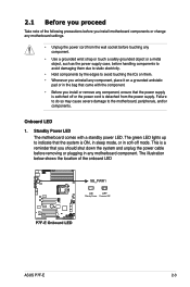
... such as the power supply case, before you install motherboard components or change any motherboard component. This is a reminder that you should shut down... the system and unplug the power cable before removing or plugging in soft-off or the power cord is ON, in sleep mode, or in any motherboard... settings. • Unplug the power cord from the power supply. Standby Power LED The motherboard comes with the ...motherboard, peripherals, and/or components. 2.1 Before you proceed Take note of the...
... such as the power supply case, before you install motherboard components or change any motherboard component. This is a reminder that you should shut down... the system and unplug the power cable before removing or plugging in soft-off or the power cord is ON, in sleep mode, or in any motherboard... settings. • Unplug the power cord from the power supply. Standby Power LED The motherboard comes with the ...motherboard, peripherals, and/or components. 2.1 Before you proceed Take note of the...

User Manual
Page 23
...DO NOT overtighten the screws! Doing so can cause you physical injury and damage motherboard components! 2.2.1 Placement direction When installing the motherboard, ensure that you install it in an ATX 1.1 compliant chassis. The edge with external ports goes to the rear part of...removing the motherboard. Place this side towards the rear of your chassis to do so can damage the motherboard. To optimize the motherboard features, we highly recommend that you install the motherboard, study the configuration of the chassis ASUS P7F-E 2-5 Ensure to the chassis. 2.2 Motherboard overview ...
...DO NOT overtighten the screws! Doing so can cause you physical injury and damage motherboard components! 2.2.1 Placement direction When installing the motherboard, ensure that you install it in an ATX 1.1 compliant chassis. The edge with external ports goes to the rear part of...removing the motherboard. Place this side towards the rear of your chassis to do so can damage the motherboard. To optimize the motherboard features, we highly recommend that you install the motherboard, study the configuration of the chassis ASUS P7F-E 2-5 Ensure to the chassis. 2.2 Motherboard overview ...
User Manual
Page 25
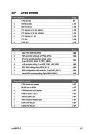
... Page 2-9 2-15 2-19 2-19 2-19 2-19 2-19 2-19 Page 2-23 2-24 2-24 2-25 2-25 2-26 2-26 Page 2-27 2-27 2-27 2-27 2-27 2-27 2-27 2-27 ASUS P7F-E 2-7 CPU sockets 2. CPU Fan and Chassis Fan control setting (3-pin CPUFAN_SEL1, CHAFAN_SEL1) 4. Serial (COM1) port 6.
... Page 2-9 2-15 2-19 2-19 2-19 2-19 2-19 2-19 Page 2-23 2-24 2-24 2-25 2-25 2-26 2-26 Page 2-27 2-27 2-27 2-27 2-27 2-27 2-27 2-27 ASUS P7F-E 2-7 CPU sockets 2. CPU Fan and Chassis Fan control setting (3-pin CPUFAN_SEL1, CHAFAN_SEL1) 4. Serial (COM1) port 6.

User Manual
Page 27
...PnP cap is missing, or if you are not bent. ASUS will shoulder the cost of repair only if the damage is released from incorrect CPU installation/removal, or misplacement/loss/ incorrect removal of the motherboard, ensure that the socket box is facing toward you and...pins, do not remove the PnP cap unless you see any damage to the PnP cap/socket contacts/motherboard components. ASUS P7F-E Load lever A B Retention tab 2-9 2.3 Central Processing Unit (CPU) The motherboard comes with a surface mount LGA1156 socket designed for the Intel® Xeon 3400 series Processors. •...
...PnP cap is missing, or if you are not bent. ASUS will shoulder the cost of repair only if the damage is released from incorrect CPU installation/removal, or misplacement/loss/ incorrect removal of the motherboard, ensure that the socket box is facing toward you and...pins, do not remove the PnP cap unless you see any damage to the PnP cap/socket contacts/motherboard components. ASUS P7F-E Load lever A B Retention tab 2-9 2.3 Central Processing Unit (CPU) The motherboard comes with a surface mount LGA1156 socket designed for the Intel® Xeon 3400 series Processors. •...

User Manual
Page 29
... toxic and inedible. B A C 8. Some heatsinks come with , ensuring that the front edge of the CPU that the heatsink will be in an even thin layer. ASUS P7F-E 2-11 If it gets into your eyes or touches your skin, wash it . 6. Apply some Thermal Interface Material to the exposed area of the load...
... toxic and inedible. B A C 8. Some heatsinks come with , ensuring that the front edge of the CPU that the heatsink will be in an even thin layer. ASUS P7F-E 2-11 If it gets into your eyes or touches your skin, wash it . 6. Apply some Thermal Interface Material to the exposed area of the load...

User Manual
Page 31
... monitoring errors can occur if you fail to connect the CPU fan connector! 3. Carefully remove the heatsink and fan assembly from the motherboard. ASUS P7F-E 2-13 DO NOT forget to plug this connector. 2.3.3 Uninstalling the CPU heatsink and fan To uninstall the CPU heatsink and fan: 1. ...Disconnect the CPU fan cable from B the connector on the motherboard labeled CPU_FAN. Rotate each fastener counterclockwise. 3. Connect the CPU fan cable to disengage the heatsink and fan assembly from the...
... monitoring errors can occur if you fail to connect the CPU fan connector! 3. Carefully remove the heatsink and fan assembly from the motherboard. ASUS P7F-E 2-13 DO NOT forget to plug this connector. 2.3.3 Uninstalling the CPU heatsink and fan To uninstall the CPU heatsink and fan: 1. ...Disconnect the CPU fan cable from B the connector on the motherboard labeled CPU_FAN. Rotate each fastener counterclockwise. 3. Connect the CPU fan cable to disengage the heatsink and fan assembly from the...
User Manual
Page 33
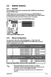
...Rank, Dual Rank 2 2 Unbuffered DDR3 1333 Single Rank, Dual Rank *Support Low Voltage DIMMs; **Down from the same vendor. DDR3 modules are not supported ASUS P7F-E 2-15 The figure illustrates the location of the DDR3 DIMM sockets: 2.4.2 Memory Configurations You may install 1 GB, 2 GB, 4 GB, 8 GB Registerd... six Double Data Rate 3 (DDR3) Dual Inline Memory Modules (DIMM) sockets. DO NOT combine RDIMM and UDIMM. • The motherboard supports x8 DRAM Only and x4 & x16 DRAM are developed for better performance with the same CAS latency. 2.4 System memory 2.4.1 Overview The...
...Rank, Dual Rank 2 2 Unbuffered DDR3 1333 Single Rank, Dual Rank *Support Low Voltage DIMMs; **Down from the same vendor. DDR3 modules are not supported ASUS P7F-E 2-15 The figure illustrates the location of the DDR3 DIMM sockets: 2.4.2 Memory Configurations You may install 1 GB, 2 GB, 4 GB, 8 GB Registerd... six Double Data Rate 3 (DDR3) Dual Inline Memory Modules (DIMM) sockets. DO NOT combine RDIMM and UDIMM. • The motherboard supports x8 DRAM Only and x4 & x16 DRAM are developed for better performance with the same CAS latency. 2.4 System memory 2.4.1 Overview The...
User Manual
Page 35
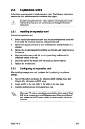
... in a chassis). 3. Keep the screw for the card. 2. Secure the card to use . 4. Remove the system unit cover (if your motherboard is completely seated on shared slots, ensure that the drivers support "Share IRQ" or that you physical injury and damage... motherboard components. 2.5.1 Installing an expansion card To install an expansion card: 1. See Chapter 4 for the expansion card. Otherwise, conflicts will arise between the two PCI groups, making the system unstable and the card inoperable. ASUS P7F-E 2-17 Replace the system cover. 2.5.2 ...
... in a chassis). 3. Keep the screw for the card. 2. Secure the card to use . 4. Remove the system unit cover (if your motherboard is completely seated on shared slots, ensure that the drivers support "Share IRQ" or that you physical injury and damage... motherboard components. 2.5.1 Installing an expansion card To install an expansion card: 1. See Chapter 4 for the expansion card. Otherwise, conflicts will arise between the two PCI groups, making the system unstable and the card inoperable. ASUS P7F-E 2-17 Replace the system cover. 2.5.2 ...

User Manual
Page 37
2.5.7 PCI Express x1 slot This slot supports PCI Express cards that comply with the PCI Express specifications. 2.5.8 PCI slots The PCI slot supports cards such as a LAN card, USB card, and other cards that comply with PCI 2.3 specifications. 2.5.9 PIKE slot The PIKE slot allows you to choose and change your needs. ASUS P7F-E 2-19 MIO PCIE slot PCIEx16 slot (x16 link) PCI slot PCIEx1 slot PCIEx16 slot (x8 link) PCI slots PIKE Interface The PIKE Interface is for ASUS PIKE RAID card only. Install an optional ASUS PIKE RAID card based on your preferred SAS solution easily.
2.5.7 PCI Express x1 slot This slot supports PCI Express cards that comply with the PCI Express specifications. 2.5.8 PCI slots The PCI slot supports cards such as a LAN card, USB card, and other cards that comply with PCI 2.3 specifications. 2.5.9 PIKE slot The PIKE slot allows you to choose and change your needs. ASUS P7F-E 2-19 MIO PCIE slot PCIEx16 slot (x16 link) PCI slot PCIEx1 slot PCIEx16 slot (x8 link) PCI slots PIKE Interface The PIKE Interface is for ASUS PIKE RAID card only. Install an optional ASUS PIKE RAID card based on your preferred SAS solution easily.

User Manual
Page 39
2.5.11 Installing i Button Follow the steps below to install an optional i Button on your motherboard. 1. Snap the I Button slot on the motherboard. 2. Orient and press the ASMB4 management card in place. ASUS P7F-E 2-21 You need to install I Button before using PIKE 1078 functions. 2.5.12 Installing ASMB4 management board Follow the steps below to install an optional ASMB4 management board on your motherboard. 1. Locate the BMC_FW1 header on the motherboard. 2. Locate the I Button in place.
2.5.11 Installing i Button Follow the steps below to install an optional i Button on your motherboard. 1. Snap the I Button slot on the motherboard. 2. Orient and press the ASMB4 management card in place. ASUS P7F-E 2-21 You need to install I Button before using PIKE 1078 functions. 2.5.12 Installing ASMB4 management board Follow the steps below to install an optional ASMB4 management board on your motherboard. 1. Locate the BMC_FW1 header on the motherboard. 2. Locate the I Button in place.
User Manual
Page 41
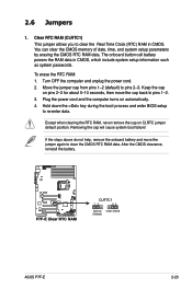
... battery and move the cap back to clear the Real Time Clock (RTC) RAM in CMOS, which include system setup information such as system passwords. ASUS P7F-E 2-23 The onboard button cell battery powers the RAM data in CMOS. Plug the power cord and the computer turns on CLRTC jumper default position...
... battery and move the cap back to clear the Real Time Clock (RTC) RAM in CMOS, which include system setup information such as system passwords. ASUS P7F-E 2-23 The onboard button cell battery powers the RAM data in CMOS. Plug the power cord and the computer turns on CLRTC jumper default position...