User Manual
Page 11
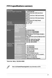
... Model Name P7F-E Processor Support / System Bus 1 * Socket LGA1156 Quad Core Intel Xeon 3400 series Server Processor Quad Core Intel Core i7-800 series Desktop Processor Quad Core Intel Core i5-700 series Desktop Processor Dual Core 32nm CPU design Ready Core Logic Intel® 3420 PCH Form Factor ATX, 12" * 9.6" ASUS Features...
... Model Name P7F-E Processor Support / System Bus 1 * Socket LGA1156 Quad Core Intel Xeon 3400 series Server Processor Quad Core Intel Core i7-800 series Desktop Processor Quad Core Intel Core i5-700 series Desktop Processor Dual Core 32nm CPU design Ready Core Logic Intel® 3420 PCH Form Factor ATX, 12" * 9.6" ASUS Features...
User Manual
Page 12
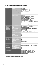
xii P7F-E specifications summary Storage Networking Graphics Onboard I/O Connectors Rear I/O Connectors Management Solution Monitoring Environment SATA Controller SAS Controller LAN VGA PSU Connector USB Connectors Fan Header ... 1068E 8-port SAS card (support FW RAID 0, 1, 1E) ASUS PIKE 1078 8-port SAS card (support integrated H/W RAID 0, 1, 10, 5, 50, 6, 60) ASUS PIKE 6480 8-port SAS card (Support FW RAID 0,1,10, 5) 2 * Intel 82574L + 1 * Mgmt LAN Aspeed AST2050 8MB 24-pin ATX power connector + 8-pin ATX 12V power connector 3 (support 5 USB port) (One for internal Type...
xii P7F-E specifications summary Storage Networking Graphics Onboard I/O Connectors Rear I/O Connectors Management Solution Monitoring Environment SATA Controller SAS Controller LAN VGA PSU Connector USB Connectors Fan Header ... 1068E 8-port SAS card (support FW RAID 0, 1, 1E) ASUS PIKE 1078 8-port SAS card (support integrated H/W RAID 0, 1, 10, 5, 50, 6, 60) ASUS PIKE 6480 8-port SAS card (Support FW RAID 0,1,10, 5) 2 * Intel 82574L + 1 * Mgmt LAN Aspeed AST2050 8MB 24-pin ATX power connector + 8-pin ATX 12V power connector 3 (support 5 USB port) (One for internal Type...

User Manual
Page 23
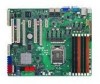
...ports goes to the rear part of the chassis ASUS P7F-E 2-5 Doing so can cause you physical injury and damage motherboard components! 2.2.1 Placement direction When installing the motherboard, ensure that you install it . To optimize the motherboard features, we highly recommend that you place it ... the correct orientation. Failure to do so can damage the motherboard. 2.2 Motherboard overview Before you install the motherboard, study the configuration of your chassis to ensure that the motherboard fits into it in an ATX 1.1 compliant chassis. Ensure to unplug the chassis power cord ...
...ports goes to the rear part of the chassis ASUS P7F-E 2-5 Doing so can cause you physical injury and damage motherboard components! 2.2.1 Placement direction When installing the motherboard, ensure that you install it . To optimize the motherboard features, we highly recommend that you place it ... the correct orientation. Failure to do so can damage the motherboard. 2.2 Motherboard overview Before you install the motherboard, study the configuration of your chassis to ensure that the motherboard fits into it in an ATX 1.1 compliant chassis. Ensure to unplug the chassis power cord ...

User Manual
Page 52
...boot up if the power is recommended when configuring a system with an SMBus host and/or other SMBus devices using the SMBus interface. 12. ATX power connectors (24-pin EATXPWR1, 8-pin EATX12V1) These connectors are designed to fit these connectors in only one orientation. The system may become ...unstable or may not boot up . • Use of a PSU with a higher power output is inadequate. • This motherboard supports ATX2.0 PSU or later version. • Ensure that your power supply unit (PSU) can provide at least the minimum power required by your system...
...boot up if the power is recommended when configuring a system with an SMBus host and/or other SMBus devices using the SMBus interface. 12. ATX power connectors (24-pin EATXPWR1, 8-pin EATX12V1) These connectors are designed to fit these connectors in only one orientation. The system may become ...unstable or may not boot up . • Use of a PSU with a higher power output is inadequate. • This motherboard supports ATX2.0 PSU or later version. • Ensure that your power supply unit (PSU) can provide at least the minimum power required by your system...
User Manual
Page 53
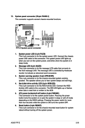
... is for the system power LED. Connect the HDD Activity LED cable to the HDD. 5. 13. ATX power button/soft-off the system power. Pressing the power button turns the system on the BIOS settings. ASUS P7F-E 2-35 Reset button (2-pin RESET) This 2-pin connector is for the chassis-mounted reset button for...
... is for the system power LED. Connect the HDD Activity LED cable to the HDD. 5. 13. ATX power button/soft-off the system power. Pressing the power button turns the system on the BIOS settings. ASUS P7F-E 2-35 Reset button (2-pin RESET) This 2-pin connector is for the chassis-mounted reset button for...

User Manual
Page 89
... [Enabled]. The computer cannot receive or transmit data until the computer and applications are fully running. This feature requires an ATX power supply that turns the system power on the +5VSB lead. ASUS P7F-E 4-31 System Time [12:30:30] Use the , or key to configure alarm time. Use the or key to...
... [Enabled]. The computer cannot receive or transmit data until the computer and applications are fully running. This feature requires an ATX power supply that turns the system power on the +5VSB lead. ASUS P7F-E 4-31 System Time [12:30:30] Use the , or key to configure alarm time. Use the or key to...

