User Manual
Page 4
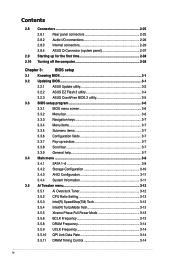
Contents 2.8 Connectors 2-25 2.8.1 Rear panel connectors 2-25 2.8.2 Audio I/O connections 2-26 2.8.3 Internal connectors 2-29 2.8.4 ASUS Q-Connector (system panel 2-37 2.9 Starting up for the first time 2-38 2.10 Turning off the computer 2-38 Chapter 3: BIOS setup 3.1 Knowing BIOS 3-1 3.2 Updating BIOS 3-1 3.2.1 ASUS Update utility 3-2 3.2.2 ASUS EZ Flash 2 utility 3-4 3.2.3 ASUS CrashFree BIOS 3 utility 3-5 3.3 BIOS setup program 3-6 3.3.1 BIOS menu screen 3-6 3.3.2 Menu...
Contents 2.8 Connectors 2-25 2.8.1 Rear panel connectors 2-25 2.8.2 Audio I/O connections 2-26 2.8.3 Internal connectors 2-29 2.8.4 ASUS Q-Connector (system panel 2-37 2.9 Starting up for the first time 2-38 2.10 Turning off the computer 2-38 Chapter 3: BIOS setup 3.1 Knowing BIOS 3-1 3.2 Updating BIOS 3-1 3.2.1 ASUS Update utility 3-2 3.2.2 ASUS EZ Flash 2 utility 3-4 3.2.3 ASUS CrashFree BIOS 3 utility 3-5 3.3 BIOS setup program 3-6 3.3.1 BIOS menu screen 3-6 3.3.2 Menu...

User Manual
Page 7
... radio noise emissions from that interference will not occur in a residential installation. Canadian Department of Communications. Check local regulations for connection of electronic products. This equipment has been tested and found to operate this equipment. REACH Complying with the REACH (Registration, ...determined by turning the equipment off and on a circuit different from digital apparatus set out in our products at ASUS REACH website at http://green.asus.com/english/REACH.htm. This symbol of the following two conditions: • This device may not cause harmful...
... radio noise emissions from that interference will not occur in a residential installation. Canadian Department of Communications. Check local regulations for connection of electronic products. This equipment has been tested and found to operate this equipment. REACH Complying with the REACH (Registration, ...determined by turning the equipment off and on a circuit different from digital apparatus set out in our products at ASUS REACH website at http://green.asus.com/english/REACH.htm. This symbol of the following two conditions: • This device may not cause harmful...

User Manual
Page 8
... stable surface. • If you encounter technical problems with the package. • Before using the product, ensure all cables are correctly connected and the power cables are not damaged. Safety information Electrical safety • To prevent electrical shock hazard, disconnect the power cable from the ..., ensure that the power cables for the devices are unplugged before the signal cables are using, contact your retailer. If you are connected. These devices could interrupt the grounding circuit. • Ensure that your area. Do not place the product in your power supply ...
... stable surface. • If you encounter technical problems with the package. • Before using the product, ensure all cables are correctly connected and the power cables are not damaged. Safety information Electrical safety • To prevent electrical shock hazard, disconnect the power cable from the ..., ensure that the power cables for the devices are unplugged before the signal cables are using, contact your retailer. If you are connected. These devices could interrupt the grounding circuit. • Ensure that your area. Do not place the product in your power supply ...
User Manual
Page 16
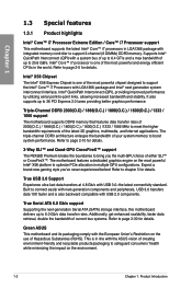
... in LGA1366 package with USB 3.0-the latest connectivity standard....to 36 PCI Express 2.0...to connect easily with LGA1366 package... and Intel® next generation system interconnect interface, Intel® QuickPath Interconnect (QPI), providing improved performance by utilizing serial point-to bring you 've never experienced before! Green ASUS This motherboard and its packaging comply with the ASUS vision of the latest 3D graphics, multimedia, and Internet applications. Intel® X58... support The P6X58D Premium breaks the ... max bandwidth of up ...174; X58 platform...
... in LGA1366 package with USB 3.0-the latest connectivity standard....to 36 PCI Express 2.0...to connect easily with LGA1366 package... and Intel® next generation system interconnect interface, Intel® QuickPath Interconnect (QPI), providing improved performance by utilizing serial point-to bring you 've never experienced before! Green ASUS This motherboard and its packaging comply with the ASUS vision of the latest 3D graphics, multimedia, and Internet applications. Intel® X58... support The P6X58D Premium breaks the ... max bandwidth of up ...174; X58 platform...
User Manual
Page 19
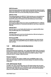
...freedom to overclock without using a bootable floppy disk or an OS-based utility. ASUS P6X58D Premium 1-5 The BIOS settings can be stored in different scenarios. Chapter 1 ASUS Q-Connector ASUS Q-Connector allows you to easily connect or disconnect the chassis front panel cables to select the language of your choice... chassis and clear the RTC data. Precision Tweaker 2 Allows you configure your system easier and faster. 1.3.3 ASUS exclusive overclocking features ASUS TurboV Feel the adrenaline rush of connecting the system panel cables one at a time and avoiding wrong cable...
...freedom to overclock without using a bootable floppy disk or an OS-based utility. ASUS P6X58D Premium 1-5 The BIOS settings can be stored in different scenarios. Chapter 1 ASUS Q-Connector ASUS Q-Connector allows you to easily connect or disconnect the chassis front panel cables to select the language of your choice... chassis and clear the RTC data. Precision Tweaker 2 Allows you configure your system easier and faster. 1.3.3 ASUS exclusive overclocking features ASUS TurboV Feel the adrenaline rush of connecting the system panel cables one at a time and avoiding wrong cable...

User Manual
Page 29
...if you fail to the connector on the motherboard. 2. B 3. Carefully remove the heatsink and fan assembly from the motherboard. Connect the CPU fan cable to plug this connector. 2.3.3 Uninstalling the CPU heatsink and fan To uninstall the CPU heatsink and fan:... at a time in a diagonal sequence to connect the CPU fan connector! Disconnect the CPU fan cable from the connector on the motherboard labeled CPU_FAN. Chapter 2 DO NOT forget to disengage the heatsink and fan assembly from the motherboard. Rotate each fastener counterclockwise. ASUS P6X58D Premium 2-9
...if you fail to the connector on the motherboard. 2. B 3. Carefully remove the heatsink and fan assembly from the motherboard. Connect the CPU fan cable to plug this connector. 2.3.3 Uninstalling the CPU heatsink and fan To uninstall the CPU heatsink and fan:... at a time in a diagonal sequence to connect the CPU fan connector! Disconnect the CPU fan cable from the connector on the motherboard labeled CPU_FAN. Chapter 2 DO NOT forget to disengage the heatsink and fan assembly from the motherboard. Rotate each fastener counterclockwise. ASUS P6X58D Premium 2-9
User Manual
Page 41
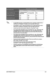
ASUS P6X58D Premium 2-21 See page 2-35 for details. • Connect a chassis fan to the motherboard connector labeled CHA_FAN1/2/3 when using multiple graphics cards for details. See page 2-33 for better thermal environment. See page 3-22 for 3-Way SLI or CrossFireX™ mode. • If you install a PCIe x16 graphics card on to the PCIe... the link width of PCIe x16_2 and PCIe x16_3 slots in BIOS settings. Chapter 2 VGA configuration Single VGA/PCIe card Dual VGA/PCIe card Triple VGA/PCIe card PCI Express operating mode PCIe x16_1 PCIe x16_2 PCIe x16_3 x16 (Recommend for...
ASUS P6X58D Premium 2-21 See page 2-35 for details. • Connect a chassis fan to the motherboard connector labeled CHA_FAN1/2/3 when using multiple graphics cards for details. See page 2-33 for better thermal environment. See page 3-22 for 3-Way SLI or CrossFireX™ mode. • If you install a PCIe x16 graphics card on to the PCIe... the link width of PCIe x16_2 and PCIe x16_3 slots in BIOS settings. Chapter 2 VGA configuration Single VGA/PCIe card Dual VGA/PCIe card Triple VGA/PCIe card PCI Express operating mode PCIe x16_1 PCIe x16_2 PCIe x16_3 x16 (Recommend for...

User Manual
Page 46
... Out - 8-channel Line In Front Speaker Out Mic In Center/Subwoofer Rear Speaker Out Side Speaker Out 2.8.2 Audio I/O connections Audio I/O ports Connect to Headphone and Mic 2-26 Chapter 2: Hardware information Chapter 2 * LAN port LED indications Activity Link LED Status Description ...OFF No link ORANGE Linked BLINKING Data activity Speed LED Status OFF ORANGE GREEN Description 10 Mbps connection 100 Mbps connection 1 Gbps connection ACT/LINK SPEED LED LED LAN port ** Audio 2, 4, 6, or 8-channel configuration Port Light Blue Lime Pink...
... Out - 8-channel Line In Front Speaker Out Mic In Center/Subwoofer Rear Speaker Out Side Speaker Out 2.8.2 Audio I/O connections Audio I/O ports Connect to Headphone and Mic 2-26 Chapter 2: Hardware information Chapter 2 * LAN port LED indications Activity Link LED Status Description ...OFF No link ORANGE Linked BLINKING Data activity Speed LED Status OFF ORANGE GREEN Description 10 Mbps connection 100 Mbps connection 1 Gbps connection ACT/LINK SPEED LED LED LAN port ** Audio 2, 4, 6, or 8-channel configuration Port Light Blue Lime Pink...

User Manual
Page 47
Chapter 2 Connect to Stereo Speakers Connect to 2.1 channel Speakers Connect to 4.1 channel Speakers ASUS P6X58D Premium 2-27
Chapter 2 Connect to Stereo Speakers Connect to 2.1 channel Speakers Connect to 4.1 channel Speakers ASUS P6X58D Premium 2-27

User Manual
Page 48
Connect to 5.1 channel Speakers Connect to 7.1 channel Speakers Chapter 2 2-28 Chapter 2: Hardware information
Connect to 5.1 channel Speakers Connect to 7.1 channel Speakers Chapter 2 2-28 Chapter 2: Hardware information
User Manual
Page 49
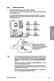
... optical disc drives. In Standard IDE mode, you intend to [AHCI]. The Serial ATA RAID feature is available only if you can connect Serial ATA boot/data hard disk drives to these connectors, set the Configure SATA as item in the BIOS to create a Serial ATA...connectors (7-pin SATA 1-6 [blue]) These connectors are using Windows® XP SP 2 or later version. • When using Serial ATA hard disk drives. ASUS P6X58D Premium 2-29 Chapter 2 • These connectors are set , refer to section 4.4 RAID configurations or the manual bundled in the motherboard support DVD. • ...
... optical disc drives. In Standard IDE mode, you intend to [AHCI]. The Serial ATA RAID feature is available only if you can connect Serial ATA boot/data hard disk drives to these connectors, set the Configure SATA as item in the BIOS to create a Serial ATA...connectors (7-pin SATA 1-6 [blue]) These connectors are using Windows® XP SP 2 or later version. • When using Serial ATA hard disk drives. ASUS P6X58D Premium 2-29 Chapter 2 • These connectors are set , refer to section 4.4 RAID configurations or the manual bundled in the motherboard support DVD. • ...
User Manual
Page 50
In Standard IDE mode, you can connect Serial ATA data hard disk drives to these connectors. • You must install Windows® XP Service Pack 2 or later versions before using Serial ATA ...
In Standard IDE mode, you can connect Serial ATA data hard disk drives to these connectors. • You must install Windows® XP Service Pack 2 or later versions before using Serial ATA ...

User Manual
Page 51
... cable to the USB connector onboard if your chassis supports front panel USB ports. Chapter 2 ASUS P6X58D Premium 2-31 Doing so will damage the motherboard! You can connect the front panel USB cable to the ASUS Q-Connector (USB, blue) first, and then install the Q-Connector (USB) to the USB connectors. These USB connectors comply with...
... cable to the USB connector onboard if your chassis supports front panel USB ports. Chapter 2 ASUS P6X58D Premium 2-31 Doing so will damage the motherboard! You can connect the front panel USB cable to the ASUS Q-Connector (USB, blue) first, and then install the Q-Connector (USB) to the USB connectors. These USB connectors comply with...
User Manual
Page 52
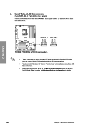
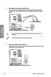
Never connect a USB cable to receive stereo audio input from sound sources such as a CD-ROM, TV tuner, or MPEG card. 2-32 Chapter 2: Hardware information Optical drive audio connector (4-pin CD) These connectors allow you to the IEEE 1394a connector. Chapter 2 4. Connect the IEEE 1394a module cable to this connector, then install the module to a slot opening at the back of the system chassis. Doing so will damage the motherboard! IEEE 1394a port connector (10-1 pin IE1394_2) This connector is purchased separately. 5. The IEEE 1394a module cable is for an IEEE 1394a port.
Never connect a USB cable to receive stereo audio input from sound sources such as a CD-ROM, TV tuner, or MPEG card. 2-32 Chapter 2: Hardware information Optical drive audio connector (4-pin CD) These connectors allow you to the IEEE 1394a connector. Chapter 2 4. Connect the IEEE 1394a module cable to this connector, then install the module to a slot opening at the back of the system chassis. Doing so will damage the motherboard! IEEE 1394a port connector (10-1 pin IE1394_2) This connector is purchased separately. 5. The IEEE 1394a module cable is for an IEEE 1394a port.

User Manual
Page 53
... the fan connectors on the fan connectors! • The CPU_FAN connector supports the CPU fan of the connector. These are not jumpers! ASUS P6X58D Premium 2-33 Do not forget to connect the fan cables to the motherboard connector labeled CHA_FAN1/2/3 for better thermal environment. Do not place jumper caps on the motherboard, ensuring that...
... the fan connectors on the fan connectors! • The CPU_FAN connector supports the CPU fan of the connector. These are not jumpers! ASUS P6X58D Premium 2-33 Do not forget to connect the fan cables to the motherboard connector labeled CHA_FAN1/2/3 for better thermal environment. Do not place jumper caps on the motherboard, ensuring that...
User Manual
Page 54
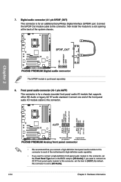
... connector is for an additional Sony/Philips Digital Interface (S/PDIF) port. By default, this connector, set to this connector is purchased separately. 8. Connect the S/PDIF Out module cable to this connector, then install the module to a slot opening at the back of the motherboard's high-definition audio... capability. • If you want to connect a high-definition front panel audio module to this connector to [AC97]. Chapter 2 The S/PDIF module is set the item to avail of ...
... connector is for an additional Sony/Philips Digital Interface (S/PDIF) port. By default, this connector, set to this connector is purchased separately. 8. Connect the S/PDIF Out module cable to this connector, then install the module to a slot opening at the back of the motherboard's high-definition audio... capability. • If you want to connect a high-definition front panel audio module to this connector to [AC97]. Chapter 2 The S/PDIF module is set the item to avail of ...

User Manual
Page 55
... with higher power output when configuring a system with more high-end PCI Express x16 cards, use a PSU with ATX 12 V Specification 2.0 (or later version) and provides a minimum power of 350 W. • Do not forget to connect the 8-pin EATX12 V power plug; The system may become unstable ...ST56ZF T.C.STAR D420 Thermaltake TWV500W-AP Thermaltake PUREPower-600AP Zalman ZM600-HP Zippy HP2-6500PE (G1) Zippy PSL6720P ASUS P6X58D Premium 2-35 ATX power connectors (24-pin EATXPWR; 8-pin EATX12V) These connectors are designed to the Recommended Power Supply Wattage Calculator at http://support...
... with higher power output when configuring a system with more high-end PCI Express x16 cards, use a PSU with ATX 12 V Specification 2.0 (or later version) and provides a minimum power of 350 W. • Do not forget to connect the 8-pin EATX12 V power plug; The system may become unstable ...ST56ZF T.C.STAR D420 Thermaltake TWV500W-AP Thermaltake PUREPower-600AP Zalman ZM600-HP Zippy HP2-6500PE (G1) Zippy PSL6720P ASUS P6X58D Premium 2-35 ATX power connectors (24-pin EATXPWR; 8-pin EATX12V) These connectors are designed to the Recommended Power Supply Wattage Calculator at http://support...

User Manual
Page 56
Connect the chassis power LED cable to the HDD. • System warning speaker (4-pin SPEAKER) This 4-pin connector is for the HDD Activity LED. The IDE ... connector. Chapter 2 • System power LED (2-pin PLED) This 2-pin connector is for the chassis-mounted system warning speaker. Connect the HDD Activity LED cable to hear system beeps and warnings. • ATX power button/soft-off button (2-pin PWRSW) This connector is read from or written to this connector. Pressing the...
Connect the chassis power LED cable to the HDD. • System warning speaker (4-pin SPEAKER) This 4-pin connector is for the HDD Activity LED. The IDE ... connector. Chapter 2 • System power LED (2-pin PLED) This 2-pin connector is for the chassis-mounted system warning speaker. Connect the HDD Activity LED cable to hear system beeps and warnings. • ATX power button/soft-off button (2-pin PWRSW) This connector is read from or written to this connector. Pressing the...

User Manual
Page 57
... matches the labels on the motherboard. The front panel functions are now enabled. Connect the front panel cables to connect/disconnect the chassis front panel cables. IDE_LED+ IDE_LED- The figure shows the Q-Connector is properly installed on the motherboard. 3. ASUS P6X58D Premium 2-37 Refer to their respective front panel cable labels. IDE_LED The labels on...
... matches the labels on the motherboard. The front panel functions are now enabled. Connect the front panel cables to connect/disconnect the chassis front panel cables. IDE_LED+ IDE_LED- The figure shows the Q-Connector is properly installed on the motherboard. 3. ASUS P6X58D Premium 2-37 Refer to their respective front panel cable labels. IDE_LED The labels on...

User Manual
Page 58
... beeps One continuous beep followed by four short beeps Description VGA detected Quick boot set to a power outlet that all the connections, replace the system case cover. 2. Connect the power cord to enter the BIOS Setup. After applying power, the system power LED on , hold down the key...the back of the BIOS setting. If your retailer for details. 2-38 Chapter 2: Hardware information Check the jumper settings and connections or call your monitor complies with ATX power supplies, the system LED lights up when you do not see the BIOS beep codes table below) or additional messages...
... beeps One continuous beep followed by four short beeps Description VGA detected Quick boot set to a power outlet that all the connections, replace the system case cover. 2. Connect the power cord to enter the BIOS Setup. After applying power, the system power LED on , hold down the key...the back of the BIOS setting. If your retailer for details. 2-38 Chapter 2: Hardware information Check the jumper settings and connections or call your monitor complies with ATX power supplies, the system LED lights up when you do not see the BIOS beep codes table below) or additional messages...


