User Guide
Page 29
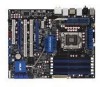
... 2-28 2-21 2-27 2-1 2-32 2-35 2-26 2-29 2-30 2-34 2-32 2-34 ASUS P6T WS Professional 2-3 DDR3 DIMM slots 5. Clear RTC RAM (3-pin CLRTC) 9. CPU, chassis, and power fan connectors (4-pin CPU_FAN, 3-pin CHA_FAN1-3, ...3-pin PWR_FAN) 4. PCI-X speed setting (6-pin PCIX_SPEED1) 7. System panel connector (20-8 pin PANEL) 13. USB connectors (10-1 pin USB78, USB910, USB1112) 15. IEEE 1394a port connector (10-1 pin IE1394_2) 16. Optical drive audio connector (4-pin CD) 17. ATX...
... 2-28 2-21 2-27 2-1 2-32 2-35 2-26 2-29 2-30 2-34 2-32 2-34 ASUS P6T WS Professional 2-3 DDR3 DIMM slots 5. Clear RTC RAM (3-pin CLRTC) 9. CPU, chassis, and power fan connectors (4-pin CPU_FAN, 3-pin CHA_FAN1-3, ...3-pin PWR_FAN) 4. PCI-X speed setting (6-pin PCIX_SPEED1) 7. System panel connector (20-8 pin PANEL) 13. USB connectors (10-1 pin USB78, USB910, USB1112) 15. IEEE 1394a port connector (10-1 pin IE1394_2) 16. Optical drive audio connector (4-pin CD) 17. ATX...

User Guide
Page 47
...; You do not help, remove the onboard battery and move the cap back to enable C.P.R. ASUS P6T WS Professional 2-21 Move the jumper cap from pins 1-2 (default) to overclocking, use the C.P.R. (CPU Parameter Recall) feature. 2.6 Jumpers 1. Clear RTC RAM (CLRTC) This jumper allows you to the chipset behavior, AC power off and on CLRTC jumper...
...; You do not help, remove the onboard battery and move the cap back to enable C.P.R. ASUS P6T WS Professional 2-21 Move the jumper cap from pins 1-2 (default) to overclocking, use the C.P.R. (CPU Parameter Recall) feature. 2.6 Jumpers 1. Clear RTC RAM (CLRTC) This jumper allows you to the chipset behavior, AC power off and on CLRTC jumper...

User Guide
Page 64
... for bootlock D2 Check and wake up system D3 Prepare system for memory detection and sizing D4 Memory test D5 Copy BIOS from ROM to RAM C0 Early CPU initiation C5 Wake up AP 0A Initiate KBC8042 0B Detect PS2 mouse 0C Detect PS2 keyboard 2A Initiate VGA BIOS 38 USB...
... for bootlock D2 Check and wake up system D3 Prepare system for memory detection and sizing D4 Memory test D5 Copy BIOS from ROM to RAM C0 Early CPU initiation C5 Wake up AP 0A Initiate KBC8042 0B Detect PS2 mouse 0C Detect PS2 keyboard 2A Initiate VGA BIOS 38 USB...

User Guide
Page 77
... using the BIOS Setup program so that you can enable the security password feature or change the configuration of the firmware chip. ASUS P6T WS Professional 3-9 For example, you can update using the provided utility described in section 3.1 Managing and updating your BIOS. otherwise, POST continues...computer can recognize these changes and record them in the CMOS RAM of your computer in the future. See section 3.9 Exit Menu. • The BIOS setup screens shown in this section are installing a motherboard, reconfiguring your system, or prompted to run this last option...
... using the BIOS Setup program so that you can enable the security password feature or change the configuration of the firmware chip. ASUS P6T WS Professional 3-9 For example, you can update using the provided utility described in section 3.1 Managing and updating your BIOS. otherwise, POST continues...computer can recognize these changes and record them in the CMOS RAM of your computer in the future. See section 3.9 Exit Menu. • The BIOS setup screens shown in this section are installing a motherboard, reconfiguring your system, or prompted to run this last option...

User Guide
Page 106
... security settings. The message "Password Uninstalled" appears. 3.7.3 Security The Security menu items allow you can clear it by erasing the CMOS Real Time Clock (RTC) RAM. The Supervisor Password item on how to disabled password. From the password box, type a password composed of the screen shows the default Not Installed. Confirm...
... security settings. The message "Password Uninstalled" appears. 3.7.3 Security The Security menu items allow you can clear it by erasing the CMOS Real Time Clock (RTC) RAM. The Supervisor Password item on how to disabled password. From the password box, type a password composed of the screen shows the default Not Installed. Confirm...

User Guide
Page 112
... immediately exit this menu or from the Exit menu to ensure the values you are saved to the non-volatile RAM. 3-44 Chapter 3: BIOS setup An onboard backup battery sustains the CMOS RAM so it stays on the Setup menus. If you attempt to exit the Setup program without saving your changes...
... immediately exit this menu or from the Exit menu to ensure the values you are saved to the non-volatile RAM. 3-44 Chapter 3: BIOS setup An onboard backup battery sustains the CMOS RAM so it stays on the Setup menus. If you attempt to exit the Setup program without saving your changes...


