P5WDG2 WS Professional English Edition User's Manual
Page 27
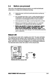
...bag that came with a standby power LED. P5WDG2-WS PRO ® SB_PWR ON Standby Power P5WDG2-WS PRO Onboard LED OFF Powered Off ASUS P5WDG2 WS Professional 2-1 The green LED lights up to the motherboard, peripherals, and/or components. Onboard LED The motherboard comes with the component. • Before you...ATX power supply is ON, in sleep mode, or in any motherboard component. The illustration below shows the location of the following precautions before you install motherboard components or change any motherboard settings. • Unplug the power cord from the wall socket ...
...bag that came with a standby power LED. P5WDG2-WS PRO ® SB_PWR ON Standby Power P5WDG2-WS PRO Onboard LED OFF Powered Off ASUS P5WDG2 WS Professional 2-1 The green LED lights up to the motherboard, peripherals, and/or components. Onboard LED The motherboard comes with the component. • Before you...ATX power supply is ON, in sleep mode, or in any motherboard component. The illustration below shows the location of the following precautions before you install motherboard components or change any motherboard settings. • Unplug the power cord from the wall socket ...

P5WDG2 WS Professional English Edition User's Manual
Page 28
Failure to do so can damage the motherboard. Place this side towards the rear of the chassis ® P5WDG2 WS PRO 2-2 Chapter 2: Hardware information Do not overtighten the screws! Doing so can cause you place it into the chassis in the image below. 2.2.2 Screw... holes Place nine (9) screws into it. Make sure to unplug the power cord before installing or removing the motherboard. The edge with ...
Failure to do so can damage the motherboard. Place this side towards the rear of the chassis ® P5WDG2 WS PRO 2-2 Chapter 2: Hardware information Do not overtighten the screws! Doing so can cause you place it into the chassis in the image below. 2.2.2 Screw... holes Place nine (9) screws into it. Make sure to unplug the power cord before installing or removing the motherboard. The edge with ...

P5WDG2 WS Professional English Edition User's Manual
Page 30
EATXPWR PRI_IDE 30.5cm (12.0in) 2.2.4 Motherboard layout 24.5cm (9.6in) PS/2KBMS T: Mouse B: Keyboard SPDIF_O1 SPDIF_O2 EATX12V LGA775 CPU_FAN PWR_FAN Super I/O FLOPPY ® P5WDG2 WS PRO DDR2 DIMM_A1 (64 bit,240-pin module) DDR2 DIMM_A2 (64 bit,240-pin module) DDR2 DIMM_B1 (64 bit,240-pin module) DDR2 DIMM_B2 (64 bit,...
EATXPWR PRI_IDE 30.5cm (12.0in) 2.2.4 Motherboard layout 24.5cm (9.6in) PS/2KBMS T: Mouse B: Keyboard SPDIF_O1 SPDIF_O2 EATX12V LGA775 CPU_FAN PWR_FAN Super I/O FLOPPY ® P5WDG2 WS PRO DDR2 DIMM_A1 (64 bit,240-pin module) DDR2 DIMM_A2 (64 bit,240-pin module) DDR2 DIMM_B1 (64 bit,240-pin module) DDR2 DIMM_B2 (64 bit,...
P5WDG2 WS Professional English Edition User's Manual
Page 34
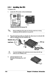
... to a 135º angle. 2-8 Chapter 2: Hardware information Lift the load lever in the direction of the socket box should face you are installing a CPU. 3. P5WDG2-WS PRO ® P5WDG2-WS PRO CPU Socket 775 Before installing the CPU, make sure that the socket box is facing towards you and the load lever is released from the... to the socket pins, do not remove the PnP cap unless you . Locate the CPU socket on your thumb (A), then move it is on the motherboard. 2.3.1 Installing the CPU To install a CPU: 1.
... to a 135º angle. 2-8 Chapter 2: Hardware information Lift the load lever in the direction of the socket box should face you are installing a CPU. 3. P5WDG2-WS PRO ® P5WDG2-WS PRO CPU Socket 775 Before installing the CPU, make sure that the socket box is facing towards you and the load lever is released from the... to the socket pins, do not remove the PnP cap unless you . Locate the CPU socket on your thumb (A), then move it is on the motherboard. 2.3.1 Installing the CPU To install a CPU: 1.
P5WDG2 WS Professional English Edition User's Manual
Page 37
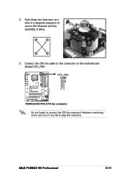
Connect the CPU fan cable to secure the heatsink and fan assembly in place. A B A B A B B A 3. ASUS P5WDG2 WS Professional 2-11 2. Push down two fasteners at a time in a diagonal sequence to the connector on the motherboard labeled CPU_FAN. Hardware monitoring errors can occur if you fail to connect the CPU fan connector! CPU_FAN P5WDG2-WS PRO CPU FAN PWM CPU FAN IN CPU FAN PWR GND ® P5WDG2-WS PRO CPU fan connector Do not forget to plug this connector.
Connect the CPU fan cable to secure the heatsink and fan assembly in place. A B A B A B B A 3. ASUS P5WDG2 WS Professional 2-11 2. Push down two fasteners at a time in a diagonal sequence to the connector on the motherboard labeled CPU_FAN. Hardware monitoring errors can occur if you fail to connect the CPU fan connector! CPU_FAN P5WDG2-WS PRO CPU FAN PWM CPU FAN IN CPU FAN PWR GND ® P5WDG2-WS PRO CPU fan connector Do not forget to plug this connector.
P5WDG2 WS Professional English Edition User's Manual
Page 40
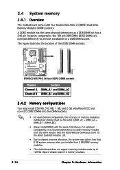
...DDR2 memory modules. • This motherboard does not support memory modules made up of 128 Mb chips or double sided x16 memory modules. 2-14 Chapter 2: Hardware information Visit the ASUS website (www.asus.com) for the latest Qualified Vendors ...P5WDG2-WS PRO ® DIMM_A1 DIMM_A2 DIMM_B1 DIMM_B2 P5WDG2-WS PRO 240-pin DDR2 DIMM sockets Channel Channel A Channel B Sockets DIMM_A1 and DIMM_A2 DIMM_B1 and DIMM_B2 2.4.2 Memory configurations You may detect less than 8 GB system memory when you obtain memory modules from the same vendor. 2.4 System memory 2.4.1 Overview The motherboard...
...DDR2 memory modules. • This motherboard does not support memory modules made up of 128 Mb chips or double sided x16 memory modules. 2-14 Chapter 2: Hardware information Visit the ASUS website (www.asus.com) for the latest Qualified Vendors ...P5WDG2-WS PRO ® DIMM_A1 DIMM_A2 DIMM_B1 DIMM_B2 P5WDG2-WS PRO 240-pin DDR2 DIMM sockets Channel Channel A Channel B Sockets DIMM_A1 and DIMM_A2 DIMM_B1 and DIMM_B2 2.4.2 Memory configurations You may detect less than 8 GB system memory when you obtain memory modules from the same vendor. 2.4 System memory 2.4.1 Overview The motherboard...

P5WDG2 WS Professional English Edition User's Manual
Page 58
Insert one of the floppy disk drive. PIN 1 P5WDG2-WS PRO Floppy disk drive connector 2 . Primary IDE connector (40-1 pin PRI_IDE) The onboard IDE connector is for the provided floppy disk drive (FDD) signal cable. This .../66 signal cable. P5WDG2-WS PRO ® PRI_IDE P5WDG2-WS PRO IDE connector NOTE: Orient the red markings (usually zigzag) on the IDE ribbon cable to PIN 1. • Pin 20 on the IDE connector is removed to prevent incorrect cable connection when using a FDD cable with a covered Pin 5. Connect the blue connector to the motherboard's IDE connector...
Insert one of the floppy disk drive. PIN 1 P5WDG2-WS PRO Floppy disk drive connector 2 . Primary IDE connector (40-1 pin PRI_IDE) The onboard IDE connector is for the provided floppy disk drive (FDD) signal cable. This .../66 signal cable. P5WDG2-WS PRO ® PRI_IDE P5WDG2-WS PRO IDE connector NOTE: Orient the red markings (usually zigzag) on the IDE ribbon cable to PIN 1. • Pin 20 on the IDE connector is removed to prevent incorrect cable connection when using a FDD cable with a covered Pin 5. Connect the blue connector to the motherboard's IDE connector...

P5WDG2 WS Professional English Edition User's Manual
Page 61
HD-Audio-compliant pin definition Legacy AC'97-compliant pin definition AAFP P5WDG2-WS PRO Front panel audio connector • We recommend that supports either HD Audio or legacy AC'97 audio standard. ... of the motherboard's High Definition Audio capability. CD (black) P5WDG2-WS PRO Internal audio connector 6 . P5WDG2-WS PRO AGND PRESENCE# SENSE1_RETUR SENSE2_RETUR ® AGND NC NC NC MIC_L MIC_R Line out_R NC Line out_L PORT1 L PORT1 R PORT2 R SENSE_SEND PORT2 L ASUS P5WDG2 WS Professional 2-35 Right Audio Channel Ground Ground Left Audio Channel P5WDG2-WS PRO ® ...
HD-Audio-compliant pin definition Legacy AC'97-compliant pin definition AAFP P5WDG2-WS PRO Front panel audio connector • We recommend that supports either HD Audio or legacy AC'97 audio standard. ... of the motherboard's High Definition Audio capability. CD (black) P5WDG2-WS PRO Internal audio connector 6 . P5WDG2-WS PRO AGND PRESENCE# SENSE1_RETUR SENSE2_RETUR ® AGND NC NC NC MIC_L MIC_R Line out_R NC Line out_L PORT1 L PORT1 R PORT2 R SENSE_SEND PORT2 L ASUS P5WDG2 WS Professional 2-35 Right Audio Channel Ground Ground Left Audio Channel P5WDG2-WS PRO ® ...

P5WDG2 WS Professional English Edition User's Manual
Page 62
... to any of these connectors, then install the module to the USB connectors. P5WDG2-WS PRO ® TPA2+ GND TPB2+ +12V TPA1+ GND TPB1+ +12V TPA2GND TPB2+12V GND IE1394_1 IE1394_2 TPA1GND TPB1+12V GND P5WDG2-WS PRO IEEE 1394 connectors Never connect a U S B p o r t m ... USB_P6USB_P6+ GND NC USB+5V USB_P7USB_P7+ GND USB+5V USB_P5USB_P5+ GND USB56 P5WDG2-WS PRO USB 2.0 connectors USB78 1 Never connect a 1 3 9 4 c a b l e to a slot opening at the back of the system chassis. Doing so will damage the motherboard! 2-36 Chapter 2: Hardware information I E E E 1 3 9 4a...
... to any of these connectors, then install the module to the USB connectors. P5WDG2-WS PRO ® TPA2+ GND TPB2+ +12V TPA1+ GND TPB1+ +12V TPA2GND TPB2+12V GND IE1394_1 IE1394_2 TPA1GND TPB1+12V GND P5WDG2-WS PRO IEEE 1394 connectors Never connect a U S B p o r t m ... USB_P6USB_P6+ GND NC USB+5V USB_P7USB_P7+ GND USB+5V USB_P5USB_P5+ GND USB56 P5WDG2-WS PRO USB 2.0 connectors USB78 1 Never connect a 1 3 9 4 c a b l e to a slot opening at the back of the system chassis. Doing so will damage the motherboard! 2-36 Chapter 2: Hardware information I E E E 1 3 9 4a...

P5WDG2 WS Professional English Edition User's Manual
Page 64
...motherboard, making sure that you install two VGA cards, we recommend that the black wire of each cable matches the ground pin of 1 A ~ 3.48 A (41.76 W max.) at +12V. PWR_FAN CPU_FAN CPU_FAN CHA_FAN1 CPU FAN PWM CPU FAN IN CPU FAN PWR GND GND CHASSIS FAN POWER SPEED P5WDG2-WS PRO... ® CHA_FAN1 CHA_FAN2 CHA_FAN2 P5WDG2-WS PRO Fan connectors GND +12V Rotation PWR_FAN Rotation +12V GND Only the CPU_FAN and CHA_FAN1 connectors support the ASUS Q-Fan 2 feature. Connect the fan cables to the fan ...
...motherboard, making sure that you install two VGA cards, we recommend that the black wire of each cable matches the ground pin of 1 A ~ 3.48 A (41.76 W max.) at +12V. PWR_FAN CPU_FAN CPU_FAN CHA_FAN1 CPU FAN PWM CPU FAN IN CPU FAN PWR GND GND CHASSIS FAN POWER SPEED P5WDG2-WS PRO... ® CHA_FAN1 CHA_FAN2 CHA_FAN2 P5WDG2-WS PRO Fan connectors GND +12V Rotation PWR_FAN Rotation +12V GND Only the CPU_FAN and CHA_FAN1 connectors support the ASUS Q-Fan 2 feature. Connect the fan cables to the fan ...

P5WDG2 WS Professional English Edition User's Manual
Page 79
... to a floppy disk or a USB flash disk, then restart the system. 3. R O M. 2. Press + during the Power-On Self Tests (POST). ASUS P5WDG2 WS Professional 4-5 You can supp ort devices such as USB flash disk, or floppy disk with FAT 32/16 format and single partition only. • Do... using EZ Flash 2: 1. Visit the ASUS website (www.asus.com) to download the latest BIOS file for the motherboard and rename the same to W D G 2 W S P . ASUSTek EZ Flash 2 BIOS ROM Utility V3.00 FLASH TYPE: Winbond W39V080A 8Mb LPC Current ROM BOARD: P5WDG2-WS Pro VER: 0204 DATE: 07/04/2006...
... to a floppy disk or a USB flash disk, then restart the system. 3. R O M. 2. Press + during the Power-On Self Tests (POST). ASUS P5WDG2 WS Professional 4-5 You can supp ort devices such as USB flash disk, or floppy disk with FAT 32/16 format and single partition only. • Do... using EZ Flash 2: 1. Visit the ASUS website (www.asus.com) to download the latest BIOS file for the motherboard and rename the same to W D G 2 W S P . ASUSTek EZ Flash 2 BIOS ROM Utility V3.00 FLASH TYPE: Winbond W39V080A 8Mb LPC Current ROM BOARD: P5WDG2-WS Pro VER: 0204 DATE: 07/04/2006...


