
Motherboard Installation Guide
Page 6
Contents Using the Virtual Cable Tester 5-9 5.4.3 Audio configurations 5-10 5.5 RAID configurations 5-16 5.5.1 Installing hard disks 5-16 5.5.2 ULI® RAID configurations 5-17 5.6 Creating a RAID driver disk 5-22 Appendix: CPU features A.1 Enhanced Intel SpeedStep® Technology (EIST A-1 A.1.1 System requirements A-1 A.1.2 Using the EIST A-1 A.2 Intel® Hyper-Threading Technology A-3 Using the Hyper-Threading Technology A-3 vi
Contents Using the Virtual Cable Tester 5-9 5.4.3 Audio configurations 5-10 5.5 RAID configurations 5-16 5.5.1 Installing hard disks 5-16 5.5.2 ULI® RAID configurations 5-17 5.6 Creating a RAID driver disk 5-22 Appendix: CPU features A.1 Enhanced Intel SpeedStep® Technology (EIST A-1 A.1.1 System requirements A-1 A.1.2 Using the EIST A-1 A.2 Intel® Hyper-Threading Technology A-3 Using the Hyper-Threading Technology A-3 vi

Motherboard Installation Guide
Page 11
P5RD1-V specifications summary CPU Chipset Front Side Bus Memory Expansion slots Integrated Graphics Storage High Definition Audio LAN Overclocking features USB LGA775 socket for Intel® Pentium® 4/Celeron processor Compatible with the Intel&#...Gigabit LAN controller Supports Marvell® Virtual Cable Tester technology Supports POST Network-diagnostic program ASUS AI Booster ASUS AI NOS (Non-delay Overclocking System) feature ASUS AI Overclocking (Intelligent CPU frequency tuner) ASUS C.P.R. (CPU Parameter Recall) CPU, Memory, and PCI Express voltage adjustable Stepless Frequency ...
P5RD1-V specifications summary CPU Chipset Front Side Bus Memory Expansion slots Integrated Graphics Storage High Definition Audio LAN Overclocking features USB LGA775 socket for Intel® Pentium® 4/Celeron processor Compatible with the Intel&#...Gigabit LAN controller Supports Marvell® Virtual Cable Tester technology Supports POST Network-diagnostic program ASUS AI Booster ASUS AI NOS (Non-delay Overclocking System) feature ASUS AI Overclocking (Intelligent CPU frequency tuner) ASUS C.P.R. (CPU Parameter Recall) CPU, Memory, and PCI Express voltage adjustable Stepless Frequency ...

Motherboard Installation Guide
Page 12
...P5RD1-V specifications summary ASUS Special features BIOS features Rear panel Internal connectors Power requirement Form Factor Support CD contents ASUS Q-Fan2 ASUS CrashFree BIOS 2 ASUS MyLogo2 4 MB Flash ROM, AMI BIOS, PnP, DMI2.0, SM BIOS 2.3, WfM2.0 1 x Parallel port 1 x VGA port 1 x LAN (RJ-45) port 4 x USB 2.0 ports 1 x PS/2 keyboard port 1 x PS/2 mouse port 8-channel audio... for 4 additional USB 2.0 ports 1 x GAME/MIDI connector 1 x Chassis intrusion connector 1 x Front panel audio connector 1 x TV-out connector 1 x S/PDIF out connector System panel connector ATX power supply (with 24-...
...P5RD1-V specifications summary ASUS Special features BIOS features Rear panel Internal connectors Power requirement Form Factor Support CD contents ASUS Q-Fan2 ASUS CrashFree BIOS 2 ASUS MyLogo2 4 MB Flash ROM, AMI BIOS, PnP, DMI2.0, SM BIOS 2.3, WfM2.0 1 x Parallel port 1 x VGA port 1 x LAN (RJ-45) port 4 x USB 2.0 ports 1 x PS/2 keyboard port 1 x PS/2 mouse port 8-channel audio... for 4 additional USB 2.0 ports 1 x GAME/MIDI connector 1 x Chassis intrusion connector 1 x Front panel audio connector 1 x TV-out connector 1 x S/PDIF out connector System panel connector ATX power supply (with 24-...

Motherboard Installation Guide
Page 16
... represents the sixth generation I/O controller hub that allows you to 150 MB/s data transfer rate. See page 2-32 for PCI Express and 8-channel high definition audio. The SATA specification allows for the motherboard. The motherboard supports the Intel® Pentium® 4 processor with Intel® 04B and 04A processors. ATI RADEON...
... represents the sixth generation I/O controller hub that allows you to 150 MB/s data transfer rate. See page 2-32 for PCI Express and 8-channel high definition audio. The SATA specification allows for the motherboard. The motherboard supports the Intel® Pentium® 4 processor with Intel® 04B and 04A processors. ATI RADEON...

Motherboard Installation Guide
Page 17
...(RPM) is monitored for four SATA connectors. See section "4.5.6 Hardware Monitor" on page 4-32. With the CODEC, 8-channel audio ports, and S/PDIF interfaces, you can connect your computer to home theater decoders to ensure stable supply of current for details. 8-...8482; interface The motherboard fully supports PCI Express, the latest I /O) to prevent overheating and damage. ASUS P5RD1-V 1-3 The ASIC monitors the voltage levels to produce crystal-clear digital audio. Onboard RAID solution The onboard ULI® M1573 allows RAID 0, RAID 1, RAID 0+1, or JBOD configuration...
...(RPM) is monitored for four SATA connectors. See section "4.5.6 Hardware Monitor" on page 4-32. With the CODEC, 8-channel audio ports, and S/PDIF interfaces, you can connect your computer to home theater decoders to ensure stable supply of current for details. 8-...8482; interface The motherboard fully supports PCI Express, the latest I /O) to prevent overheating and damage. ASUS P5RD1-V 1-3 The ASIC monitors the voltage levels to produce crystal-clear digital audio. Onboard RAID solution The onboard ULI® M1573 allows RAID 0, RAID 1, RAID 0+1, or JBOD configuration...

Motherboard Installation Guide
Page 25
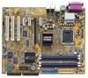
... AAFP) 16. System warning speaker (Orange 4-pin SPEAKER) - Secondary IDE connector (40-1 pin SEC_IDE) 4. USB connectors (10-1 USB56, USB78) 10. Optical audio connector (4-pin CD) 13. S/PDIF out connector (4-1 pin SPDIF) 18. Serial ATA connectors (7-pin SATA1, SATA2, SATA3, SATA4) 5. Serial port connector (10...2-pin RESET) Page 2-25 2-25 2-25 2-26 2-27 2-27 2-27 2-28 2-28 2-29 2-29 2-30 2-30 2-31 2-31 2-32 2-32 2-33 ASUS P5RD1-V 2-5 CPU fan connector (4-pin CPU_FAN) 6. ATX power connector (24-pin EATXPWR) 11. ATX 12V power connector (4-pin ATX12V) 12. Hard Disk activity (Red 2-...
... AAFP) 16. System warning speaker (Orange 4-pin SPEAKER) - Secondary IDE connector (40-1 pin SEC_IDE) 4. USB connectors (10-1 USB56, USB78) 10. Optical audio connector (4-pin CD) 13. S/PDIF out connector (4-1 pin SPDIF) 18. Serial ATA connectors (7-pin SATA1, SATA2, SATA3, SATA4) 5. Serial port connector (10...2-pin RESET) Page 2-25 2-25 2-25 2-26 2-27 2-27 2-27 2-28 2-28 2-29 2-29 2-30 2-30 2-31 2-31 2-32 2-32 2-33 ASUS P5RD1-V 2-5 CPU fan connector (4-pin CPU_FAN) 6. ATX power connector (24-pin EATXPWR) 11. ATX 12V power connector (4-pin ATX12V) 12. Hard Disk activity (Red 2-...

Motherboard Installation Guide
Page 38
... 1 PCI E x1 slot 2 PCI E x1 slot 3 PCI E x16 slot Onboard USB controller 1 Onboard USB controller 2 Onboard USB controller 3 Onboard USB 2.0 controller Onboard LAN Onboard HD audio A B C D E F G H - shared shared shared - - - shared - - - - - shared When using PCI cards on shared slots, ensure that the drivers support "Share IRQ" or that the cards do not...
... 1 PCI E x1 slot 2 PCI E x1 slot 3 PCI E x16 slot Onboard USB controller 1 Onboard USB controller 2 Onboard USB controller 3 Onboard USB 2.0 controller Onboard LAN Onboard HD audio A B C D E F G H - shared shared shared - - - shared - - - - - shared When using PCI cards on shared slots, ensure that the drivers support "Share IRQ" or that the cards do not...

Motherboard Installation Guide
Page 43
.../LINK SPEED LED LED LAN port 3 . ASUS P5RD1-V 2-23 S i d e S p e a k e r O u t p o r t ( b l a c k ) . 2.7 Connectors 2.7.1 Rear panel connectors 1 2 3 45 6 13 12 11 10 9 87 1 . L i n e I n p o r t ( l i g h t b l u e ) . P a r a l l e l p o r t . This port connects the tape, CD, DVD player, or other devices. 2 . This port connects a headphone or a speaker. Refer to the audio configuration table on a 4-channel, 6-channel, or 8-channel audio configuration. 4 . In 4-channel, 6-channel, and 8-channel...
.../LINK SPEED LED LED LAN port 3 . ASUS P5RD1-V 2-23 S i d e S p e a k e r O u t p o r t ( b l a c k ) . 2.7 Connectors 2.7.1 Rear panel connectors 1 2 3 45 6 13 12 11 10 9 87 1 . L i n e I n p o r t ( l i g h t b l u e ) . P a r a l l e l p o r t . This port connects the tape, CD, DVD player, or other devices. 2 . This port connects a headphone or a speaker. Refer to the audio configuration table on a 4-channel, 6-channel, or 8-channel audio configuration. 4 . In 4-channel, 6-channel, and 8-channel...

Motherboard Installation Guide
Page 44
U S B 2 . 0 p o r t s 3 a n d 4 . V G A p o r t . This port is for a PS/2 keyboard. 1 3 . U S B 2 . 0 p o r t s 1 a n d 2 . This 15-pin port connects to a VGA monitor. 1 2 . P S / 2 k e y b o a r d p o r t ( p u r p l e ) . P S / 2 m o u s e p o r t ( g r e e n ) . Audio 2, 4, 6, or 8-channel configuration Port Light Blue Lime Pink Gray Black Yellow Orange Headset 2-channel Line In Line Out Mic In • • • 4-channel Line ...
U S B 2 . 0 p o r t s 3 a n d 4 . V G A p o r t . This port is for a PS/2 keyboard. 1 3 . U S B 2 . 0 p o r t s 1 a n d 2 . This 15-pin port connects to a VGA monitor. 1 2 . P S / 2 k e y b o a r d p o r t ( p u r p l e ) . P S / 2 m o u s e p o r t ( g r e e n ) . Audio 2, 4, 6, or 8-channel configuration Port Light Blue Lime Pink Gray Black Yellow Orange Headset 2-channel Line In Line Out Mic In • • • 4-channel Line ...

Motherboard Installation Guide
Page 50
... a joystick or game pad for playing games, and MIDI devices for a GAME/MIDI port. Optical drive audio connector (4-pin CD) This connector is for playing or editing audio files. +5V J2B1 J2CX MIDI_OUT J2CY J2B2 MIDI_IN P5RD1-V ® P5RD1-V GAME connector GAME +5V J1B1 J1CX GND GND J1CY J1B2 +5V 2-30 Chapter 2: Hardware information...
... a joystick or game pad for playing games, and MIDI devices for a GAME/MIDI port. Optical drive audio connector (4-pin CD) This connector is for playing or editing audio files. +5V J2B1 J2CX MIDI_OUT J2CY J2B2 MIDI_IN P5RD1-V ® P5RD1-V GAME connector GAME +5V J1B1 J1CX GND GND J1CY J1B2 +5V 2-30 Chapter 2: Hardware information...

Motherboard Installation Guide
Page 51
... panel connector • Use a chassis that supports either HD Audio or legacy AC '97 audio standard. The chassis intrusion sensor or switch sends a high-level signal to use the chassis intrusion detection feature. See page 4-26. 10. ASUS P5RD1-V 2-31 By default, the pins labeled "Chassis Signal" and... "Ground" are shorted with a jumper cap. Connect one end of the chassis intrusion sensor or switch cable to use the high-definition audio features. • The default setting of...
... panel connector • Use a chassis that supports either HD Audio or legacy AC '97 audio standard. The chassis intrusion sensor or switch sends a high-level signal to use the chassis intrusion detection feature. See page 4-26. 10. ASUS P5RD1-V 2-31 By default, the pins labeled "Chassis Signal" and... "Ground" are shorted with a jumper cap. Connect one end of the chassis intrusion sensor or switch cable to use the high-definition audio features. • The default setting of...

Motherboard Installation Guide
Page 52
... information TV-out connector (6-1 pin TV_OUT) This 6-1 pin connector is purchased separately. +5V SPDIFOUT GND P5RD1-V ® SPDIF_OUT P5RD1-V Digital audio connector 13. Connect one end of the S/PDIF audio cable to this connector and the other end to the TV-out module. The S/PDIF module is for... the S/PDIF audio module to your system. Digital Audio connector (6-1 pin SPDIF_OUT) This connector is ...
... information TV-out connector (6-1 pin TV_OUT) This 6-1 pin connector is purchased separately. +5V SPDIFOUT GND P5RD1-V ® SPDIF_OUT P5RD1-V Digital audio connector 13. Connect one end of the S/PDIF audio cable to this connector and the other end to the TV-out module. The S/PDIF module is for... the S/PDIF audio module to your system. Digital Audio connector (6-1 pin SPDIF_OUT) This connector is ...

Motherboard Installation Guide
Page 86
... ROM Onboard LAN OnBoard LAN Boot ROM [Azalia Only] [Enabled] [Disabled] [Enabled] [Enabled] AC97 & Azalia LINK A [Azalia Only] Disables or sets the AC97 and Azalia audio link. Configuration options: [NTSC] [PAL] SouthBridge configuration The SouthBridge configuration submenu allows you do not have a TV out module installed. Configuration options: [Disabled] [Enabled] Onboard...
... ROM Onboard LAN OnBoard LAN Boot ROM [Azalia Only] [Enabled] [Disabled] [Enabled] [Enabled] AC97 & Azalia LINK A [Azalia Only] Disables or sets the AC97 and Azalia audio link. Configuration options: [NTSC] [PAL] SouthBridge configuration The SouthBridge configuration submenu allows you do not have a TV out module installed. Configuration options: [Disabled] [Enabled] Onboard...

Motherboard Installation Guide
Page 102
.... ULI Chipset Driver Installs the ULI® chipset drivers. USB 2.0 Driver Installs the Universal Serial Bus 2.0 (USB 2.0) driver. 5-2 Chapter 5: Software support Realtek Audio Driver Installs the Realtek® audio driver and application. ATI RADEON XPRESS 200 Chipset Driver Installs the ATI™ RADEON® XPRESS 200 chipset drivers. Install the necessary drivers...
.... ULI Chipset Driver Installs the ULI® chipset drivers. USB 2.0 Driver Installs the Universal Serial Bus 2.0 (USB 2.0) driver. 5-2 Chapter 5: Software support Realtek Audio Driver Installs the Realtek® audio driver and application. ATI RADEON XPRESS 200 Chipset Driver Installs the ATI™ RADEON® XPRESS 200 chipset drivers. Install the necessary drivers...

Motherboard Installation Guide
Page 110
...allows you will find the SoundEffect icon on the Line-In, Line-Out, and Mic jacks only. If the Realtek audio software is correctly installed, you to set your listening environment, adjust the equalizer, set the karaoke, or select pre.... The ALC861 also includes the Realtek® proprietary UAJ® (Universal Audio Jack) technology for your PC. 5.3.3 Audio configurations The Realtek® ALC861 High Definition Audio CODEC provides 8-channel audio capability to deliver the ultimate audio experience on your listening pleasure. 5-10 Chapter 5: Software support Follow the ...
...allows you will find the SoundEffect icon on the Line-In, Line-Out, and Mic jacks only. If the Realtek audio software is correctly installed, you to set your listening environment, adjust the equalizer, set the karaoke, or select pre.... The ALC861 also includes the Realtek® proprietary UAJ® (Universal Audio Jack) technology for your PC. 5.3.3 Audio configurations The Realtek® ALC861 High Definition Audio CODEC provides 8-channel audio capability to deliver the ultimate audio experience on your listening pleasure. 5-10 Chapter 5: Software support Follow the ...

Motherboard Installation Guide
Page 111
...Click the Exit (X ) button on the buttons. 4. To set the S/PDIF options: 1. The audio settings take effect immediately after you to change your S/PDIF output settings. ASUS P5RD1-V 5-11 Click the Exit (X ) button on the upper-right hand corner of the window to ...exit. To set the sound effect options: 1. From the Realtek Audio Control Panel, click the S P D I F button. 2. From the Realtek Audio Control Panel, click the S o u n d...
...Click the Exit (X ) button on the buttons. 4. To set the S/PDIF options: 1. The audio settings take effect immediately after you to change your S/PDIF output settings. ASUS P5RD1-V 5-11 Click the Exit (X ) button on the upper-right hand corner of the window to ...exit. To set the sound effect options: 1. From the Realtek Audio Control Panel, click the S P D I F button. 2. From the Realtek Audio Control Panel, click the S o u n d...

Motherboard Installation Guide
Page 112
To set your current speaker setup, then click A u t o T e s t to exit. 5-12 Chapter 5: Software support Click the Exit (X ) button on the upper-right hand corner of the window to test your settings. 3. Select from the combo list box your speaker configuration. From the Realtek Audio Control Panel, click the S p e a k e r C o n f i g u r a t i o n button. 2. Click the U A J A u t o m a t i c button to set the speaker configuration: 1. Speaker Configuration This option allows you to enable or disable the Universal Audio Jack(UAJ®) technology feature. 4.
To set your current speaker setup, then click A u t o T e s t to exit. 5-12 Chapter 5: Software support Click the Exit (X ) button on the upper-right hand corner of the window to test your settings. 3. Select from the combo list box your speaker configuration. From the Realtek Audio Control Panel, click the S p e a k e r C o n f i g u r a t i o n button. 2. Click the U A J A u t o m a t i c button to set the speaker configuration: 1. Speaker Configuration This option allows you to enable or disable the Universal Audio Jack(UAJ®) technology feature. 4.

Motherboard Installation Guide
Page 113
ASUS P5RD1-V 5-13 Make sure to change sensing options. 4. When finished, the utility prompts the Realtek® EZ-connection dialog box showing your audio connection status. To start connection sensing. From the Realtek Audio Control Panel, click the C o n n e c t o r S e n s i n g button. 2. Click the S t a r t button to start the connector sensing: 1. Click the O p t i o n button to exit all audio applications before...
ASUS P5RD1-V 5-13 Make sure to change sensing options. 4. When finished, the utility prompts the Realtek® EZ-connection dialog box showing your audio connection status. To start connection sensing. From the Realtek Audio Control Panel, click the C o n n e c t o r S e n s i n g button. 2. Click the S t a r t button to start the connector sensing: 1. Click the O p t i o n button to exit all audio applications before...

Motherboard Installation Guide
Page 114
... Demo This option shows a demo of the window to start the HRTF demo: 1. Click the option buttons to the proper audio jack and repeat connector sensing. 7. Click the P l a y button to exit audio control panel. To start or the S t o p button to exit EZ-connection dialog box. 8. Click the Exit (X ) button on the... upper-right hand corner of the Head-Related Transfer Functions (HRTF). If there are detected problems, make sure that your audio cables are connected to change the sound, moving path or EAX settings. 3. 6. Click the X button to stop. 4.
... Demo This option shows a demo of the window to start the HRTF demo: 1. Click the option buttons to the proper audio jack and repeat connector sensing. 7. Click the P l a y button to exit audio control panel. To start or the S t o p button to exit EZ-connection dialog box. 8. Click the Exit (X ) button on the... upper-right hand corner of the Head-Related Transfer Functions (HRTF). If there are detected problems, make sure that your audio cables are connected to change the sound, moving path or EAX settings. 3. 6. Click the X button to stop. 4.

Motherboard Installation Guide
Page 115
ASUS P5RD1-V 5-15 Rear panel audio ports function variation The functions of the window to change language display. 4. See the 8, 6, 4 or 2-channel speaker configuration on page 2-24. From the Realtek Audio Control Panel, click the G e n e r a l button. 2. Click the L a n g u a g e combo list box to exit. Click the ... the SoundEffect icon display on the Windows taskbar. General settings This option shows the audio settings and allows you select the 4-channel, 6-channel or 8-channel audio configuration as shown in the following table. Click the option button to change when ...
ASUS P5RD1-V 5-15 Rear panel audio ports function variation The functions of the window to change language display. 4. See the 8, 6, 4 or 2-channel speaker configuration on page 2-24. From the Realtek Audio Control Panel, click the G e n e r a l button. 2. Click the L a n g u a g e combo list box to exit. Click the ... the SoundEffect icon display on the Windows taskbar. General settings This option shows the audio settings and allows you select the 4-channel, 6-channel or 8-channel audio configuration as shown in the following table. Click the option button to change when ...

