
Motherboard Installation Guide
Page 4
...setup 4.1 Managing and updating your BIOS 4-1 4.1.1 Creating a bootable floppy disk 4-1 4.1.2 AFUDOS utility 4-2 4.1.3 ASUS CrashFree BIOS 2 utility 4-5 4.1.4 ASUS EZ Flash utility 4-7 4.1.5 ASUS Update utility 4-8 4.2 BIOS setup program 4-11 4.2.1 BIOS menu screen 4-12 4.2.2 Menu bar 4-12 4.2.3... Navigation keys 4-12 4.2.4 Menu items 4-13 4.2.5 Sub-menu items 4-13 4.2.6 Configuration fields 4-13 4.2.7 Pop-up window 4-13 4.2.8...
...setup 4.1 Managing and updating your BIOS 4-1 4.1.1 Creating a bootable floppy disk 4-1 4.1.2 AFUDOS utility 4-2 4.1.3 ASUS CrashFree BIOS 2 utility 4-5 4.1.4 ASUS EZ Flash utility 4-7 4.1.5 ASUS Update utility 4-8 4.2 BIOS setup program 4-11 4.2.1 BIOS menu screen 4-12 4.2.2 Menu bar 4-12 4.2.3... Navigation keys 4-12 4.2.4 Menu items 4-13 4.2.5 Sub-menu items 4-13 4.2.6 Configuration fields 4-13 4.2.7 Pop-up window 4-13 4.2.8...

Motherboard Installation Guide
Page 27
Press the load lever with your thumb (A) and move it is released from the load plate window to the left corner of the socket. Retention tab A Load lever PnP Cap B This side of the arrow to the socket pins, do not remove ... a 135º angle. 4. Load plate 5. 2. Lift the load lever in the direction of the cam box should fit A l i g n m e n t k e y into the CPU notch. Gold triangle mark ASUS P5RD1-V A 2-7 Lift the load plate with your thumb and forefinger to a 100º angle (A), then push the PnP cap B from the retention tab. The socket alignment...
Press the load lever with your thumb (A) and move it is released from the load plate window to the left corner of the socket. Retention tab A Load lever PnP Cap B This side of the arrow to the socket pins, do not remove ... a 135º angle. 4. Load plate 5. 2. Lift the load lever in the direction of the cam box should fit A l i g n m e n t k e y into the CPU notch. Gold triangle mark ASUS P5RD1-V A 2-7 Lift the load plate with your thumb and forefinger to a 100º angle (A), then push the PnP cap B from the retention tab. The socket alignment...

Motherboard Installation Guide
Page 46
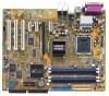
...RAID 0, RAID 1, RAID 0+1, and JBOD configuration using Serial ATA. 2-26 Chapter 2: Hardware information P5RD1-V ® SATA3 GND RSATA_TXP3 RSATA_TXN3 GND RSATA_RXP3 RSATA_RXN3 GND P5RD1-V SATA connectors SATA1 GND RSATA_TXP1 RSATA_TXN1 GND RSATA_RXP1 RSATA_RXN1 GND SATA4 GND RSATA_TXP4 RSATA_TXN4 GND RSATA_RXP4 RSATA_RXN4... for details. Refer to set or JBOD with more than two hard disk drives. • Install the Windows® 2000 Service Pack 4 or the Windows® XP Service Pack1 or later when using the ULI® RAID controller. Serial ATA connectors (7-pin ...
...RAID 0, RAID 1, RAID 0+1, and JBOD configuration using Serial ATA. 2-26 Chapter 2: Hardware information P5RD1-V ® SATA3 GND RSATA_TXP3 RSATA_TXN3 GND RSATA_RXP3 RSATA_RXN3 GND P5RD1-V SATA connectors SATA1 GND RSATA_TXP1 RSATA_TXN1 GND RSATA_RXP1 RSATA_RXN1 GND SATA4 GND RSATA_TXP4 RSATA_TXN4 GND RSATA_RXP4 RSATA_RXN4... for details. Refer to set or JBOD with more than two hard disk drives. • Install the Windows® 2000 Service Pack 4 or the Windows® XP Service Pack1 or later when using the ULI® RAID controller. Serial ATA connectors (7-pin ...

Motherboard Installation Guide
Page 58
... for more than four seconds puts the system to sleep mode or to shut down the computer. 3. The power supply should turn off after Windows® shuts down. 3.2.2 Using the dual function power switch While the system is selected, then click the O K button to soft-off ...mode, depending on the BIOS setting. The power supply should turn off after Windows® shuts down. Refer to shut down the computer. 3. Click the S t a r t button then click S h u t D o w n . . . 2. 3.2 Powering off the computer 3.2.1 Using the ...
... for more than four seconds puts the system to sleep mode or to shut down the computer. 3. The power supply should turn off after Windows® shuts down. 3.2.2 Using the dual function power switch While the system is selected, then click the O K button to soft-off ...mode, depending on the BIOS setting. The power supply should turn off after Windows® shuts down. Refer to shut down the computer. 3. Click the S t a r t button then click S h u t D o w n . . . 2. 3.2 Powering off the computer 3.2.1 Using the ...

Motherboard Installation Guide
Page 61
...(Updates the BIOS in Windows® environment.) Refer to the floppy disk drive. Windows® XP environment a. A S U S E Z F l a s h (Updates the BIOS in DOS mode using a floppy disk or the motherboard support CD.) 4. At the DOS prompt, type format A:/S then press . ASUS P5RD1-V 4-1 Insert a 1.... using a bootable floppy disk.) 2. A S U S C r a s h F r e e B I O S 2 (Updates the BIOS using the ASUS Update or AFUDOS utilities. 4.1.1 Creating a bootable floppy disk 1. Copy the original motherboard BIOS using a bootable floppy disk or the motherboard support CD when the BIOS...
...(Updates the BIOS in Windows® environment.) Refer to the floppy disk drive. Windows® XP environment a. A S U S E Z F l a s h (Updates the BIOS in DOS mode using a floppy disk or the motherboard support CD.) 4. At the DOS prompt, type format A:/S then press . ASUS P5RD1-V 4-1 Insert a 1.... using a bootable floppy disk.) 2. A S U S C r a s h F r e e B I O S 2 (Updates the BIOS using the ASUS Update or AFUDOS utilities. 4.1.1 Creating a bootable floppy disk 1. Copy the original motherboard BIOS using a bootable floppy disk or the motherboard support CD when the BIOS...

Motherboard Installation Guide
Page 62
... environment To create a set of boot disks for reference only. Insert the Windows® 2000 CD to continue. 2. Click S t a r t, then select R u n. The actual BIOS screen displays may not be exactly the same as backup when the BIOS fails ... disk into the drive. d. From the Open field, type D:\bootdisk\makeboot a: assuming that you to save the file. • The succeeding BIOS screens are for Windows® 2000: a. Copying the current BIOS To copy the current BIOS file using a bootable floppy disk with the updated BIOS file. Press , then follow screen...
... environment To create a set of boot disks for reference only. Insert the Windows® 2000 CD to continue. 2. Click S t a r t, then select R u n. The actual BIOS screen displays may not be exactly the same as backup when the BIOS fails ... disk into the drive. d. From the Open field, type D:\bootdisk\makeboot a: assuming that you to save the file. • The succeeding BIOS screens are for Windows® 2000: a. Copying the current BIOS To copy the current BIOS file using a bootable floppy disk with the updated BIOS file. Press , then follow screen...

Motherboard Installation Guide
Page 68
...motherboard BIOS in Windows® environment. 4.1.5 ASUS Update utility The ASUS Update is a utility that comes with the motherboard package. ASUS Update requires an Internet connection either through a network or an Internet Service Provider (ISP). The ASUS Update utility is ...BIOS setup Click the U t i l i t i e s tab, then click I n s t a l l A S U S U p d a t e V X . Installing ASUS Update To install ASUS Update: 1. X X. The ASUS Update utility allows you to your system. X X . This utility is copied to : • Save the current BIOS file • Download the latest BIOS...
...motherboard BIOS in Windows® environment. 4.1.5 ASUS Update utility The ASUS Update is a utility that comes with the motherboard package. ASUS Update requires an Internet connection either through a network or an Internet Service Provider (ISP). The ASUS Update utility is ...BIOS setup Click the U t i l i t i e s tab, then click I n s t a l l A S U S U p d a t e V X . Installing ASUS Update To install ASUS Update: 1. X X. The ASUS Update utility allows you to your system. X X . This utility is copied to : • Save the current BIOS file • Download the latest BIOS...

Motherboard Installation Guide
Page 69
Updating the BIOS through the Internet To update the BIOS through the Internet: 1. N e x t. Click N e x t. Select U p d a t e B I n t e r n e t option from the Windows® desktop by clicking S t a r t > P r o g r a m s > A S U S > A S U S U p d a t e > A S U S U p d a t e. Launch the ASUS Update utility from the nearest you to avoid network drop-down menu, then click traffic, or click A u t o S e l e c t. Select the ASUS FTP site t h e I O S f r o m 3. The ASUS Update main window appears. 2. ASUS P5RD1-V 4-9
Updating the BIOS through the Internet To update the BIOS through the Internet: 1. N e x t. Click N e x t. Select U p d a t e B I n t e r n e t option from the Windows® desktop by clicking S t a r t > P r o g r a m s > A S U S > A S U S U p d a t e > A S U S U p d a t e. Launch the ASUS Update utility from the nearest you to avoid network drop-down menu, then click traffic, or click A u t o S e l e c t. Select the ASUS FTP site t h e I O S f r o m 3. The ASUS Update main window appears. 2. ASUS P5RD1-V 4-9

Motherboard Installation Guide
Page 70
... clicking S t a r t > P r o g r a m s > A S U S > A S U S U p d a t e > A S U S U p d a t e. Updating the BIOS through a BIOS file To update the BIOS through the Internet. The ASUS Update main window appears. 2. From the FTP site, select the BIOS version that you wish to complete the update process. The ASUS Update utility is capable of updating itself through a BIOS file: 1. Select U p d a t e B I O S f r o m a f i l e option from the drop...
... clicking S t a r t > P r o g r a m s > A S U S > A S U S U p d a t e > A S U S U p d a t e. Updating the BIOS through a BIOS file To update the BIOS through the Internet. The ASUS Update main window appears. 2. From the FTP site, select the BIOS version that you wish to complete the update process. The ASUS Update utility is capable of updating itself through a BIOS file: 1. Select U p d a t e B I O S f r o m a f i l e option from the drop...

Motherboard Installation Guide
Page 73
...Information [11:10:19] [Thu 03/27/2003] [1.44M, 3.5 in the sections below may cause system to display a pop-up window Scroll bar ASUS P5RD1-V 4-13 To display the sub-menu, select the item and press . 4.2.6 Configuration fields These fields show the values for that do ...not fit on the screen. Advanced Chipset settings WARNING: Setting wrong values in ] [English] :[ST320413A] :[ASUS CD-S340] :[Not Detected] :[Not Detected] :[Not Detected]...
...Information [11:10:19] [Thu 03/27/2003] [1.44M, 3.5 in the sections below may cause system to display a pop-up window Scroll bar ASUS P5RD1-V 4-13 To display the sub-menu, select the item and press . 4.2.6 Configuration fields These fields show the values for that do ...not fit on the screen. Advanced Chipset settings WARNING: Setting wrong values in ] [English] :[ST320413A] :[ASUS CD-S340] :[Not Detected] :[Not Detected] :[Not Detected]...

Motherboard Installation Guide
Page 97
... to exit the Setup program without saving your changes, the program prompts you with a message asking if you want to save your changes before exiting. ASUS P5RD1-V 4-37 Configuration options: [Disabled] [Enabled] 4.7 Exit menu The Exit menu items allow you select this item to [Setup], BIOS checks for user ...backup battery sustains the CMOS RAM so it stays on even when the PC is turned off. Clear User Password Select this option, a confirmation window appears. When set to clear the user password. Exit & Save Changes Once you are finished making your changes to the BIOS items. Exit ...
... to exit the Setup program without saving your changes, the program prompts you with a message asking if you want to save your changes before exiting. ASUS P5RD1-V 4-37 Configuration options: [Disabled] [Enabled] 4.7 Exit menu The Exit menu items allow you select this item to [Setup], BIOS checks for user ...backup battery sustains the CMOS RAM so it stays on even when the PC is turned off. Clear User Password Select this option, a confirmation window appears. When set to clear the user password. Exit & Save Changes Once you are finished making your changes to the BIOS items. Exit ...

Motherboard Installation Guide
Page 98
If you made changes to fields other changes before exiting. After selecting this option or if you press , a confirmation window appears. Discard Changes This option allows you to discard the selections you made to the Setup program. Select O k to load default values. Exit & Discard Changes ...
If you made changes to fields other changes before exiting. After selecting this option or if you press , a confirmation window appears. Discard Changes This option allows you to discard the selections you made to the Setup program. Select O k to load default values. Exit & Discard Changes ...

Motherboard Installation Guide
Page 101
... CD that came with the motherboard package contains the drivers, software applications, and utilities that you can install to the optical drive. ASUS P5RD1-V 5-1 5.1 Installing an operating system This motherboard supports Windows® 2000/XP operating systems (OS). E X E to change at any time without notice. Always install the latest OS version and corresponding...
... CD that came with the motherboard package contains the drivers, software applications, and utilities that you can install to the optical drive. ASUS P5RD1-V 5-1 5.1 Installing an operating system This motherboard supports Windows® 2000/XP operating systems (OS). E X E to change at any time without notice. Always install the latest OS version and corresponding...

Motherboard Installation Guide
Page 107
... drop down menu, then click N e x t. 3. ASUS P5RD1-V 5-7 Launch the ASUS Update utility. Refer to use as your boot logo. View the online help or readme file that came with the software application for details. 2. Check the option L a u n c h M y L o g o t o r e p l a c e s y s t e m b o o t l o g o b e f o r e f l a s h i n g B I O S f r o m a f i l e from the drop down menu, then click N e x t. 5. From the left window pane, select the folder that the...
... drop down menu, then click N e x t. 3. ASUS P5RD1-V 5-7 Launch the ASUS Update utility. Refer to use as your boot logo. View the online help or readme file that came with the software application for details. 2. Check the option L a u n c h M y L o g o t o r e p l a c e s y s t e m b o o t l o g o b e f o r e f l a s h i n g B I O S f r o m a f i l e from the drop down menu, then click N e x t. 5. From the left window pane, select the folder that the...

Motherboard Installation Guide
Page 108
When the logo images appear on the right window pane, select an image to your desired size by clicking on the R a t i o box. 9. After flashing the BIOS, restart the computer to load the new boot logo. 10. When the screen returns to the ASUS Update utility, flash the original BIOS to display the new boot logo during POST. 5-8 Chapter 5: Software support 7. Adjust the boot image to enlarge by selecting a value on it. 8.
When the logo images appear on the right window pane, select an image to your desired size by clicking on the R a t i o box. 9. After flashing the BIOS, restart the computer to load the new boot logo. 10. When the screen returns to the ASUS Update utility, flash the original BIOS to display the new boot logo during POST. 5-8 Chapter 5: Software support 7. Adjust the boot image to enlarge by selecting a value on it. 8.

Motherboard Installation Guide
Page 109
...can be incorporated in the BIOS. Click the R u n button to perform a cable test. • The VCT only runs on systems with Windows® XP or Windows® 2000 operating systems. • The R u n button on the LAN cable(s) connected to the LAN port(s). • If you want ...; (VCT) is detected on the Virtual Cable Tester™ main window is disabled if no problem is a cable diagnostic utility that reports LAN cable faults and shorts using the Time Domain Reflectometry (TDR) technology. ASUS P5RD1-V 5-9 The VCT feature reduces networking and support costs through a highly...
...can be incorporated in the BIOS. Click the R u n button to perform a cable test. • The VCT only runs on systems with Windows® XP or Windows® 2000 operating systems. • The R u n button on the LAN cable(s) connected to the LAN port(s). • If you want ...; (VCT) is detected on the Virtual Cable Tester™ main window is disabled if no problem is a cable diagnostic utility that reports LAN cable faults and shorts using the Time Domain Reflectometry (TDR) technology. ASUS P5RD1-V 5-9 The VCT feature reduces networking and support costs through a highly...

Motherboard Installation Guide
Page 111
From the Realtek Audio Control Panel, click the S o u n d E f f e c t button. 2. ASUS P5RD1-V 5-11 The audio settings take effect immediately after you to change the acoustic environment, adjust the equalizer, or set the karaoke to change your desired ..., click the S P D I F button. 2. Click the shortcut buttons to change your S/PDIF output settings. Click the Exit (X ) button on the upper-right hand corner of the window to exit. S/PDIF option The Sony/Philips Digital Interface (S/PDIF) options allows you click on the upper-right hand corner of the...
From the Realtek Audio Control Panel, click the S o u n d E f f e c t button. 2. ASUS P5RD1-V 5-11 The audio settings take effect immediately after you to change the acoustic environment, adjust the equalizer, or set the karaoke to change your desired ..., click the S P D I F button. 2. Click the shortcut buttons to change your S/PDIF output settings. Click the Exit (X ) button on the upper-right hand corner of the window to exit. S/PDIF option The Sony/Philips Digital Interface (S/PDIF) options allows you click on the upper-right hand corner of the...

Motherboard Installation Guide
Page 112
Select from the combo list box your current speaker setup, then click A u t o T e s t to test your speaker configuration. Click the Exit (X ) button on the upper-right hand corner of the window to enable or disable the Universal Audio Jack(UAJ®) technology feature. 4. To set your settings. 3. Click the U A J A u t o m a t i c button to exit. 5-12 Chapter 5: Software support From the Realtek Audio Control Panel, click the S p e a k e r C o n f i g u r a t i o n button. 2. Speaker Configuration This option allows you to set the speaker configuration: 1.
Select from the combo list box your current speaker setup, then click A u t o T e s t to test your speaker configuration. Click the Exit (X ) button on the upper-right hand corner of the window to enable or disable the Universal Audio Jack(UAJ®) technology feature. 4. To set your settings. 3. Click the U A J A u t o m a t i c button to exit. 5-12 Chapter 5: Software support From the Realtek Audio Control Panel, click the S p e a k e r C o n f i g u r a t i o n button. 2. Speaker Configuration This option allows you to set the speaker configuration: 1.

Motherboard Installation Guide
Page 114
... change the sound, moving path or EAX settings. 3. HRTF Demo This option shows a demo of the window to exit. 5-14 Chapter 5: Software support 6. Click the Exit (X ) button on the upper-right hand corner of the window to exit audio control panel. From the Realtek Audio Control Panel, click the H R T F D e m o button. 2. If there...
... change the sound, moving path or EAX settings. 3. HRTF Demo This option shows a demo of the window to exit. 5-14 Chapter 5: Software support 6. Click the Exit (X ) button on the upper-right hand corner of the window to exit audio control panel. From the Realtek Audio Control Panel, click the H R T F D e m o button. 2. If there...

Motherboard Installation Guide
Page 115
... rear panel change when you to enable or disable the icon display on the Windows taskbar. 3. ASUS P5RD1-V 5-15 See the 8, 6, 4 or 2-channel speaker configuration on the Windows taskbar. Click the option button to change language display. 4. Rear panel audio ...ports function variation The functions of the window to change the language setting or toggle the SoundEffect icon display on page 2-24. Click ...
... rear panel change when you to enable or disable the icon display on the Windows taskbar. 3. ASUS P5RD1-V 5-15 See the 8, 6, 4 or 2-channel speaker configuration on the Windows taskbar. Click the option button to change language display. 4. Rear panel audio ...ports function variation The functions of the window to change the language setting or toggle the SoundEffect icon display on page 2-24. Click ...


