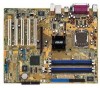
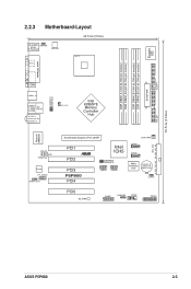
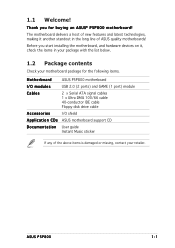
Motherboard Installation Guide
Page 23
... CPU_FAN Intel 82865PE Memory Controller Hub Marvell 88E8001 AUX CD AD1985 FP_AUDIO SPDIF_OUT Accelerated Graphics Port (AGP) PCI1 PCI2 Intel ® ICH5 USBPW56 USBPW78 PCI3 P5P800 PCI4 USB56 USB78 SEC_IDE CHA_FAN1 SATA2 SATA1 4Mbit Firmware Hub CR2032 3V Lithium Cell CMOS Power CLRTC PCI5 SB_PWR GAME CHASSIS COM2 PANEL PRI_IDE...
Motherboard Installation Guide
Page 35
Einseitig DS - ASUS P5P800 2-15 Doppelseitig Besuchen Sie die ASUS-Website für die aktuelle Liste qualifizierter Anbieter für DDR-400-Module. DDR 400 Liste qualifizierter Anbieter Größe Anbieter Modell ...
P5P800 User's manual English Edition E1906
Page 15
... the items in the long line of the above items is damaged or missing, contact your motherboard package for buying an ASUS® P5P800 motherboard! Before you for the following items. Motherboard ASUS P5P800 motherboard I/O modules USB 2.0 (2 ports) and GAME (1 port) module Cables 2 x Serial ATA signal cables 1 x Ultra DMA 100/66 cable 40-conductor...
P5P800 User's manual English Edition E1906
Page 17
...Blaster Upgrade The motherboard supports the Creative® Sound Blaster-enhanced audio upgrade that provides state-of current for critical components. 1.3.2 ASUS Proactive feature AI NET 2 AI NET 2 is a BIOS-based diagnostic tool that auto-detects the CPU loading and dynamically ... per minute (RPM) is backward compatible with digital connectivity to the LAN (RJ-45) port(s). See page 2-21 and 2-29 for details. ASUS P5P800 1-3 S/PDIF digital sound ready The motherboard supports the S/PDIF Out function through the S/PDIF interfaces on USB 2.0. USB 2.0 is monitored for timely...
P5P800 User's manual English Edition E1906
Page 20
Chapter summary 2.1 Before you proceed 2-1 2.2 Motherboard overview 2-2 2.3 Central Processing Unit (CPU 2-6 2.4 System memory 2-11 2.5 Expansion slots 2-15 2.6 Jumpers 2-20 2.7 Connectors 2-23 ASUS P5P800
P5P800 User's manual English Edition E1906
Page 21
... indicate that the system is a reminder that the ATX power supply is switched off mode. 2.1 Before you proceed Take note of the onboard LED. ® P5P800 P5P800 Onboard LED SB_PWR ON Standby Power OFF Powered Off ASUS P5P800 2-1
P5P800 User's manual English Edition E1906
Page 23
... 82865PE Memory Controller Hub Marvell 88E8001 AUX CD AD1985 FP_AUDIO SPDIF_OUT Accelerated Graphics Port (AGP) CHA_FAN1 SEC_IDE PCI1 ® SATA2 Intel ICH5 SATA1 PCI2 PCI3 P5P800 PCI4 USBPW56 USBPW78 USB56 USB78 4Mbit Firmware Hub CR2032 3V Lithium Cell CMOS Power CLRTC PCI5 SB_PWR GAME CHASSIS COM2 PANEL PRI_IDE...
P5P800 User's manual English Edition E1906
Page 25
... 4-pin SPEAKER) - Reset switch (Blue 2-pin RESET) Page 2-25 2-25 2-25 2-26 2-28 2-28 2-28 2-29 2-29 2-30 2-30 2-31 2-31 2-31 2-32 2-32 2-33 ASUS P5P800 2-5 Primary IDE connector (40-1 pin PRI_IDE) 3. Digital audio connector (4-1 pin SPDIF_OUT) 8. ATX 12V power connector (4-pin ATX12V) 12. Auxilliary audio connector (4-pin AUX) 14. System...
P5P800 User's manual English Edition E1906
Page 27
.... 4. To prevent damage to the left (B) until it to the socket pins, do not remove the PnP cap unless you . Load plate 5. Gold triangle mark ASUS P5P800 A 2-7 Lift the load plate with your thumb and forefinger to remove (B). Position the CPU over the socket, making sure that the gold triangle is released...
P5P800 User's manual English Edition E1906
Page 29
... Motherboard hole Make sure each fastener is properly applied to install. Place the heatsink on the motherboard. If you install the heatsink and fan assembly. ASUS P5P800 2-9 2.3.2 Installling the CPU heatsink and fan The Intel® Pentium® 4 LGA775 processor requires a specially designed heatsink and fan assembly to ensure optimum thermal condition...
P5P800 User's manual English Edition E1906
Page 31
B A B B A ASUS P5P800 2-11 Disconnect the CPU fan cable from the A A motherboard. Rotate each fastener counterclockwise. 3. 2.3.3 Uninstalling the CPU heatsink and fan To uninstall the CPU heatsink and fan: 1. Pull up two fasteners at a time in a diagonal sequence to disengage the heatsink B and fan assembly from the connector on the motherboard labeled CPU_FAN1. 2.
P5P800 User's manual English Edition E1906
Page 33
... chips are not supported due to the M e m o r y f r e q u e n c y / C P U F S B s y n c h r o n i z a t i o n table on page 2-14. 2. The following figure illustrates the location of the sockets: DIMM_A1 DIMM_A2 DIMM_B1 DIMM_B2 ® P5P800 P5P800 184-Pin DDR DIMM Sockets • Use the blue DIMM slots first. • Make sure to both the motherboard and the components. 2.4.2 Memory configurations You... The motherboard comes with four Double Data Rate (DDR) Dual Inline Memory Modules (DIMM) sockets. See the DDR400 Qualified Vendor List (QVL) on page 2-14. 3. ASUS P5P800 2-13
P5P800 User's manual English Edition E1906
Page 35
Single Sided D S - Double Sided Visit the ASUS website (www.asus.com) for the latest DDR 400 Qualified Vendors List. ASUS P5P800 2-15 DDR 400 Qualified Vendors List Size Vendor Model 256MB 512MB 256MB 512MB 256MB 512MB 256MB 512MB 256MB 256MB 512MB 1024MB 512MB 256MB 512MB 256MB ...
P5P800 User's manual English Edition E1906
Page 37
... cover. 2.5.2 Configuring an expansion card After installing the expansion card, configure the it and make the necessary hardware settings for later use . Refer to use . 4. ASUS P5P800 2-17 Align the card connector with the screw you may cause you intend to the tables on the system and change the necessary BIOS settings...
P5P800 User's manual English Edition E1906
Page 39
... Graphics Port (AGP) slot supports AGP8X/4X cards. Note the notches on the card golden fingers to ensure that you ask for 1.5v P5P800 Accelerated Graphics Port (AGP) ASUS P5P800 2-19 The figure shows a LAN card installed on your motherboard. Install only 1.5 V or 0.8 V AGP cards on this motherboard! 3.3V AGP cards are not...
P5P800 User's manual English Edition E1906
Page 41
ASUS P5P800 2-21 2 . The USBPWR56 and USBPWR78 jumper is for the internal USB connectors that can provide 500mA on the +5VSB lead for the rear USB ports. ... port; USB device wake-up (3-pin USBPW12, USBPW34, USBPW56, USBPW78) Set these jumpers to +5V to additional USB ports. ® P5P800 USBPW12 USBPW34 3 2 2 1 +5V (Default) +5VSB USBPW56 USBPW78 12 23 P5P800 USB device wake up +5V (Default) +5VSB • The USB device wake-up feature requires a power supply that you can connect...
P5P800 User's manual English Edition E1906
Page 43
... table below for a PS/2 mouse. 2 . L i n e O u t p o r t ( l i m e ) . This port connects the tape, CD, DVD player, or other devices. 3 . Refer to a Local Area Network (LAN) through a network hub. ASUS P5P800 2-23 2.7 Connectors 2.7.1 Rear panel connectors 1 2 3 4 5 6 11 10 9 8 7 1 . This 25-pin port connects a parallel printer, a scanner, or other audio sources. 5 . L i n e I n p o r t ( l i g h t b l u e ) . L A N R J - 4 5 p o r t . In 4-channel, and 6-channel configuration, the...
P5P800 User's manual English Edition E1906
Page 45
...hard disk drive). This prevents incorrect insertion when you must configure the second drive as a slave device by setting its jumper accordingly. PIN 1 P5P800 Floppy disk drive connector 2 . The Ultra DMA 100/66 signal cable has three connectors: a blue connector for the primary IDE connector on...documentation for the jumper settings. • The Pin 20 on the IDE connector is for Ultra DMA 100/66 IDE devices. ® P5P800 P5P800 IDE connectors ASUS P5P800 PRI_IDE SEC_IDE PIN 1 NOTE: Orient the red markings (usually zigzag) on the motherboard, a black connector for an Ultra DMA 100/...
P5P800 User's manual English Edition E1906
Page 47
... Refer to the following are the Parallel ATA and Serial ATA device configuration supported by the Intel® ICH5 specifications. P-ATA+S-ATA P-ATA Ports Only ASUS P5P800 2-27 ICH5 supports a maximum of four (4) devices using these OS. Windows® 98/ME Configuration A Configuration B Configuration C Legend: • Supported - Primary P-ATA+S-ATA Sec. See...
P5P800 User's manual English Edition E1906
Page 48
... to this connector, then install the module to a slot opening at the back of the system chassis. COM2 ® P5P800 PIN 1 P5P800 Serial port connector The Serial port 2 module is for USB 2.0 ports. ASUS P5P800 2-29 USB connectors (10-1 pin USB56, USB78) These connectors are for a serial (COM) port. Connect the USB/GAME module...