
User Manual
Page 1
P5P41T LE Motherboard
P5P41T LE Motherboard
User Manual
Page 3
Contents Notices...vi Safety information vii About this guide viii P5P41T LE specifications summary ix Chapter 1: Product introduction 1.1 Welcome 1-1 1.2 Package contents 1-1 1.3 Special features 1-1 1.3.1 Product highlights 1-1 1.3.2 Innovative ASUS features 1-2 1.4 Before you proceed 1-4 1.5 Motherboard overview 1-5 1.5.1 Placement direction 1-5 1.5.2 Screw holes 1-5 1.5.3 Motherboard layout 1-6 1.5.4 Layout contents 1-6 1.6 Central Processing Unit (CPU 1-7 1.6.1 Installing the CPU 1-7 1.6.2 Installing the CPU heatsink and fan 1-10 1.6.3 Uninstalling...
Contents Notices...vi Safety information vii About this guide viii P5P41T LE specifications summary ix Chapter 1: Product introduction 1.1 Welcome 1-1 1.2 Package contents 1-1 1.3 Special features 1-1 1.3.1 Product highlights 1-1 1.3.2 Innovative ASUS features 1-2 1.4 Before you proceed 1-4 1.5 Motherboard overview 1-5 1.5.1 Placement direction 1-5 1.5.2 Screw holes 1-5 1.5.3 Motherboard layout 1-6 1.5.4 Layout contents 1-6 1.6 Central Processing Unit (CPU 1-7 1.6.1 Installing the CPU 1-7 1.6.2 Installing the CPU heatsink and fan 1-10 1.6.3 Uninstalling...
User Manual
Page 6
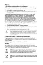
... FCC Rules. REACH Complying with the REACH (Registration, Evaluation, Authorisation, and Restriction of parts and recycling. DO NOT throw the motherboard in municipal waste. This product has been designed to radio or television reception, which the receiver is no guarantee that the battery ...undesired operation. This symbol of the crossed out wheeled bin indicates that interference will not occur in our products at ASUS REACH website at http://green.asus.com/english/REACH.htm. This class B digital apparatus complies with the limits for compliance could void the user's authority...
... FCC Rules. REACH Complying with the REACH (Registration, Evaluation, Authorisation, and Restriction of parts and recycling. DO NOT throw the motherboard in municipal waste. This product has been designed to radio or television reception, which the receiver is no guarantee that the battery ...undesired operation. This symbol of the crossed out wheeled bin indicates that interference will not occur in our products at ASUS REACH website at http://green.asus.com/english/REACH.htm. This class B digital apparatus complies with the limits for compliance could void the user's authority...

User Manual
Page 7
...not sure about the voltage of the electrical outlet you detect any area where it by yourself. Operation safety • Before installing the motherboard and adding devices on a stable surface. • If you add a device. • Before connecting or removing signal cables from ... technical problems with your dealer immediately. • To avoid short circuits, keep paper clips, screws, and staples away from the motherboard, ensure that all power cables are unplugged. • Seek professional assistance before using an adapter or extension cord. INVISIBLE LASER RADIATION...
...not sure about the voltage of the electrical outlet you detect any area where it by yourself. Operation safety • Before installing the motherboard and adding devices on a stable surface. • If you add a device. • Before connecting or removing signal cables from ... technical problems with your dealer immediately. • To avoid short circuits, keep paper clips, screws, and staples away from the motherboard, ensure that all power cables are unplugged. • Seek professional assistance before using an adapter or extension cord. INVISIBLE LASER RADIATION...
User Manual
Page 8
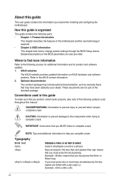
...such as warranty flyers, that you perform certain tasks properly, take note of the motherboard and the new technology it �e�m�t�o�s�e�le�c�t. Example: means that you must press the enclosed key. Conventions used throughout... describes the features of the following sources for additional information and for product and software updates. 1. ASUS websites The ASUS website provides updated information on ASUS hardware and software products. DANGER/WARNING: Information to prevent injury to yourself when trying to the...
...such as warranty flyers, that you perform certain tasks properly, take note of the motherboard and the new technology it �e�m�t�o�s�e�le�c�t. Example: means that you must press the enclosed key. Conventions used throughout... describes the features of the following sources for additional information and for product and software updates. 1. ASUS websites The ASUS website provides updated information on ASUS hardware and software products. DANGER/WARNING: Information to prevent injury to yourself when trying to the...

User Manual
Page 11
...™ 2 Duo processors, which are excellent for multitasking, multimedia, and enthusiastic gamers with the list below. 1.2 Package contents Check your motherboard package for buying an ASUS® P5P41T LE motherboard! ASUS P5P41T LE 1-1 Thank you start installing the motherboard, and hardware devices on it another standout in your package with 1333/ 1066/ 800 MHz FSB. Before you for the...
...™ 2 Duo processors, which are excellent for multitasking, multimedia, and enthusiastic gamers with the list below. 1.2 Package contents Check your motherboard package for buying an ASUS® P5P41T LE motherboard! ASUS P5P41T LE 1-1 Thank you start installing the motherboard, and hardware devices on it another standout in your package with 1333/ 1066/ 800 MHz FSB. Before you for the...

User Manual
Page 12
... is enhanced with an ACPI management function to provide efficient power management for advanced operating systems. 1.3.2 1-2 Innovative ASUS features ASUS EPU ASUS EPU (Energy Processing Unit) provides total system power management by detecting the current PC loading and intelligently moderating power... Serial ATA 3Gb/s technology This motherboard supports hard drives based on the Serial ATA (SATA) 3Gb/s storage specifications, delivering enhanced scalability and doubling the bus bandwidth for 3D graphics and other memory-demanding applications. ASUS Express Gate Express Gate is designed...
... is enhanced with an ACPI management function to provide efficient power management for advanced operating systems. 1.3.2 1-2 Innovative ASUS features ASUS EPU ASUS EPU (Energy Processing Unit) provides total system power management by detecting the current PC loading and intelligently moderating power... Serial ATA 3Gb/s technology This motherboard supports hard drives based on the Serial ATA (SATA) 3Gb/s storage specifications, delivering enhanced scalability and doubling the bus bandwidth for 3D graphics and other memory-demanding applications. ASUS Express Gate Express Gate is designed...

User Manual
Page 13
... BIOS 3 is subject to restore a corrupted BIOS file using an OS-based utility. Green ASUS This motherboard and its packaging comply with the OpenGL standard. It supports file downloading to USB devices only. • The actrual boot time is ...BIOS automatically restores the CPU parameters to open the system chassis and clear the RTC data. ASUS P5P41T LE 1-3 C.P.R. (CPU Parameter Recall) The BIOS C.P.R. eliminates the need to their default settings. Refer to http://support.asus.com for a more colorful and vivid image on the use of creating environment-friendly and ...
... BIOS 3 is subject to restore a corrupted BIOS file using an OS-based utility. Green ASUS This motherboard and its packaging comply with the OpenGL standard. It supports file downloading to USB devices only. • The actrual boot time is ...BIOS automatically restores the CPU parameters to open the system chassis and clear the RTC data. ASUS P5P41T LE 1-3 C.P.R. (CPU Parameter Recall) The BIOS C.P.R. eliminates the need to their default settings. Refer to http://support.asus.com for a more colorful and vivid image on the use of creating environment-friendly and ...
User Manual
Page 14
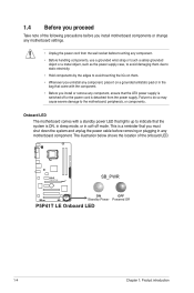
... the system is detached from the power supply. The illustration below shows the location of the following precautions before you install motherboard components or change any motherboard settings. • Unplug the power cord from the wall socket before removing or plugging in any component, ensure that the... on them. • Whenever you uninstall any component, place it on a grounded antistatic pad or in soft-off mode. P5P41T LE SB_PWR ON OFF Standby Power Powered Off P5P41T LE Onboard LED 1-4 Chapter 1: Product introduction 1.4 Before you proceed Take note of the onboard LED.
... the system is detached from the power supply. The illustration below shows the location of the following precautions before you install motherboard components or change any motherboard settings. • Unplug the power cord from the wall socket before removing or plugging in any component, ensure that the... on them. • Whenever you uninstall any component, place it on a grounded antistatic pad or in soft-off mode. P5P41T LE SB_PWR ON OFF Standby Power Powered Off P5P41T LE Onboard LED 1-4 Chapter 1: Product introduction 1.4 Before you proceed Take note of the onboard LED.
User Manual
Page 15
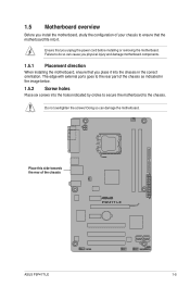
...! Failure to do so can damage the motherboard. Doing so can cause you physical injury and damage motherboard components. 1.5.1 Placement direction When installing the motherboard, ensure that you place it into the ...motherboard fits into the holes indicated by circles to secure the motherboard to ensure that you unplug the power cord before installing or removing the motherboard. 1.5 Motherboard overview Before you install the motherboard, study the configuration of your chassis to the chassis. The edge with external ports goes to the rear part of the chassis P5P41T LE ASUS P5P41T LE...
...! Failure to do so can damage the motherboard. Doing so can cause you physical injury and damage motherboard components. 1.5.1 Placement direction When installing the motherboard, ensure that you place it into the ...motherboard fits into the holes indicated by circles to secure the motherboard to ensure that you unplug the power cord before installing or removing the motherboard. 1.5 Motherboard overview Before you install the motherboard, study the configuration of your chassis to the chassis. The edge with external ports goes to the rear part of the chassis P5P41T LE ASUS P5P41T LE...
User Manual
Page 16
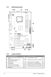
...-pin EATXPWR, 4-pin 1-21 8. 1.5.3 Motherboard layout KBMS 12 3 18.3cm(7.2in) 24 CPU_FAN ATX12V COM1 LPT DDR3 DIMM_A1 (64bit, 240-pin module) DDR3 DIMM_B1 (64bit, 240-pin module) USB34 LGA775 PRI_IDE 5 30.5cm(12.0in) LAN1_USB12 CHA_FAN Intel® G41 AUDIO ICS 9LRS954 1 EATXPWR ATHEROS AR8121 PCIEX1_1 P5P41T LE PCIEX16_1 Super I/O PCIEX1_2 Lithium...
...-pin EATXPWR, 4-pin 1-21 8. 1.5.3 Motherboard layout KBMS 12 3 18.3cm(7.2in) 24 CPU_FAN ATX12V COM1 LPT DDR3 DIMM_A1 (64bit, 240-pin module) DDR3 DIMM_B1 (64bit, 240-pin module) USB34 LGA775 PRI_IDE 5 30.5cm(12.0in) LAN1_USB12 CHA_FAN Intel® G41 AUDIO ICS 9LRS954 1 EATXPWR ATHEROS AR8121 PCIEX1_1 P5P41T LE PCIEX16_1 Super I/O PCIEX1_2 Lithium...
User Manual
Page 17
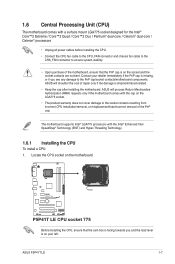
... not cover damage to the PnP cap/socket contacts/motherboard components. ASUS will process Return Merchandise Authorization (RMA) requests only if the motherboard comes with the cap on the socket and the socket contacts are not bent. Contact your left. ASUS P5P41T LE 1-7 1.6 Central Processing Unit (CPU) The motherboard comes with the Intel® Enhanced Intel SpeedStep...
... not cover damage to the PnP cap/socket contacts/motherboard components. ASUS will process Return Merchandise Authorization (RMA) requests only if the motherboard comes with the cap on the socket and the socket contacts are not bent. Contact your left. ASUS P5P41T LE 1-7 1.6 Central Processing Unit (CPU) The motherboard comes with the Intel® Enhanced Intel SpeedStep...
User Manual
Page 20
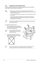
... the same. A B A B B A 1 1 B A The type of the installed CPU, ensuring that the four fasteners match the holes on the motherboard. Ensure that you have properly applied Thermal Interface Material to the CPU heatsink or CPU before you install the CPU fan and heatsink assembly. To... and requires no tool to install. • If you purchased a separate CPU heatsink and fan assembly, ensure that you have installed the motherboard to the chassis before you install the heatsink and fan assembly. 1.6.2 Installing the CPU heatsink and fan The Intel® LGA775 processor requires...
... the same. A B A B B A 1 1 B A The type of the installed CPU, ensuring that the four fasteners match the holes on the motherboard. Ensure that you have properly applied Thermal Interface Material to the CPU heatsink or CPU before you install the CPU fan and heatsink assembly. To... and requires no tool to install. • If you purchased a separate CPU heatsink and fan assembly, ensure that you have installed the motherboard to the chassis before you install the heatsink and fan assembly. 1.6.2 Installing the CPU heatsink and fan The Intel® LGA775 processor requires...

User Manual
Page 21
.... 1.6.3 Uninstalling the CPU heatsink and fan To uninstall the CPU heatsink and fan: 1. A B A B B A B A ASUS P5P41T LE 1-11 CPU_FAN CPU FAN PWM CPU FAN IN CPU FAN PWR GND P5P41T LE P5P41T LE CPU fan connector Do not forget to the connector on the motherboard. 2. Connect the CPU fan cable to connect the CPU fan connector! Rotate each fastener...
.... 1.6.3 Uninstalling the CPU heatsink and fan To uninstall the CPU heatsink and fan: 1. A B A B B A B A ASUS P5P41T LE 1-11 CPU_FAN CPU FAN PWM CPU FAN IN CPU FAN PWR GND P5P41T LE P5P41T LE CPU fan connector Do not forget to the connector on the motherboard. 2. Connect the CPU fan cable to connect the CPU fan connector! Rotate each fastener...
User Manual
Page 22
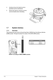
The figure illustrates the location of the DDR3 DIMM sockets: DIMM_A1 DIMM_B1 P5P41T LE Channel Channel A Channel B Sockets DIMM_A1 DIMM_B1 P5P41T LE 240-pin DDR3 DIMM sockets 1-12 Chapter 1: Product introduction Rotate each fastener clockwise to ensure correct orientation when reinstalling. 1.7 System memory 1.7.1 Overview The motherboard comes with two Double Data Rate 3 (DDR3) Dual Inline Memory Modules (DIMM) sockets. 4. Carefully remove the heatsink and fan assembly from the motherboard. 5.
The figure illustrates the location of the DDR3 DIMM sockets: DIMM_A1 DIMM_B1 P5P41T LE Channel Channel A Channel B Sockets DIMM_A1 DIMM_B1 P5P41T LE 240-pin DDR3 DIMM sockets 1-12 Chapter 1: Product introduction Rotate each fastener clockwise to ensure correct orientation when reinstalling. 1.7 System memory 1.7.1 Overview The motherboard comes with two Double Data Rate 3 (DDR3) Dual Inline Memory Modules (DIMM) sockets. 4. Carefully remove the heatsink and fan assembly from the motherboard. 5.

User Manual
Page 23
... page) Timing DIMM (BIOS) 8-8-8-24 8-8-8-24 9 9 9-9-9-24 9 9 6-6-6-20 9 9 6-6-6-20 6-6-6-20 7-7-7-24 9 Voltage 1.65-1.85V 1.65-1.85V 1.60V 1.5V 1.8V 1.8V 1.8V 1.65V DIMM Support A* B ASUS P5P41T LE 1-13 P5P41T LE Motherboard Qualified Vendors Lists (QVL) DDR3-1333 MHz capability Vendor Part No. Size SS/ DS Brand Chip NO. Under the default state, some memory modules for...
... page) Timing DIMM (BIOS) 8-8-8-24 8-8-8-24 9 9 9-9-9-24 9 9 6-6-6-20 9 9 6-6-6-20 6-6-6-20 7-7-7-24 9 Voltage 1.65-1.85V 1.65-1.85V 1.60V 1.5V 1.8V 1.8V 1.8V 1.65V DIMM Support A* B ASUS P5P41T LE 1-13 P5P41T LE Motherboard Qualified Vendors Lists (QVL) DDR3-1333 MHz capability Vendor Part No. Size SS/ DS Brand Chip NO. Under the default state, some memory modules for...
User Manual
Page 26
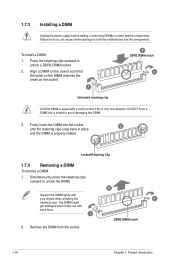
... DIMM lightly with extra force. 1 2. Firmly insert the DIMM into a socket to unlock a DDR3 DIMM socket. 2. Simultaneously press the retaining clips outward to both the motherboard and the components. The DIMM might get damaged when it fits in place 3 and the DIMM is keyed with a notch so that the notch on...
... DIMM lightly with extra force. 1 2. Firmly insert the DIMM into a socket to unlock a DDR3 DIMM socket. 2. Simultaneously press the retaining clips outward to both the motherboard and the components. The DIMM might get damaged when it fits in place 3 and the DIMM is keyed with a notch so that the notch on...
User Manual
Page 27
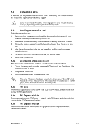
...card, read the documentation that came with the PCI Express specifications. Align the card connector with the screw you physical injury and damage motherboard components. 1.8.1 Installing an expansion card To install an expansion card: 1. Secure the card to the chassis with the slot and ... an IRQ to the card. 3. When using PCI cards on the slot. 5. Turn on BIOS setup. 2. ASUS P5P41T LE 1-17 Remove the system unit cover (if your motherboard is completely seated on shared slots, ensure that the drivers support "Share IRQ" or that you may cause you removed...
...card, read the documentation that came with the PCI Express specifications. Align the card connector with the screw you physical injury and damage motherboard components. 1.8.1 Installing an expansion card To install an expansion card: 1. Secure the card to the chassis with the slot and ... an IRQ to the card. 3. When using PCI cards on the slot. 5. Turn on BIOS setup. 2. ASUS P5P41T LE 1-17 Remove the system unit cover (if your motherboard is completely seated on shared slots, ensure that the drivers support "Share IRQ" or that you may cause you removed...

User Manual
Page 30
...motherboard components. 1.10.2 Internal connectors 1. These are not jumpers! Digital audio connector (4-1 pin SPDIF_OUT) This connector is purchased separately. 1-20 Chapter 1: Product introduction CPU_FAN CPU FAN PWM CPU FAN IN CPU FAN PWR GND P5P41T LE CHA_FAN GND +12V Rotation P5P41T LE fan connectors Only the 4-pin CPU fan connector supports the ASUS... caps on the motherboard, ensuring that the black wire of each cable matches the ground pin of 1A~2.22A (26.64W max.) at the back of the system chassis. +5V SPDIFOUT GND P5P41T LE SPDIF_OUT P5P41T LE Digital audio connector ...
...motherboard components. 1.10.2 Internal connectors 1. These are not jumpers! Digital audio connector (4-1 pin SPDIF_OUT) This connector is purchased separately. 1-20 Chapter 1: Product introduction CPU_FAN CPU FAN PWM CPU FAN IN CPU FAN PWR GND P5P41T LE CHA_FAN GND +12V Rotation P5P41T LE fan connectors Only the 4-pin CPU fan connector supports the ASUS... caps on the motherboard, ensuring that the black wire of each cable matches the ground pin of 1A~2.22A (26.64W max.) at the back of the system chassis. +5V SPDIFOUT GND P5P41T LE SPDIF_OUT P5P41T LE Digital audio connector ...
User Manual
Page 32
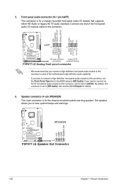
... NC Line out_L PORT1 L PORT1 R PORT2 R SENSE_SEND PORT2 L HD-audio-compliant Legacy AC'97 pin definition compliant definition P5P41T LE Analog front panel connector • We recommend that supports either HD Audio or legacy AC`97 audio standard. See section ...P5P41T LE SPEAKER PIN 1 P5P41T LE Speaker Out Connector 1-22 Chapter 1: Product introduction The speaker allows you connect a high-definition front panel audio module to this connector to avail of the front panel audio I /O module that you to [HD Audio]. Speaker connector (4- Connect one end of the motherboard...
... NC Line out_L PORT1 L PORT1 R PORT2 R SENSE_SEND PORT2 L HD-audio-compliant Legacy AC'97 pin definition compliant definition P5P41T LE Analog front panel connector • We recommend that supports either HD Audio or legacy AC`97 audio standard. See section ...P5P41T LE SPEAKER PIN 1 P5P41T LE Speaker Out Connector 1-22 Chapter 1: Product introduction The speaker allows you connect a high-definition front panel audio module to this connector to avail of the front panel audio I /O module that you to [HD Audio]. Speaker connector (4- Connect one end of the motherboard...


