
User Manual
Page 11
... Duo processors, which are excellent for the following items. Motherboard Cables Accessories Application DVD Documentation ASUS P5P41T LE motherboard 2 x Serial ATA cables 1 x Ultra DMA 100/66/33 cable 1 x I/O shield ASUS motherboard support DVD User Manual 1.3 1.3.1 If any of the above items is damaged or ... and enthusiastic gamers with 1333/ 1066/ 800 MHz FSB. The motherboard delivers a host of ASUS quality motherboards! Before you for buying an ASUS® P5P41T LE motherboard! Thank you start installing the motherboard, and hardware devices on it another standout in the...
... Duo processors, which are excellent for the following items. Motherboard Cables Accessories Application DVD Documentation ASUS P5P41T LE motherboard 2 x Serial ATA cables 1 x Ultra DMA 100/66/33 cable 1 x I/O shield ASUS motherboard support DVD User Manual 1.3 1.3.1 If any of the above items is damaged or ... and enthusiastic gamers with 1333/ 1066/ 800 MHz FSB. The motherboard delivers a host of ASUS quality motherboards! Before you for buying an ASUS® P5P41T LE motherboard! Thank you start installing the motherboard, and hardware devices on it another standout in the...

User Manual
Page 13
... reboot the system. eliminates the need to their default settings. This is subject to convert your screen. ASUS P5P41T LE 1-3 Green ASUS This motherboard and its packaging comply with the ASUS vision of Hazardous Substances (RoHS). Simply shut down and reboot the system, and the BIOS automatically restores ...the CPU parameters to open the system chassis and clear the RTC data. ASUS AI NET2 ASUS AI NET2 remotely detects the cable connection immediately after turning on your favorite photo into a 256-color boot logo for ...
... reboot the system. eliminates the need to their default settings. This is subject to convert your screen. ASUS P5P41T LE 1-3 Green ASUS This motherboard and its packaging comply with the ASUS vision of Hazardous Substances (RoHS). Simply shut down and reboot the system, and the BIOS automatically restores ...the CPU parameters to open the system chassis and clear the RTC data. ASUS AI NET2 ASUS AI NET2 remotely detects the cable connection immediately after turning on your favorite photo into a 256-color boot logo for ...
User Manual
Page 15
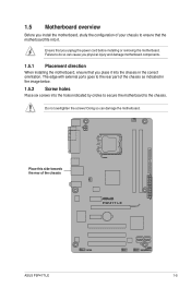
... the motherboard to ensure that you unplug the power cord before installing or removing the motherboard. Place this side towards the rear of the chassis P5P41T LE ASUS P5P41T LE 1-5 The edge with external ports goes to the rear part of the chassis as indicated in the correct orientation. Doing so can cause you physical...
... the motherboard to ensure that you unplug the power cord before installing or removing the motherboard. Place this side towards the rear of the chassis P5P41T LE ASUS P5P41T LE 1-5 The edge with external ports goes to the rear part of the chassis as indicated in the correct orientation. Doing so can cause you physical...
User Manual
Page 17
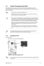
... the cost of repair only if the damage is shipment/transit-related. • Keep the cap after installing the motherboard. ASUS P5P41T LE 1-7 Locate the CPU socket on the LGA775 socket. • The product warranty does not cover damage to the PnP cap/socket contacts/motherboard ...damage to the socket contacts resulting from incorrect CPU installation/removal, or misplacement/loss/incorrect removal of the PnP cap. Contact your left. P5P41T LE P5P41T LE CPU socket 775 Before installing the CPU, ensure that the PnP cap is on the socket and the socket contacts are not bent. The...
... the cost of repair only if the damage is shipment/transit-related. • Keep the cap after installing the motherboard. ASUS P5P41T LE 1-7 Locate the CPU socket on the LGA775 socket. • The product warranty does not cover damage to the PnP cap/socket contacts/motherboard ...damage to the socket contacts resulting from incorrect CPU installation/removal, or misplacement/loss/incorrect removal of the PnP cap. Contact your left. P5P41T LE P5P41T LE CPU socket 775 Before installing the CPU, ensure that the PnP cap is on the socket and the socket contacts are not bent. The...

User Manual
Page 19
... professional medical help. Apply some Thermal Interface Material to the exposed area of the CPU that the heatsink will be in an even thin layer. B ASUS P5P41T LE 1-9 6.
... professional medical help. Apply some Thermal Interface Material to the exposed area of the CPU that the heatsink will be in an even thin layer. B ASUS P5P41T LE 1-9 6.

User Manual
Page 21
... up two fasteners at a time in a diagonal sequence to the connector on the motherboard. 2. CPU_FAN CPU FAN PWM CPU FAN IN CPU FAN PWR GND P5P41T LE P5P41T LE CPU fan connector Do not forget to plug this connector. 1.6.3 Uninstalling the CPU heatsink and fan To uninstall the CPU heatsink and fan: 1. A B A B B A B A ASUS P5P41T LE 1-11
... up two fasteners at a time in a diagonal sequence to the connector on the motherboard. 2. CPU_FAN CPU FAN PWM CPU FAN IN CPU FAN PWR GND P5P41T LE P5P41T LE CPU fan connector Do not forget to plug this connector. 1.6.3 Uninstalling the CPU heatsink and fan To uninstall the CPU heatsink and fan: 1. A B A B B A B A ASUS P5P41T LE 1-11

User Manual
Page 23
... 9 9 9-9-9-24 9 9 6-6-6-20 9 9 6-6-6-20 6-6-6-20 7-7-7-24 9 Voltage 1.65-1.85V 1.65-1.85V 1.60V 1.5V 1.8V 1.8V 1.8V 1.65V DIMM Support A* B ASUS P5P41T LE 1-13 For optimum compatibility, it is the standard way of accessing information from a memory module. Under the default state, some memory modules for the OS... can be about 3GB or less. P5P41T LE Motherboard Qualified Vendors Lists (QVL) DDR3-1333 MHz capability Vendor Part No. 1.7.2 Memory configurations You may operate at a lower ...
... 9 9 9-9-9-24 9 9 6-6-6-20 9 9 6-6-6-20 6-6-6-20 7-7-7-24 9 Voltage 1.65-1.85V 1.65-1.85V 1.60V 1.5V 1.8V 1.8V 1.8V 1.65V DIMM Support A* B ASUS P5P41T LE 1-13 For optimum compatibility, it is the standard way of accessing information from a memory module. Under the default state, some memory modules for the OS... can be about 3GB or less. P5P41T LE Motherboard Qualified Vendors Lists (QVL) DDR3-1333 MHz capability Vendor Part No. 1.7.2 Memory configurations You may operate at a lower ...

User Manual
Page 25
...20 7-7-7-20 9-9-9-24 9 9 7-7-7-20 8-8-8-24 7-7-7-20 8-8-8-24 Voltage 1.5V 1.5V 1.5V 1.5V 1.5V DIMM Support A* B •• DDR3-1066 MHz capability Vendor Part No. ASUS P5P41T LE 1-15 Size SS/ DS Brand Chip NO. Double - Size SS/ DS Brand Chip NO. sided DIMM support: • A*: Supports one module inserted into any slot.... • B*: Supports one pair of modules inserted into the two blue slots as one pair of Dual-channel memory configuration Visit the ASUS website at www.asus.com for the latest QVL. DDR3-1333 MHz capability Vendor Part No.
...20 7-7-7-20 9-9-9-24 9 9 7-7-7-20 8-8-8-24 7-7-7-20 8-8-8-24 Voltage 1.5V 1.5V 1.5V 1.5V 1.5V DIMM Support A* B •• DDR3-1066 MHz capability Vendor Part No. ASUS P5P41T LE 1-15 Size SS/ DS Brand Chip NO. Double - Size SS/ DS Brand Chip NO. sided DIMM support: • A*: Supports one module inserted into any slot.... • B*: Supports one pair of modules inserted into the two blue slots as one pair of Dual-channel memory configuration Visit the ASUS website at www.asus.com for the latest QVL. DDR3-1333 MHz capability Vendor Part No.
User Manual
Page 27
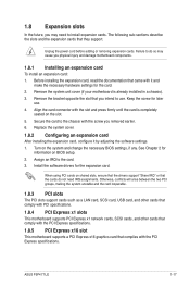
... card. 3. When using PCI cards on the system and change the necessary BIOS settings, if any. Remove the bracket opposite the slot that they support. ASUS P5P41T LE 1-17 The following sub‑sections describe the slots and the expansion cards that you may cause you removed earlier. 6. Secure the card to the...
... card. 3. When using PCI cards on the system and change the necessary BIOS settings, if any. Remove the bracket opposite the slot that they support. ASUS P5P41T LE 1-17 The following sub‑sections describe the slots and the expansion cards that you may cause you removed earlier. 6. Secure the card to the...

User Manual
Page 29
... Mic In 4-channel Rear Speaker Out Front Speaker Out Mic In 6-channel Rear Speaker Out Front Speaker Out Bass/Center 7. USB 2.0 ports 3 and 4. COM port. ASUS P5P41T LE 1-19 Line In port (light blue). Line Out port (lime). This port connects to the table below for the function of this port becomes Front...
... Mic In 4-channel Rear Speaker Out Front Speaker Out Mic In 6-channel Rear Speaker Out Front Speaker Out Bass/Center 7. USB 2.0 ports 3 and 4. COM port. ASUS P5P41T LE 1-19 Line In port (light blue). Line Out port (lime). This port connects to the table below for the function of this port becomes Front...

User Manual
Page 31
...(or later version) and provides a minimum power of 400 W. • Do not forget to connect the 4-pin ATX12V power plug. ASUS P5P41T LE 1-21 The system may become unstable or may not boot up if the power is inadequate. 4. Serial ATA connectors (7-pin SATA1-4) These...RSATA_RXN1 RSATA_RXP1 GND RSATA_TXN1 RSATA_TXP1 GND GND RSATA_RXN2 RSATA_RXP2 GND RSATA_TXN2 RSATA_TXP2 GND P5P41T LE SATA3 SATA4 GND RSATA_RXN3 RSATA_RXP3 GND RSATA_TXN3 RSATA_TXP3 GND GND RSATA_RXN4 RSATA_RXP4 GND RSATA_TXN4 RSATA_TXP4 GND P5P41T LE SATA connectors Install the Windows® XP Service Pack 2 or later ...
...(or later version) and provides a minimum power of 400 W. • Do not forget to connect the 4-pin ATX12V power plug. ASUS P5P41T LE 1-21 The system may become unstable or may not boot up if the power is inadequate. 4. Serial ATA connectors (7-pin SATA1-4) These...RSATA_RXN1 RSATA_RXP1 GND RSATA_TXN1 RSATA_TXP1 GND GND RSATA_RXN2 RSATA_RXP2 GND RSATA_TXN2 RSATA_TXP2 GND P5P41T LE SATA3 SATA4 GND RSATA_RXN3 RSATA_RXP3 GND RSATA_TXN3 RSATA_TXP3 GND GND RSATA_RXN4 RSATA_RXP4 GND RSATA_TXN4 RSATA_TXP4 GND P5P41T LE SATA connectors Install the Windows® XP Service Pack 2 or later ...

User Manual
Page 33
... ribbon cable to configure your device. IDE connector (40-1 pin PRI_IDE) The onboard IDE connector is for Ultra DMA 100/66/33 IDE devices. ASUS P5P41T LE 1-23 Connect the blue connector to the motherboard's IDE connector, then select one of device(s) Master Slave Master Slave Cable connector Black Black Gray Black... or gray • Pin 20 on the IDE connector is set as "Cable-Select," ensure that all other device jumpers have the same setting. P5P41T LE IDE connector If any device jumper is removed to match the covered hole on each Ultra DMA 100/66/33 signal cable: blue, black, and...
... ribbon cable to configure your device. IDE connector (40-1 pin PRI_IDE) The onboard IDE connector is for Ultra DMA 100/66/33 IDE devices. ASUS P5P41T LE 1-23 Connect the blue connector to the motherboard's IDE connector, then select one of device(s) Master Slave Master Slave Cable connector Black Black Gray Black... or gray • Pin 20 on the IDE connector is set as "Cable-Select," ensure that all other device jumpers have the same setting. P5P41T LE IDE connector If any device jumper is removed to match the covered hole on each Ultra DMA 100/66/33 signal cable: blue, black, and...

User Manual
Page 35
... comply with USB 2.0 specification that supports up to the USB connectors. ASUS P5P41T LE 1-25 Doing so will damage the motherboard! 9. USB56 USB78 USB+5V USB_P6USB_P6+ GND NC USB+5V USB_P8USB_P8+ GND NC P5P41T LE PIN 1 PIN 1 USB+5V USB_P5USB_P5+ GND USB+5V USB_P7USB_P7+ GND P5P41T LE USB2.0 connectors Never connect a 1394 cable to 480 Mbps connection...
... comply with USB 2.0 specification that supports up to the USB connectors. ASUS P5P41T LE 1-25 Doing so will damage the motherboard! 9. USB56 USB78 USB+5V USB_P6USB_P6+ GND NC USB+5V USB_P8USB_P8+ GND NC P5P41T LE PIN 1 PIN 1 USB+5V USB_P5USB_P5+ GND USB+5V USB_P7USB_P7+ GND P5P41T LE USB2.0 connectors Never connect a 1394 cable to 480 Mbps connection...
User Manual
Page 37
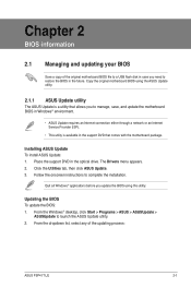
.... The Drivers menu appears. 2. Quit all Windows® applications before you update the BIOS using the ASUS Update utility. 2.1.1 ASUS Update utility The ASUS Update is available in the support DVD that comes with the motherboard package. Updating the BIOS To update the...BIOS in the future. Chapter 2 BIOS information 2.1 Managing and updating your BIOS Save a copy of the updating process: ASUS P5P41T LE 2-1 Installing ASUS Update To install ASUS Update: 1. Follow the onscreen instructions to manage, save, and update the motherboard BIOS in the optical drive. Copy ...
.... The Drivers menu appears. 2. Quit all Windows® applications before you update the BIOS using the ASUS Update utility. 2.1.1 ASUS Update utility The ASUS Update is available in the support DVD that comes with the motherboard package. Updating the BIOS To update the...BIOS in the future. Chapter 2 BIOS information 2.1 Managing and updating your BIOS Save a copy of the updating process: ASUS P5P41T LE 2-1 Installing ASUS Update To install ASUS Update: 1. Follow the onscreen instructions to manage, save, and update the motherboard BIOS in the optical drive. Copy ...

User Manual
Page 39
.... 4. Doing so can restore a corrupted BIOS file using the motherboard support DVD or a removable device that allows you to prevent system boot failure! 2.1.3 ASUS CrashFree BIOS The ASUS CrashFree BIOS is an auto recovery tool that contains the updated BIOS file. • Before using this utility, rename the BIOS file in the... without the floppy connector, prepare a USB flash disk before using this utility. Recovering the BIOS To recover the BIOS: 1. You can cause system boot failure! ASUS P5P41T LE 2-3 2. The utility automatically checks the devices for details.
.... 4. Doing so can restore a corrupted BIOS file using the motherboard support DVD or a removable device that allows you to prevent system boot failure! 2.1.3 ASUS CrashFree BIOS The ASUS CrashFree BIOS is an auto recovery tool that contains the updated BIOS file. • Before using this utility, rename the BIOS file in the... without the floppy connector, prepare a USB flash disk before using this utility. Recovering the BIOS To recover the BIOS: 1. You can cause system boot failure! ASUS P5P41T LE 2-3 2. The utility automatically checks the devices for details.

User Manual
Page 41
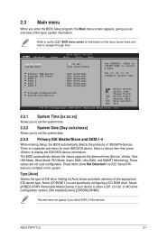
... the bottom right corner of the screen has the following main items: Main For changing the basic system configuration. To change the value of options. ASUS P5P41T LE 2-5 Some of the navigation keys differ from one screen to display a list of the field opposite the item. Power For changing the advanced power management...
... the bottom right corner of the screen has the following main items: Main For changing the basic system configuration. To change the value of options. ASUS P5P41T LE 2-5 Some of the navigation keys differ from one screen to display a list of the field opposite the item. Power For changing the advanced power management...
User Manual
Page 43
...] SATA 1 :[Not Detected] SATA 2 :[Not Detected] SATA 3 :[Not Detected] SATA 4 :[Not Detected] Storage Configuration System Information Use [+] or [-] to display the IDE/SATA device information. ASUS P5P41T LE 2-7 Select a device item then press to configure system time. Type [Auto] Selects the type of the appropriate IDE device type. There is a separate sub-menu...
...] SATA 1 :[Not Detected] SATA 2 :[Not Detected] SATA 3 :[Not Detected] SATA 4 :[Not Detected] Storage Configuration System Information Use [+] or [-] to display the IDE/SATA device information. ASUS P5P41T LE 2-7 Select a device item then press to configure system time. Type [Auto] Selects the type of the appropriate IDE device type. There is a separate sub-menu...

User Manual
Page 45
... field values can cause the system to change the settings for the CPU and other system devices. loads the optimal settings for stability when overclocking. ASUS P5P41T LE 2-9 AI Overclocking [Auto] Allows selection of the general system specifications. System Memory Displays the auto-detected system memory. 2.4 Advanced menu The Advanced menu items allow...
... field values can cause the system to change the settings for the CPU and other system devices. loads the optimal settings for stability when overclocking. ASUS P5P41T LE 2-9 AI Overclocking [Auto] Allows selection of the general system specifications. System Memory Displays the auto-detected system memory. 2.4 Advanced menu The Advanced menu items allow...

User Manual
Page 47
... Support. Ratio CMOS Setting [Auto] Sets the ratio between CPU core clock and the FSB frequency. Press / to adjust the value. Configuration options: [Disabled] [Enabled] ASUS P5P41T LE 2-11 Press / to adjust the value. Valid value is 6.25mv. Configuration options: [1.5V] [1.6V] Setting a very high voltage may damage the component permanently, and setting...
... Support. Ratio CMOS Setting [Auto] Sets the ratio between CPU core clock and the FSB frequency. Press / to adjust the value. Configuration options: [Disabled] [Enabled] ASUS P5P41T LE 2-11 Press / to adjust the value. Valid value is 6.25mv. Configuration options: [1.5V] [1.6V] Setting a very high voltage may damage the component permanently, and setting...

User Manual
Page 49
... [IRQ7] Allows you to select the Parallel Port base addresses. If no USB device is set the Parallel Port ECP DMA. Configuration options: [Enabled] [Disabled] ASUS P5P41T LE 2-13 Select an item then press to [Enabled] or [Auto]. Configuration options: [Disabled] [Enabled] USB 2.0 Controller [Enabled] Allows you to enable or disable the onboard...
... [IRQ7] Allows you to select the Parallel Port base addresses. If no USB device is set the Parallel Port ECP DMA. Configuration options: [Enabled] [Disabled] ASUS P5P41T LE 2-13 Select an item then press to [Enabled] or [Auto]. Configuration options: [Disabled] [Enabled] USB 2.0 Controller [Enabled] Allows you to enable or disable the onboard...


