
User Manual
Page 1
P5P41T LE Motherboard
P5P41T LE Motherboard
User Manual
Page 3
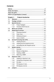
Contents Notices...vi Safety information vii About this guide viii P5P41T LE specifications summary ix Chapter 1: Product introduction 1.1 Welcome 1-1 1.2 Package contents 1-1 1.3 Special features 1-1 1.3.1 Product highlights 1-1 1.3.2 Innovative ASUS features 1-2 1.4 Before you proceed 1-4 1.5 Motherboard overview 1-5 1.5.1 Placement direction 1-5 1.5.2 Screw holes 1-5 1.5.3 Motherboard layout 1-6 1.5.4 Layout contents 1-6 1.6 Central Processing Unit (CPU 1-7 1.6.1 Installing the CPU 1-7 1.6.2 Installing the CPU heatsink ...
Contents Notices...vi Safety information vii About this guide viii P5P41T LE specifications summary ix Chapter 1: Product introduction 1.1 Welcome 1-1 1.2 Package contents 1-1 1.3 Special features 1-1 1.3.1 Product highlights 1-1 1.3.2 Innovative ASUS features 1-2 1.4 Before you proceed 1-4 1.5 Motherboard overview 1-5 1.5.1 Placement direction 1-5 1.5.2 Screw holes 1-5 1.5.3 Motherboard layout 1-6 1.5.4 Layout contents 1-6 1.6 Central Processing Unit (CPU 1-7 1.6.1 Installing the CPU 1-7 1.6.2 Installing the CPU heatsink ...
User Manual
Page 8
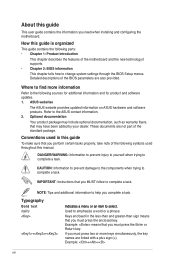
... perform certain tasks properly, take note of the motherboard and the new technology it �e�m�t�o�s�e�le�c�t. IMPORTANT: Instructions that you must press the enclosed key. Italics Used to complete a task. Example: ++ viii...Chapter 2: BIOS information This chapter tells how to help you need when installing and configuring the motherboard. ASUS websites The ASUS website provides updated information on ASUS hardware and software products. Conventions used throughout this guide To make sure that you must press the Enter...
... perform certain tasks properly, take note of the motherboard and the new technology it �e�m�t�o�s�e�le�c�t. IMPORTANT: Instructions that you must press the enclosed key. Italics Used to complete a task. Example: ++ viii...Chapter 2: BIOS information This chapter tells how to help you need when installing and configuring the motherboard. ASUS websites The ASUS website provides updated information on ASUS hardware and software products. Conventions used throughout this guide To make sure that you must press the Enter...

User Manual
Page 9
... total memory of 4GB capacity or more, Windows® 32-bit operating system may only recognize less than 3GB. Supports up to www.asus.com for Intel® CPU support list Northbridge: Intel® G41 Southbridge: Intel® ICH7 1333/1066/800MHz Dual-channel memory architecture... - 2 x 240-pin DIMM sockets support unbuffered non-ECC DDR3 1333 (O.C.)/1066/800MHz memory modules - P5P41T LE specifications summary CPU Chipset System bus Memory Expansion slots Storage LAN Audio LGA775 Socket for Intel® C��o�re�™...
... total memory of 4GB capacity or more, Windows® 32-bit operating system may only recognize less than 3GB. Supports up to www.asus.com for Intel® CPU support list Northbridge: Intel® G41 Southbridge: Intel® ICH7 1333/1066/800MHz Dual-channel memory architecture... - 2 x 240-pin DIMM sockets support unbuffered non-ECC DDR3 1333 (O.C.)/1066/800MHz memory modules - P5P41T LE specifications summary CPU Chipset System bus Memory Expansion slots Storage LAN Audio LGA775 Socket for Intel® C��o�re�™...

User Manual
Page 10
P5P41T LE specifications summary Rear panel ports Internal connectors BIOS features Manageability Accessories Support DVD Form factor 1 x PS/2 keyboard port 1 x PS/2 mouse port 1 x LAN (RJ-45) port 4 x ... v2.5, ACPI v2 0a WOL, PXE, WOR by Ring, PME Wake Up 1 x UltraDMA 100/66/33 cable 2 x Serial ATA cables 1 x I/O shield User Manual Drivers ASUS Update ASUS PC Probe II Anti-virus software (OEM version) ATX form factor: 12 in x7.2 in (30.5 cm x 18.3cm) *Specifications are subject to change without...
P5P41T LE specifications summary Rear panel ports Internal connectors BIOS features Manageability Accessories Support DVD Form factor 1 x PS/2 keyboard port 1 x PS/2 mouse port 1 x LAN (RJ-45) port 4 x ... v2.5, ACPI v2 0a WOL, PXE, WOR by Ring, PME Wake Up 1 x UltraDMA 100/66/33 cable 2 x Serial ATA cables 1 x I/O shield User Manual Drivers ASUS Update ASUS PC Probe II Anti-virus software (OEM version) ATX form factor: 12 in x7.2 in (30.5 cm x 18.3cm) *Specifications are subject to change without...

User Manual
Page 11
... 2 Extreme / Core™ 2 Quad/ Core™ 2 Duo processors, which are excellent for buying an ASUS® P5P41T LE motherboard! Thank you start installing the motherboard, and hardware devices on it another standout in the long line of... following items. Motherboard Cables Accessories Application DVD Documentation ASUS P5P41T LE motherboard 2 x Serial ATA cables 1 x Ultra DMA 100/66/33 cable 1 x I/O shield ASUS motherboard support DVD User Manual 1.3 1.3.1 If any of ASUS quality motherboards! ASUS P5P41T LE 1-1 Chapter 1 Product introduction 1.1 Welcome! The ...
... 2 Extreme / Core™ 2 Quad/ Core™ 2 Duo processors, which are excellent for buying an ASUS® P5P41T LE motherboard! Thank you start installing the motherboard, and hardware devices on it another standout in the long line of... following items. Motherboard Cables Accessories Application DVD Documentation ASUS P5P41T LE motherboard 2 x Serial ATA cables 1 x Ultra DMA 100/66/33 cable 1 x I/O shield ASUS motherboard support DVD User Manual 1.3 1.3.1 If any of ASUS quality motherboards! ASUS P5P41T LE 1-1 Chapter 1 Product introduction 1.1 Welcome! The ...

User Manual
Page 13
... and product models. • Express Gate complies with the OpenGL standard. ASUS CrashFree BIOS 3 ASUS CrashFree BIOS 3 is subject to restore a corrupted BIOS file using an OS-based utility. ASUS P5P41T LE 1-3 feature automatically restores the CPU default settings when the system hangs due ... faulty cable connections are reported back up to their default settings. Green ASUS This motherboard and its packaging comply with the ASUS vision of Hazardous Substances (RoHS). ASUS AI NET2 ASUS AI NET2 remotely detects the cable connection immediately after turning on the use...
... and product models. • Express Gate complies with the OpenGL standard. ASUS CrashFree BIOS 3 ASUS CrashFree BIOS 3 is subject to restore a corrupted BIOS file using an OS-based utility. ASUS P5P41T LE 1-3 feature automatically restores the CPU default settings when the system hangs due ... faulty cable connections are reported back up to their default settings. Green ASUS This motherboard and its packaging comply with the ASUS vision of Hazardous Substances (RoHS). ASUS AI NET2 ASUS AI NET2 remotely detects the cable connection immediately after turning on the use...
User Manual
Page 14
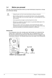
... the power supply. Failure to do so may cause severe damage to indicate that lights up to the motherboard, peripherals, or components. P5P41T LE SB_PWR ON OFF Standby Power Powered Off P5P41T LE Onboard LED 1-4 Chapter 1: Product introduction The illustration below shows the location of the following precautions before you install motherboard components or...
... the power supply. Failure to do so may cause severe damage to indicate that lights up to the motherboard, peripherals, or components. P5P41T LE SB_PWR ON OFF Standby Power Powered Off P5P41T LE Onboard LED 1-4 Chapter 1: Product introduction The illustration below shows the location of the following precautions before you install motherboard components or...
User Manual
Page 15
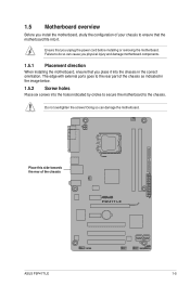
... to do so can damage the motherboard. 1.5 Motherboard overview Before you place it . Ensure that you install the motherboard, study the configuration of the chassis P5P41T LE ASUS P5P41T LE 1-5
... to do so can damage the motherboard. 1.5 Motherboard overview Before you place it . Ensure that you install the motherboard, study the configuration of the chassis P5P41T LE ASUS P5P41T LE 1-5
User Manual
Page 16
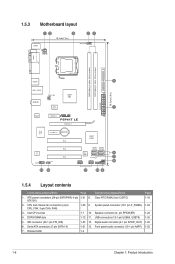
...) DDR3 DIMM_B1 (64bit, 240-pin module) USB34 LGA775 PRI_IDE 5 30.5cm(12.0in) LAN1_USB12 CHA_FAN Intel® G41 AUDIO ICS 9LRS954 1 EATXPWR ATHEROS AR8121 PCIEX1_1 P5P41T LE PCIEX16_1 Super I/O PCIEX1_2 Lithium Cell CMOS Power ALC 662 AAFP SPDIF_OUT 13 12 PCI1 PCI2 PCI3 Intel® ICH7 SATA1 SATA2 SATA3 SATA4 8Mb 6 BIOS...
...) DDR3 DIMM_B1 (64bit, 240-pin module) USB34 LGA775 PRI_IDE 5 30.5cm(12.0in) LAN1_USB12 CHA_FAN Intel® G41 AUDIO ICS 9LRS954 1 EATXPWR ATHEROS AR8121 PCIEX1_1 P5P41T LE PCIEX16_1 Super I/O PCIEX1_2 Lithium Cell CMOS Power ALC 662 AAFP SPDIF_OUT 13 12 PCI1 PCI2 PCI3 Intel® ICH7 SATA1 SATA2 SATA3 SATA4 8Mb 6 BIOS...
User Manual
Page 17
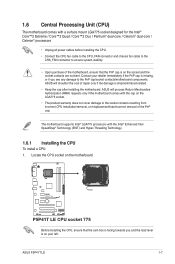
... is on the motherboard. ASUS will process Return Merchandise Authorization (RMA) requests only if the motherboard comes with the Intel® Enhanced Intel SpeedStep® Technology (EIST) and Hyper-Threading Technology. 1.6.1 Installing the CPU To install a CPU: 1. P5P41T LE P5P41T LE CPU socket 775 Before installing... the CPU, ensure that the PnP cap is shipment/transit-related. • Keep the cap after installing the motherboard. ASUS P5P41T LE 1-7 Contact your left. The motherboard supports Intel® LGA775 processors with the cap on your retailer immediately if the PnP...
... is on the motherboard. ASUS will process Return Merchandise Authorization (RMA) requests only if the motherboard comes with the Intel® Enhanced Intel SpeedStep® Technology (EIST) and Hyper-Threading Technology. 1.6.1 Installing the CPU To install a CPU: 1. P5P41T LE P5P41T LE CPU socket 775 Before installing... the CPU, ensure that the PnP cap is shipment/transit-related. • Keep the cap after installing the motherboard. ASUS P5P41T LE 1-7 Contact your left. The motherboard supports Intel® LGA775 processors with the cap on your retailer immediately if the PnP...

User Manual
Page 19
6. To prevent contaminating the paste, DO NOT spread the paste with pre-applied thermal paste. B ASUS P5P41T LE 1-9 DO NOT eat the Thermal Interface Material. Close the load plate (A), then push the load lever (B) until it snaps into your eyes or touches your ...
6. To prevent contaminating the paste, DO NOT spread the paste with pre-applied thermal paste. B ASUS P5P41T LE 1-9 DO NOT eat the Thermal Interface Material. Close the load plate (A), then push the load lever (B) until it snaps into your eyes or touches your ...

User Manual
Page 21
... heatsink and fan: 1. Connect the CPU fan cable to connect the CPU fan connector! Disconnect the CPU fan cable from the motherboard. A B A B B A B A ASUS P5P41T LE 1-11 CPU_FAN CPU FAN PWM CPU FAN IN CPU FAN PWR GND P5P41T LE P5P41T LE CPU fan connector Do not forget to the connector on the motherboard. 2. Rotate each fastener counterclockwise. 3. 3.
... heatsink and fan: 1. Connect the CPU fan cable to connect the CPU fan connector! Disconnect the CPU fan cable from the motherboard. A B A B B A B A ASUS P5P41T LE 1-11 CPU_FAN CPU FAN PWM CPU FAN IN CPU FAN PWR GND P5P41T LE P5P41T LE CPU fan connector Do not forget to the connector on the motherboard. 2. Rotate each fastener counterclockwise. 3. 3.
User Manual
Page 22
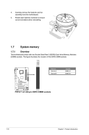
4. The figure illustrates the location of the DDR3 DIMM sockets: DIMM_A1 DIMM_B1 P5P41T LE Channel Channel A Channel B Sockets DIMM_A1 DIMM_B1 P5P41T LE 240-pin DDR3 DIMM sockets 1-12 Chapter 1: Product introduction Rotate each fastener clockwise to ensure correct orientation when reinstalling. 1.7 System memory 1.7.1 Overview The motherboard comes with two Double Data Rate 3 (DDR3) Dual Inline Memory Modules (DIMM) sockets. Carefully remove the heatsink and fan assembly from the motherboard. 5.
4. The figure illustrates the location of the DDR3 DIMM sockets: DIMM_A1 DIMM_B1 P5P41T LE Channel Channel A Channel B Sockets DIMM_A1 DIMM_B1 P5P41T LE 240-pin DDR3 DIMM sockets 1-12 Chapter 1: Product introduction Rotate each fastener clockwise to ensure correct orientation when reinstalling. 1.7 System memory 1.7.1 Overview The motherboard comes with two Double Data Rate 3 (DDR3) Dual Inline Memory Modules (DIMM) sockets. Carefully remove the heatsink and fan assembly from the motherboard. 5.

User Manual
Page 23
... page) Timing DIMM (BIOS) 8-8-8-24 8-8-8-24 9 9 9-9-9-24 9 9 6-6-6-20 9 9 6-6-6-20 6-6-6-20 7-7-7-24 9 Voltage 1.65-1.85V 1.65-1.85V 1.60V 1.5V 1.8V 1.8V 1.8V 1.65V DIMM Support A* B ASUS P5P41T LE 1-13 P5P41T LE Motherboard Qualified Vendors Lists (QVL) DDR3-1333 MHz capability Vendor Part No. Size SS/ DS Brand Chip NO. 1.7.2 Memory configurations You may operate at a lower...
... page) Timing DIMM (BIOS) 8-8-8-24 8-8-8-24 9 9 9-9-9-24 9 9 6-6-6-20 9 9 6-6-6-20 6-6-6-20 7-7-7-24 9 Voltage 1.65-1.85V 1.65-1.85V 1.60V 1.5V 1.8V 1.8V 1.8V 1.65V DIMM Support A* B ASUS P5P41T LE 1-13 P5P41T LE Motherboard Qualified Vendors Lists (QVL) DDR3-1333 MHz capability Vendor Part No. Size SS/ DS Brand Chip NO. 1.7.2 Memory configurations You may operate at a lower...

User Manual
Page 25
... 7-7-7-20 7-7-7-20 9-9-9-24 9 9 7-7-7-20 8-8-8-24 7-7-7-20 8-8-8-24 Voltage 1.5V 1.5V 1.5V 1.5V 1.5V DIMM Support A* B •• DDR3-1066 MHz capability Vendor Part No. Double - ASUS P5P41T LE 1-15 DDR3-1333 MHz capability Vendor Part No. Size SS/ DS Brand Chip NO. sided DIMM support: • A*: Supports one module inserted into any slot...-channel memory configuration. • B*: Supports one pair of modules inserted into the two blue slots as one pair of Dual-channel memory configuration Visit the ASUS website at www.asus.com for the latest QVL.
... 7-7-7-20 7-7-7-20 9-9-9-24 9 9 7-7-7-20 8-8-8-24 7-7-7-20 8-8-8-24 Voltage 1.5V 1.5V 1.5V 1.5V 1.5V DIMM Support A* B •• DDR3-1066 MHz capability Vendor Part No. Double - ASUS P5P41T LE 1-15 DDR3-1333 MHz capability Vendor Part No. Size SS/ DS Brand Chip NO. sided DIMM support: • A*: Supports one module inserted into any slot...-channel memory configuration. • B*: Supports one pair of modules inserted into the two blue slots as one pair of Dual-channel memory configuration Visit the ASUS website at www.asus.com for the latest QVL.
User Manual
Page 27
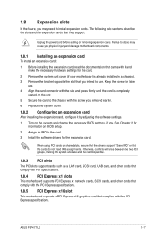
... system and change the necessary BIOS settings, if any. Before installing the expansion card, read the documentation that came with the screw you removed earlier. 6. ASUS P5P41T LE 1-17 Secure the card to the card. 3. The following sub‑sections describe the slots and the expansion cards that the cards do so may...
... system and change the necessary BIOS settings, if any. Before installing the expansion card, read the documentation that came with the screw you removed earlier. 6. ASUS P5P41T LE 1-17 Secure the card to the card. 3. The following sub‑sections describe the slots and the expansion cards that the cards do so may...
User Manual
Page 28
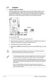
... cause system boot failure! • If the steps above do not need to clear the RTC when the system hangs due to pins 1-2. 3. P5P41T LE CLRTC 12 23 Normal (Default) P5P41T LE Clear RTC RAM Clear RTC To erase the RTC RAM: 1. 1.9 Jumpers 1. You must turn ON the computer. 4. Shut down the key during...
... cause system boot failure! • If the steps above do not need to clear the RTC when the system hangs due to pins 1-2. 3. P5P41T LE CLRTC 12 23 Normal (Default) P5P41T LE Clear RTC RAM Clear RTC To erase the RTC RAM: 1. 1.9 Jumpers 1. You must turn ON the computer. 4. Shut down the key during...

User Manual
Page 29
.... 9. USB 2.0 ports 3 and 4. This 9-pin COM1 port is for connecting USB 2.0 devices. 8. This port is for the LAN port LED indications. PS/2 Keyboard port (purple). ASUS P5P41T LE 1-19 LAN (RJ-45) port. Microphone port (pink). USB 2.0 ports 1 and 2. COM port. PS/2 mouse port (green). Line Out port (lime). This port connects to...
.... 9. USB 2.0 ports 3 and 4. This 9-pin COM1 port is for connecting USB 2.0 devices. 8. This port is for the LAN port LED indications. PS/2 Keyboard port (purple). ASUS P5P41T LE 1-19 LAN (RJ-45) port. Microphone port (pink). USB 2.0 ports 1 and 2. COM port. PS/2 mouse port (green). Line Out port (lime). This port connects to...

User Manual
Page 30
... is purchased separately. 1-20 Chapter 1: Product introduction CPU_FAN CPU FAN PWM CPU FAN IN CPU FAN PWR GND P5P41T LE CHA_FAN GND +12V Rotation P5P41T LE fan connectors Only the 4-pin CPU fan connector supports the ASUS Q-FAN feature. 2. Connect the S/PDIF Out module cable to this connector, then install the module to the fan...
... is purchased separately. 1-20 Chapter 1: Product introduction CPU_FAN CPU FAN PWM CPU FAN IN CPU FAN PWR GND P5P41T LE CHA_FAN GND +12V Rotation P5P41T LE fan connectors Only the 4-pin CPU fan connector supports the ASUS Q-FAN feature. 2. Connect the S/PDIF Out module cable to this connector, then install the module to the fan...


