
User Manual
Page 31
All rights reserved. Reading flash ..... done Write to file...... ok A:\> 當 BIOS DOS 31 Version 1.19(ASUS V2.07(03.11.24BB)) Copyright (C) 2002 American Megatrends, Inc. BIOS 2.1 使用 AFUDOS BIOS AFUDOS DOS BIOS BIOS 程式。AFUDOS BIOS BIOS BIOS 程式 BIOS 程式。 1.2MB BIOS 1 AFUDOS 程式(afudos. exe 2 DOS afudos /o[filename filename A:\>afudos /oOLDBIOS1.rom 3. 按下 afudos /oOLDBIOS1.rom AMI Firmware Update Utility -
All rights reserved. Reading flash ..... done Write to file...... ok A:\> 當 BIOS DOS 31 Version 1.19(ASUS V2.07(03.11.24BB)) Copyright (C) 2002 American Megatrends, Inc. BIOS 2.1 使用 AFUDOS BIOS AFUDOS DOS BIOS BIOS 程式。AFUDOS BIOS BIOS BIOS 程式 BIOS 程式。 1.2MB BIOS 1 AFUDOS 程式(afudos. exe 2 DOS afudos /o[filename filename A:\>afudos /oOLDBIOS1.rom 3. 按下 afudos /oOLDBIOS1.rom AMI Firmware Update Utility -

User Manual
Page 32
... Utility - Do not turn off power during flash BIOS Reading file ....... 更新 BIOS 程式 AFUDOS BIOS 程式。 1 tw.asus.com BIOS 片中。 BIOS BIOS 2. 將 AFUDOS.EXE BIOS 3 DOS afudos /i[filename filename BIOS 程式。 A:\>afudos /iP5B-VM DO.ROM 4. AFUDOS BIOS 程式。 A:\>afudos /iP5B-VM DO.ROM AMI Firmware Update Utility - done...
... Utility - Do not turn off power during flash BIOS Reading file ....... 更新 BIOS 程式 AFUDOS BIOS 程式。 1 tw.asus.com BIOS 片中。 BIOS BIOS 2. 將 AFUDOS.EXE BIOS 3 DOS afudos /i[filename filename BIOS 程式。 A:\>afudos /iP5B-VM DO.ROM 4. AFUDOS BIOS 程式。 A:\>afudos /iP5B-VM DO.ROM AMI Firmware Update Utility - done...

User Manual
Page 33
... Message: Do You Want To Save Bios (Y/N) 33 2.2 使用 AwardBIOS Flash BIOS AwardBIOS Flash AwardBIOS Flash 程式(AWDFLASH.EXE BIOS AwardBIOS Flash BIOS 程式。 1 http://tw.asus.com BIOS M2N-VM HDMI.bin FAT 32/16 格式的 USB BIOS 2 CD/DVD AwardBIOS Flash BIOS 3 DOS 4. 當 A BIOS 檔案與 AwardBIOS Flash 5 A awdflash...
... Message: Do You Want To Save Bios (Y/N) 33 2.2 使用 AwardBIOS Flash BIOS AwardBIOS Flash AwardBIOS Flash 程式(AWDFLASH.EXE BIOS AwardBIOS Flash BIOS 程式。 1 http://tw.asus.com BIOS M2N-VM HDMI.bin FAT 32/16 格式的 USB BIOS 2 CD/DVD AwardBIOS Flash BIOS 3 DOS 4. 當 A BIOS 檔案與 AwardBIOS Flash 5 A awdflash...

User Manual
Page 34
... Name to Continue Write OK F1 Reset No Update Write Fail 34 BIOS PMC Pm49FL004T LPC/FWH File Name to Program: M2A-VM HDMI.bin Flashing Complete Press to Program: M2A-VM HDMI.bin Programming Flash Memory - 7 BIOS N BIOS 8 BIOS BIOS AwardBIOS Flash Utility for ASUS V1.14 (C) Phoenix Technologies Ltd. All Rights Reserved For C51PV-MCP51-M2A...
... Name to Continue Write OK F1 Reset No Update Write Fail 34 BIOS PMC Pm49FL004T LPC/FWH File Name to Program: M2A-VM HDMI.bin Flashing Complete Press to Program: M2A-VM HDMI.bin Programming Flash Memory - 7 BIOS N BIOS 8 BIOS BIOS AwardBIOS Flash Utility for ASUS V1.14 (C) Phoenix Technologies Ltd. All Rights Reserved For C51PV-MCP51-M2A...
User Manual
Page 4
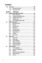
... iv Contents 1.10 Connectors 1-28 1.10.1 Rear panel connectors 1-28 1.10.2 Internal connectors 1-30 Chapter 2: BIOS setup 2.1 Managing and updating your BIOS 2-2 2.1.1 ASUS Update utility 2-2 2.1.2 Creating a bootable floppy disk 2-5 2.1.3 ASUS EZ Flash 2 utility 2-6 2.1.4 AFUDOS utility 2-7 2.1.5 ASUS CrashFree BIOS 3 utility 2-9 2.2 BIOS setup program 2-11 2.2.1 BIOS menu screen 2-12 2.2.2 Menu bar 2-12 2.2.3 Navigation keys 2-12 2.2.4 Menu items 2-13 2.2.5 Sub-menu...
... iv Contents 1.10 Connectors 1-28 1.10.1 Rear panel connectors 1-28 1.10.2 Internal connectors 1-30 Chapter 2: BIOS setup 2.1 Managing and updating your BIOS 2-2 2.1.1 ASUS Update utility 2-2 2.1.2 Creating a bootable floppy disk 2-5 2.1.3 ASUS EZ Flash 2 utility 2-6 2.1.4 AFUDOS utility 2-7 2.1.5 ASUS CrashFree BIOS 3 utility 2-9 2.2 BIOS setup program 2-11 2.2.1 BIOS menu screen 2-12 2.2.2 Menu bar 2-12 2.2.3 Navigation keys 2-12 2.2.4 Menu items 2-13 2.2.5 Sub-menu...
User Manual
Page 8
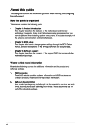
... documentation Your product package may include optional documentation, such as warranty flyers, that you need when installing and configuring the motherboard. ASUS websites The ASUS website provides updated information on the motherboard. • Chapter 2: BIOS setup This chapter tells how to perform when installing system components. These documents are also provided. • Chapter 3: Software support...
... documentation Your product package may include optional documentation, such as warranty flyers, that you need when installing and configuring the motherboard. ASUS websites The ASUS website provides updated information on the motherboard. • Chapter 2: BIOS setup This chapter tells how to perform when installing system components. These documents are also provided. • Chapter 3: Software support...
User Manual
Page 11
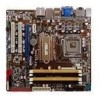
... ATX 12 V power connector 1 x System panel connector (Q-Connector) (continued on the next page) xi vCore: Adjustable CPU voltage at 1MHz increment Overclocking Protection: - SB tuning from 133 to 2 PATA devices Realtek® ALC1200 8-channel High-Definition Audio CODEC EPU-4 Engine Express Gate ASUS CrashFree BIOS 3 ASUS Q-Fan 2 ASUS MyLogo 2 ASUS O.C. Profile AI NAP ASUS Q-connector Precision Tweaker: - P5N7A-VM...
... ATX 12 V power connector 1 x System panel connector (Q-Connector) (continued on the next page) xi vCore: Adjustable CPU voltage at 1MHz increment Overclocking Protection: - SB tuning from 133 to 2 PATA devices Realtek® ALC1200 8-channel High-Definition Audio CODEC EPU-4 Engine Express Gate ASUS CrashFree BIOS 3 ASUS Q-Fan 2 ASUS MyLogo 2 ASUS O.C. Profile AI NAP ASUS Q-connector Precision Tweaker: - P5N7A-VM...
User Manual
Page 12
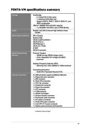
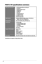
...P5N7A-VM specifications summary Rear panel connectors BIOS features Manageability Accessories Support DVD contents Form factor 1 x PS/2 keyboard/mouse combo port 1 x VGA port 1 x Optical S/PDIF Out port 1 x DisplayPort 1 x HDMI port 1 x DVI port 1 x External SATA port 1 x LAN (RJ-45) port 6 x USB 2.0/1.1 ports 8-channel audio ports 8 Mb Flash ROM, AMI BIOS...v2.0a, SM BIOS 2.5 WOL, PXE, WOR by Ring, PME Wake Up 2 x SATA cables 1 x 2-port SATA power cable 1 x UltraDMA 133/100 cable 1 x I/O Shield 1 x 2 in 1 Q-connector User guide Express Gate Drivers ASUS PC Probe II ASUS Update Image Editing ...
...P5N7A-VM specifications summary Rear panel connectors BIOS features Manageability Accessories Support DVD contents Form factor 1 x PS/2 keyboard/mouse combo port 1 x VGA port 1 x Optical S/PDIF Out port 1 x DisplayPort 1 x HDMI port 1 x DVI port 1 x External SATA port 1 x LAN (RJ-45) port 6 x USB 2.0/1.1 ports 8-channel audio ports 8 Mb Flash ROM, AMI BIOS...v2.0a, SM BIOS 2.5 WOL, PXE, WOR by Ring, PME Wake Up 2 x SATA cables 1 x 2-port SATA power cable 1 x UltraDMA 133/100 cable 1 x I/O Shield 1 x 2 in 1 Q-connector User guide Express Gate Drivers ASUS PC Probe II ASUS Update Image Editing ...
User Manual
Page 18
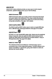
... distribute their favorite settings. 1-6 Chapter 1: Product Introduction See page 2-6 for details. Profile The motherboard features the ASUS O.C. ASUS CrashFree BIOS 3 The ASUS CrashFree BIOS 3 allows users to launch the utility and update the BIOS without preparing a bootable diskette or using an OS-based flash utility. ASUS Q-Connector ASUS Q-Connector allows you easy ways to install computer components, update the...
... distribute their favorite settings. 1-6 Chapter 1: Product Introduction See page 2-6 for details. Profile The motherboard features the ASUS O.C. ASUS CrashFree BIOS 3 The ASUS CrashFree BIOS 3 allows users to launch the utility and update the BIOS without preparing a bootable diskette or using an OS-based flash utility. ASUS Q-Connector ASUS Q-Connector allows you easy ways to install computer components, update the...
User Manual
Page 19
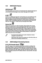
... NET 2 AI NET 2 is the one-stop gateway to instant fun! You can easily monitor the condition of the motherboard BIOS allows automatic re-setting to the BIOS default settings in case the system hangs due to overclocking. When the system hangs due to open the system chassis and ... QQ, and Yahoo! Simply shut down and reboot the system, and the BIOS automatically restores the CPU default setting for details. During the bootup process, AI NET 2 immediately diagnoses the LAN cable and reports shorts and faults up to keep in OS. ASUS P5N7A-VM 1-7 See page 2-34 for each parameter.
... NET 2 AI NET 2 is the one-stop gateway to instant fun! You can easily monitor the condition of the motherboard BIOS allows automatic re-setting to the BIOS default settings in case the system hangs due to overclocking. When the system hangs due to open the system chassis and ... QQ, and Yahoo! Simply shut down and reboot the system, and the BIOS automatically restores the CPU default setting for details. During the bootup process, AI NET 2 immediately diagnoses the LAN cable and reports shorts and faults up to keep in OS. ASUS P5N7A-VM 1-7 See page 2-34 for each parameter.
User Manual
Page 22
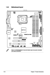
...,240-pin module) LPT EATXPWR FLOPPY 24.4cm (9.6in) 1.5.3 Motherboard layout 23.4cm (9.2in) KB/MS_USB56 SPDIFO_ HDMI_ DP_ ATX12V LGA775 PWR_FAN CPU_FAN Super I/O COM1 VGA_DVI F_ ESATA_ USB34 LAN1_USB12 CHA_FAN AUDIO 8Mb BIOS MCP7A-S CLRTC PCIEX1_1 CR2032 3V Lithium Cell CMOS Power P5N7A-VM RTL 8211CL PCIEX16 PRI_IDE ALC1200 SPDIF_OUT AAFP PCI1 PCI2...
...,240-pin module) LPT EATXPWR FLOPPY 24.4cm (9.6in) 1.5.3 Motherboard layout 23.4cm (9.2in) KB/MS_USB56 SPDIFO_ HDMI_ DP_ ATX12V LGA775 PWR_FAN CPU_FAN Super I/O COM1 VGA_DVI F_ ESATA_ USB34 LAN1_USB12 CHA_FAN AUDIO 8Mb BIOS MCP7A-S CLRTC PCIEX1_1 CR2032 3V Lithium Cell CMOS Power P5N7A-VM RTL 8211CL PCIEX16 PRI_IDE ALC1200 SPDIF_OUT AAFP PCI1 PCI2...
User Manual
Page 36
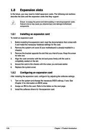
...the chassis with the screw you may cause you intend to the tables on the system and change the necessary BIOS settings, if any. Install the software drivers for later use . 1.8 Expansion slots In the future, you ...cards. See Chapter 2 for the card. 2. Remove the bracket opposite the slot that you physical injury and damage motherboard components. 1.8.1 Installing an expansion card To install an expansion card: 1. Replace the system cover. 1.8.2 Configuring an ... in a chassis). 3. Remove the system unit cover (if your motherboard is completely seated on BIOS setup. 2.
...the chassis with the screw you may cause you intend to the tables on the system and change the necessary BIOS settings, if any. Install the software drivers for later use . 1.8 Expansion slots In the future, you ...cards. See Chapter 2 for the card. 2. Remove the bracket opposite the slot that you physical injury and damage motherboard components. 1.8.1 Installing an expansion card To install an expansion card: 1. Replace the system cover. 1.8.2 Configuring an ... in a chassis). 3. Remove the system unit cover (if your motherboard is completely seated on BIOS setup. 2.
User Manual
Page 39
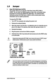
...default position. Removing the cap will cause system boot failure! ASUS P5N7A-VM 1-27 You can automatically reset parameter settings to default values. Move the jumper cap from pins 1-2 (default) to pins 1-2. 4. Hold down and reboot the system so the BIOS can clear the CMOS memory of date, time, and system...2-3 for about 5~10 seconds, then move the cap back to pins 2-3. The onboard button cell battery powers the RAM data in CMOS. P5N7A-VM P5N7A-VM Clear RTC RAM CLRTC 12 23 Normal (Default) Clear RTC You do not need to clear the RTC when the system hangs due to ...
...default position. Removing the cap will cause system boot failure! ASUS P5N7A-VM 1-27 You can automatically reset parameter settings to default values. Move the jumper cap from pins 1-2 (default) to pins 1-2. 4. Hold down and reboot the system so the BIOS can clear the CMOS memory of date, time, and system...2-3 for about 5~10 seconds, then move the cap back to pins 2-3. The onboard button cell battery powers the RAM data in CMOS. P5N7A-VM P5N7A-VM Clear RTC RAM CLRTC 12 23 Normal (Default) Clear RTC You do not need to clear the RTC when the system hangs due to ...
User Manual
Page 41
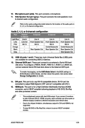
... RAID0, RAID1, RAID 0+1, RAID 5, or JBOD set the SATA Mode Select in the BIOS settings to [RAID Mode] or [AHCI Mode], and then reboot the system. See section 2.3.5 Storage Configuration for connecting USB 2.0 devices. 13. ASUS P5N7A-VM 1-29 This port connects the side speakers in 2, 4, 6, or 8-channel configuration. USB... an 8-channel audio configuration. This port is for the function of HD DVD, Blu-Ray and other protected content. • This motherboard comes with DVI-I. 15. Refer to the External SATA port. This port is not supported. • To play HD DVD or Blu...
... RAID0, RAID1, RAID 0+1, RAID 5, or JBOD set the SATA Mode Select in the BIOS settings to [RAID Mode] or [AHCI Mode], and then reboot the system. See section 2.3.5 Storage Configuration for connecting USB 2.0 devices. 13. ASUS P5N7A-VM 1-29 This port connects the side speakers in 2, 4, 6, or 8-channel configuration. USB... an 8-channel audio configuration. This port is for the function of HD DVD, Blu-Ray and other protected content. • This motherboard comes with DVI-I. 15. Refer to the External SATA port. This port is not supported. • To play HD DVD or Blu...

User Manual
Page 48
...or switch sends a high-level signal to use the chassis intrusion detection feature. +5VSB_MB Chassis Signal GND P5N7A-VM P5N7A-VM Intrusion Connector CHASSIS (Default) 11. 10. Connect one end of the motherboard's high-definition audio capability. • If you want to connect an AC'97 front panel audio ...module to this connector is set the Front Panel Type item in the BIOS setup to [HD Audio]. Chassis intrusion connector (4-1 pin...
...or switch sends a high-level signal to use the chassis intrusion detection feature. +5VSB_MB Chassis Signal GND P5N7A-VM P5N7A-VM Intrusion Connector CHASSIS (Default) 11. 10. Connect one end of the motherboard's high-definition audio capability. • If you want to connect an AC'97 front panel audio ...module to this connector is set the Front Panel Type item in the BIOS setup to [HD Audio]. Chassis intrusion connector (4-1 pin...
User Manual
Page 50
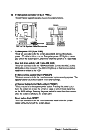
...you turn on the BIOS settings. Connect the HDD Activity LED cable to this connector. Pressing the power button turns the system on or puts the system in sleep or soft-off the system power. 1-38 Chapter 1: Product Introduction PWR Ground Reset Ground +IDE_LED P5N7A-VM System Panel Connector Reset... PWRSW • System power LED (2-pin PLED) This 2-pin connector is for the HDD Activity LED. The system power LED lights up or flashes when data is read from or written to hear system beeps and warnings. • ATX power button/...
...you turn on the BIOS settings. Connect the HDD Activity LED cable to this connector. Pressing the power button turns the system on or puts the system in sleep or soft-off the system power. 1-38 Chapter 1: Product Introduction PWR Ground Reset Ground +IDE_LED P5N7A-VM System Panel Connector Reset... PWRSW • System power LED (2-pin PLED) This 2-pin connector is for the HDD Activity LED. The system power LED lights up or flashes when data is read from or written to hear system beeps and warnings. • ATX power button/...
User Manual
Page 53
Detailed descriptions of the BIOS parameters are also provided. This chapter tells how to change the system settings through the BIOS Setup menus. Chapter 2: 2 BIOS setup
Detailed descriptions of the BIOS parameters are also provided. This chapter tells how to change the system settings through the BIOS Setup menus. Chapter 2: 2 BIOS setup

User Manual
Page 54
... the Utilities tab, then click Install ASUS Update. 3. 2.1 Managing and updating your BIOS The following utilities allow you to your system. 2-2 Chapter 2: BIOS setup ASUS CrashFree BIOS 3: Updates the BIOS using the ASUS Update or AFUDOS utilities. 2.1.1 ASUS Update utility The ASUS Update is copied to manage and update the motherboard Basic Input/Output System (BIOS) setup. 1. Place the support DVD...
... the Utilities tab, then click Install ASUS Update. 3. 2.1 Managing and updating your BIOS The following utilities allow you to your system. 2-2 Chapter 2: BIOS setup ASUS CrashFree BIOS 3: Updates the BIOS using the ASUS Update or AFUDOS utilities. 2.1.1 ASUS Update utility The ASUS Update is copied to manage and update the motherboard Basic Input/Output System (BIOS) setup. 1. Place the support DVD...
User Manual
Page 55
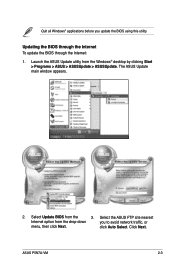
Quit all Windows® applications before you to avoid network traffic, or menu, then click Next. Launch the ASUS Update utility from the drop‑down you update the BIOS using this utility. Select the ASUS FTP site nearest Internet option from the Windows® desktop by clicking Start > Programs > ASUS > ASUSUpdate > ASUSUpdate. The ASUS Update main window appears. 2. Select Update BIOS from the 3. Click Next. click Auto Select. ASUS P5N7A-VM 2-3 Updating the BIOS through the Internet To update the BIOS through the Internet: 1.
Quit all Windows® applications before you to avoid network traffic, or menu, then click Next. Launch the ASUS Update utility from the drop‑down you update the BIOS using this utility. Select the ASUS FTP site nearest Internet option from the Windows® desktop by clicking Start > Programs > ASUS > ASUSUpdate > ASUSUpdate. The ASUS Update main window appears. 2. Select Update BIOS from the 3. Click Next. click Auto Select. ASUS P5N7A-VM 2-3 Updating the BIOS through the Internet To update the BIOS through the Internet: 1.
User Manual
Page 56
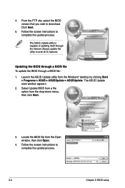
... utility from the drop‑down menu, then click Next. 3. Follow the screen instructions to download. The ASUS Update main window appears. 2. P5N7AVM.rom P5N7AVM 2-4 Chapter 2: BIOS setup Updating the BIOS through a BIOS file To update the BIOS through the Internet. Select Update BIOS from a file option from the Windows® desktop by clicking Start > Programs...
... utility from the drop‑down menu, then click Next. 3. Follow the screen instructions to download. The ASUS Update main window appears. 2. P5N7AVM.rom P5N7AVM 2-4 Chapter 2: BIOS setup Updating the BIOS through a BIOS file To update the BIOS through the Internet. Select Update BIOS from a file option from the Windows® desktop by clicking Start > Programs...


