User Manual
Page 5
... Chapter 6: Driver installation 6.1 RAID driver installation 6-1 6.1.1 Creating a RAID driver disk 6-1 6.1.2 Installing the Intel® ICH7R RAID controller driver .... 6-3 6.2 LAN driver installation 6-7 6.2.1 Windows® 2000/2003 Server 6-7 6.2.2 Red Hat® Linux 9.0 6-9 6.3 VGA driver installation 6-11 6.3.1 Windows® 2000 Server 6-11 6.3.2 Windows® 2003 Server 6-12 6.3.3 Red Hat® Linux 9.0 6-12 Appendix: Reference information...
... Chapter 6: Driver installation 6.1 RAID driver installation 6-1 6.1.1 Creating a RAID driver disk 6-1 6.1.2 Installing the Intel® ICH7R RAID controller driver .... 6-3 6.2 LAN driver installation 6-7 6.2.1 Windows® 2000/2003 Server 6-7 6.2.2 Red Hat® Linux 9.0 6-9 6.3 VGA driver installation 6-11 6.3.1 Windows® 2000 Server 6-11 6.3.2 Windows® 2003 Server 6-12 6.3.3 Red Hat® Linux 9.0 6-12 Appendix: Reference information...
User Manual
Page 10
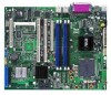
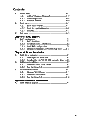
...-PCI socket for ASUS® Server Management Board ATI® RAGE-XL PCI-based VGA controller Dual Broadcom BCM5721 Gigabit LAN controller (PCI Express 1.0a specifications compliant) Intel® ICH7R Southbridge supports: - 8 x USB 2.0 ports (2 on the next page) x P5MT-M specifications summary CPU... architecture 4 x 240-pin DIMM sockets support unbuffered ECC 667/533 MHz DDR2 memory modules Supports 256 MB up to 6 additional ports) ASUS Q-Fan ASUS CrashFree BIOS 2 ASUS MyLogo2™ ASUS EZ FLash AMI BIOS, 8 Mb FWH, Green, PnP, DMI2.0a, ACPI 2.0a, SMBIOS 2.3 1 x PS/2 keyboard port 1...
...-PCI socket for ASUS® Server Management Board ATI® RAGE-XL PCI-based VGA controller Dual Broadcom BCM5721 Gigabit LAN controller (PCI Express 1.0a specifications compliant) Intel® ICH7R Southbridge supports: - 8 x USB 2.0 ports (2 on the next page) x P5MT-M specifications summary CPU... architecture 4 x 240-pin DIMM sockets support unbuffered ECC 667/533 MHz DDR2 memory modules Supports 256 MB up to 6 additional ports) ASUS Q-Fan ASUS CrashFree BIOS 2 ASUS MyLogo2™ ASUS EZ FLash AMI BIOS, 8 Mb FWH, Green, PnP, DMI2.0a, ACPI 2.0a, SMBIOS 2.3 1 x PS/2 keyboard port 1...

User Manual
Page 16
... supports the Serial ATA II technology through the Serial ATA 3 Gb/s RAID controller to ensure data security and enable powerful multi-task processing. The uniprocessor server chipset integrates EM64T support and four Serial ATA ports enabled through the Serial ATA II interfaces controlled by the Intel® ICH7R.
... supports the Serial ATA II technology through the Serial ATA 3 Gb/s RAID controller to ensure data security and enable powerful multi-task processing. The uniprocessor server chipset integrates EM64T support and four Serial ATA ports enabled through the Serial ATA II interfaces controlled by the Intel® ICH7R.
User Manual
Page 28
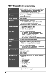
... enable the Hyper-Threading Technology item in the BIOS to ensure system stability and performance. • Installing Windows® 2003 Server or later version is supported under Windows® XP/2003 Server and Linux 2.4.x (kernel) and later versions only. Power up the system and enter the BIOS Setup (see Chapter 4: BIOS setup...
... enable the Hyper-Threading Technology item in the BIOS to ensure system stability and performance. • Installing Windows® 2003 Server or later version is supported under Windows® XP/2003 Server and Linux 2.4.x (kernel) and later versions only. Power up the system and enter the BIOS Setup (see Chapter 4: BIOS setup...
User Manual
Page 34
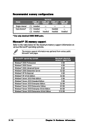
...® XP Professional Windows® XP 64-bit Edition Windows® Server 2003 Web Edition Windows® Server 2003 Standard Edition Windows® Server 2003 Enterprise Edition Windows® Server 2003 Datacenter Edition Windows® Server 2003 Enterprise 64-bit Edition Windows® Server 2003 Datacenter 64-bit Edition Maximum physical memory supported 4 GB 4 GB 8 GB...
...® XP Professional Windows® XP 64-bit Edition Windows® Server 2003 Web Edition Windows® Server 2003 Standard Edition Windows® Server 2003 Enterprise Edition Windows® Server 2003 Datacenter Edition Windows® Server 2003 Enterprise 64-bit Edition Windows® Server 2003 Datacenter 64-bit Edition Maximum physical memory supported 4 GB 4 GB 8 GB...
User Manual
Page 52
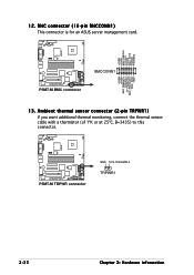
12. BMC connector (16-pin BMCCONN1) This connector is for an ASUS server management card. +5VSB +5VSB BMC SMBCLK 12CCLK1 PSON# BMC_RST# PWROK PSONEN# P5MT-M ® LAN2 BMCCONN1 P5MT-M BMC connector +5VSB +5VSB BMC SMBDATA 12CDATA1 FP_PWRBTN# BMC_PRESENT# BMC_SMI# GND 13. P5MT-M ® LAN2 P5MT-M TRPWR connector GND SYS-THEAMAL2 TRPWR1 2-32 Chapter 2: Hardware information Ambient thermal sensor connector (2-pin TRPWR1) If you want additional thermal monitoring, connect the thermal sensor cable with a thermistor (of 1ºK or at 25ºC, B=3435) to this connector.
12. BMC connector (16-pin BMCCONN1) This connector is for an ASUS server management card. +5VSB +5VSB BMC SMBCLK 12CCLK1 PSON# BMC_RST# PWROK PSONEN# P5MT-M ® LAN2 BMCCONN1 P5MT-M BMC connector +5VSB +5VSB BMC SMBDATA 12CDATA1 FP_PWRBTN# BMC_PRESENT# BMC_SMI# GND 13. P5MT-M ® LAN2 P5MT-M TRPWR connector GND SYS-THEAMAL2 TRPWR1 2-32 Chapter 2: Hardware information Ambient thermal sensor connector (2-pin TRPWR1) If you want additional thermal monitoring, connect the thermal sensor cable with a thermistor (of 1ºK or at 25ºC, B=3435) to this connector.
User Manual
Page 53
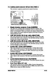
... and is always lit when linked. • LAN2 link activity LED (2-pin LAN2_LINKACTLED) This 2-pin connector is for the LAN1 Activity LED. ASUS P5MT-M 2-33 Connect the LAN2 Activity LED cable to this connector. Connect the Locator LED 1 cable to this connector. 14. the LAN1 controller ...an SMBus host and/or other SMBus devices using the SMBus interface. Auxiliary panel connector (20-pin AUX_PANEL1) This connector supports several server system functions. Connect the LAN1 Activity LED cable to this connector. Connect the Locator LED 2 cable to this connector. This ...
... and is always lit when linked. • LAN2 link activity LED (2-pin LAN2_LINKACTLED) This 2-pin connector is for the LAN1 Activity LED. ASUS P5MT-M 2-33 Connect the LAN2 Activity LED cable to this connector. Connect the Locator LED 1 cable to this connector. 14. the LAN1 controller ...an SMBus host and/or other SMBus devices using the SMBus interface. Auxiliary panel connector (20-pin AUX_PANEL1) This connector supports several server system functions. Connect the LAN1 Activity LED cable to this connector. Connect the Locator LED 2 cable to this connector. This ...
User Manual
Page 58
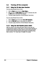
...: 1. Click the T u r n O f f button to shut down . 3.2 Turning off the computer 3.2.1 Using the OS shut down function If you are using Windows® Server 2003: 1. Click the S t a r t button then click S h u t D o w n . . . 2. The power supply should turn off mode, depending on the BIOS setting. Click the S t a r t button then select T u r n O f f C o m p u t e r . 2. Pressing the ...
...: 1. Click the T u r n O f f button to shut down . 3.2 Turning off the computer 3.2.1 Using the OS shut down function If you are using Windows® Server 2003: 1. Click the S t a r t button then click S h u t D o w n . . . 2. The power supply should turn off mode, depending on the BIOS setting. Click the S t a r t button then select T u r n O f f C o m p u t e r . 2. Pressing the ...
User Manual
Page 99
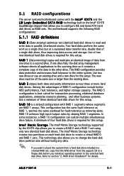
...n t e l® I C H 7 R and the L S I L o g i c E m b e d d e d S A T A R A I D 0 (Data striping) optimizes two identical hard disk drives to section "2. ASUS P5MT-M 5-1 Among the advantages of the same size or larger than the existing drive. This configuration has the same fault tolerance as mirroring alone. In some... applications to create a RAID 0 and a RAID 1 set using only two identical hard disk drives. 5.1 RAID configurations The server system/motherboard comes with RAID 1 segments whose segments are RAID 1 arrays. RAID 1 (Data mirroring) copies and maintains an ...
...n t e l® I C H 7 R and the L S I L o g i c E m b e d d e d S A T A R A I D 0 (Data striping) optimizes two identical hard disk drives to section "2. ASUS P5MT-M 5-1 Among the advantages of the same size or larger than the existing drive. This configuration has the same fault tolerance as mirroring alone. In some... applications to create a RAID 0 and a RAID 1 set using only two identical hard disk drives. 5.1 RAID configurations The server system/motherboard comes with RAID 1 segments whose segments are RAID 1 arrays. RAID 1 (Data mirroring) copies and maintains an ...
User Manual
Page 103
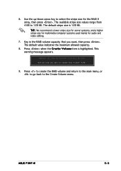
The default stripe size is highlighted. ASUS P5MT-M 5-5 T I P : We recommend a lower stripe size for server systems, and a higher stripe size for multimedia computer systems used mainly for the RAID 0 array, then press . This warning message appears. WARNING: ALL DATA ON ...
The default stripe size is highlighted. ASUS P5MT-M 5-5 T I P : We recommend a lower stripe size for server systems, and a higher stripe size for multimedia computer systems used mainly for the RAID 0 array, then press . This warning message appears. WARNING: ALL DATA ON ...
User Manual
Page 105
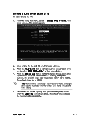
... select R A I D 1 0 ( R A I D L e v e l item is case sensitive and cannot contain special characters. [↑↓]-Change [TAB]-Next [ESC]-Previous Menu [Enter]-Select 2. T I D V o l u m e, then press . ASUS P5MT-M 5-7 C r e a t e R A I P : We recommend a lower stripe size for server systems, and a higher stripe size for multimedia computer systems used to 128 KB. Enter a name for the RAID 10 set : 1. The default...
... select R A I D 1 0 ( R A I D L e v e l item is case sensitive and cannot contain special characters. [↑↓]-Change [TAB]-Next [ESC]-Previous Menu [Enter]-Select 2. T I D V o l u m e, then press . ASUS P5MT-M 5-7 C r e a t e R A I P : We recommend a lower stripe size for server systems, and a higher stripe size for multimedia computer systems used to 128 KB. Enter a name for the RAID 10 set : 1. The default...
User Manual
Page 107
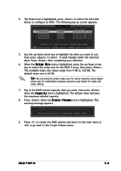
A small triangle marks the selected drive. T I P : We recommend a lower stripe size for server systems, and a higher stripe size for multimedia computer systems used mainly for the RAID 5 array, then press . This warning message appears. Are you sure ...to configure as RAID. The default value indicates the maximum allowed capacity. 8. The default stripe size is highlighted. Press when the C r e a t e V o l u m e item is 64 KB. ASUS P5MT-M 5-9 The Disks item is highlighted, press the up /down arrow key to 128 KB. 4. WARNING: ALL DATA ON SELECTED DISKS WILL BE LOST.
A small triangle marks the selected drive. T I P : We recommend a lower stripe size for server systems, and a higher stripe size for multimedia computer systems used mainly for the RAID 5 array, then press . This warning message appears. Are you sure ...to configure as RAID. The default value indicates the maximum allowed capacity. 8. The default stripe size is highlighted. Press when the C r e a t e V o l u m e item is 64 KB. ASUS P5MT-M 5-9 The Disks item is highlighted, press the up /down arrow key to 128 KB. 4. WARNING: ALL DATA ON SELECTED DISKS WILL BE LOST.
User Manual
Page 115
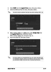
6. When creating a RAID 0 set , select S t r i p e S i z e from the L o g i c a l D r i v e menu, then press . For server systems, we recommend a higher array block size for audio and video editing, we recommend that you use a lower array block size. When creating a RAID 1 or a ... systems used mainly for optimum performance. You need at least two identical hard disk drives when creating a RAID 1 set. 8. Select R A I D from the menu, then press . ASUS P5MT-M 5-17 Select the RAID level from the L o g i c a l D r i v e menu, then press . 7.
6. When creating a RAID 0 set , select S t r i p e S i z e from the L o g i c a l D r i v e menu, then press . For server systems, we recommend a higher array block size for audio and video editing, we recommend that you use a lower array block size. When creating a RAID 1 or a ... systems used mainly for optimum performance. You need at least two identical hard disk drives when creating a RAID 1 set. 8. Select R A I D from the menu, then press . ASUS P5MT-M 5-17 Select the RAID level from the L o g i c a l D r i v e menu, then press . 7.

User Manual
Page 136
Windows® 2000/2003 Server To create a RAID driver disk in the optical drive. 2. Insert a formatted high-density floppy disk to prevent computer virus infection. 6-2 C h a p t e r 6 : Dr i v e r i n s t a l l a t i o n After creating a RAID driver ... locate the driver disk utility. Restart the system from the hard disk drive, then place the system/ motherboard support CD in Windows® 2000/2003 Server environment: 1. The 32-bit OS RAID driver disk for the Intel® ICH7R is located in: \Drivers\Chipset\ICH\Intel\Driver\Makedisk\F6flpy32 The 64...
Windows® 2000/2003 Server To create a RAID driver disk in the optical drive. 2. Insert a formatted high-density floppy disk to prevent computer virus infection. 6-2 C h a p t e r 6 : Dr i v e r i n s t a l l a t i o n After creating a RAID driver ... locate the driver disk utility. Restart the system from the hard disk drive, then place the system/ motherboard support CD in Windows® 2000/2003 Server environment: 1. The 32-bit OS RAID driver disk for the Intel® ICH7R is located in: \Drivers\Chipset\ICH\Intel\Driver\Makedisk\F6flpy32 The 64...
User Manual
Page 137
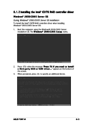
... the bottom of the screen. 3. When prompted, press to specify an additional device. 6.1.2 Installing the Intel® ICH7R RAID controller driver Windows® 2000/2003 Server OS During Windows® 2000/2003 Server OS installation To install the Intel® ICH7R RAID controller driver when installing Windows® 2000/2003 Server OS: 1. ASUS P5MT-M 6-3
... the bottom of the screen. 3. When prompted, press to specify an additional device. 6.1.2 Installing the Intel® ICH7R RAID controller driver Windows® 2000/2003 Server OS During Windows® 2000/2003 Server OS installation To install the Intel® ICH7R RAID controller driver when installing Windows® 2000/2003 Server OS: 1. ASUS P5MT-M 6-3

User Manual
Page 139
Right-click the M y C o m p u t e r icon on an existing Windows® 2000/2003 Server OS: 1. Insert the RAID driver disk you created earlier to display the list of devices installed in the system. 5.... floppy disk drive. 9. To an existing Windows® 2000/2003 Server OS To install the Intel® ICH7R RAID controller driver on the Windows® desktop , then select P r o p e r t i e s from the menu. 4. Windows® automatically detects the RAID controller and displays a N e w H a r d w a r e F o u n d window. ASUS P5MT-M 6-5 Restart the computer, then log on with A d m i n i ...
Right-click the M y C o m p u t e r icon on an existing Windows® 2000/2003 Server OS: 1. Insert the RAID driver disk you created earlier to display the list of devices installed in the system. 5.... floppy disk drive. 9. To an existing Windows® 2000/2003 Server OS To install the Intel® ICH7R RAID controller driver on the Windows® desktop , then select P r o p e r t i e s from the menu. 4. Windows® automatically detects the RAID controller and displays a N e w H a r d w a r e F o u n d window. ASUS P5MT-M 6-5 Restart the computer, then log on with A d m i n i ...
User Manual
Page 141
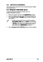
... install the Broadcom® Gigabit LAN controller driver on with A d m i n i s t r a t o r privileges. 2. E X E to the optical drive. ASUS P5MT-M 6-7 Restart the computer, then log on a Windows® 2000/2003 Server OS: 1. The CD automatically displays the D r i v e r s menu if Autorun is NOT enabled in your computer, browse the contents of the support CD to locate the...
... install the Broadcom® Gigabit LAN controller driver on with A d m i n i s t r a t o r privileges. 2. E X E to the optical drive. ASUS P5MT-M 6-7 Restart the computer, then log on a Windows® 2000/2003 Server OS: 1. The CD automatically displays the D r i v e r s menu if Autorun is NOT enabled in your computer, browse the contents of the support CD to locate the...
User Manual
Page 145
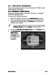
Click the item ATI Rage XL Display Driver from the Drivers menu. 4. ASUS P5MT-M 6-11 Restart the computer, then log on a Windows® 2000 Server operating system. Insert the motherboard/system support CD to close this window. 3. Click C a n c e l to the ... computer. 6.3 VGA driver installation This section provides instructions on how to install the ATI® RAGE XL Video Graphics Adapter (VGA) driver. 6.3.1 Windows® 2000 Server You need to manually install the ATI® RAGE XL VGA driver on with A d m i n i s t r a t o r privileges. 2. Click N e x t. The A T I W i n d o...
Click the item ATI Rage XL Display Driver from the Drivers menu. 4. ASUS P5MT-M 6-11 Restart the computer, then log on a Windows® 2000 Server operating system. Insert the motherboard/system support CD to close this window. 3. Click C a n c e l to the ... computer. 6.3 VGA driver installation This section provides instructions on how to install the ATI® RAGE XL Video Graphics Adapter (VGA) driver. 6.3.1 Windows® 2000 Server You need to manually install the ATI® RAGE XL VGA driver on with A d m i n i s t r a t o r privileges. 2. Click N e x t. The A T I W i n d o...

User Manual
Page 146
Verifying the VGA driver installation To verify if the ATI® RAGE XL VGA drivers are properly installed in a Windows® 2000/2003 Server operating system: 1. The A T I T e c h n o l o g i e s I n c . There is no need to install an ... v e r D e t a i l s button to support the onboard VGA. 6-12 C h a p t e r 6 : Dr i v e r i n s t a l l a t i o n 6.3.2 Windows® 2003 Server The Windows® 2003 Server operating system automatically recognizes the ATI® RAGE XL VGA driver during system installation. Right-click the M y C o m p u t e r icon on the Windows® desktop...
Verifying the VGA driver installation To verify if the ATI® RAGE XL VGA drivers are properly installed in a Windows® 2000/2003 Server operating system: 1. The A T I T e c h n o l o g i e s I n c . There is no need to install an ... v e r D e t a i l s button to support the onboard VGA. 6-12 C h a p t e r 6 : Dr i v e r i n s t a l l a t i o n 6.3.2 Windows® 2003 Server The Windows® 2003 Server operating system automatically recognizes the ATI® RAGE XL VGA driver during system installation. Right-click the M y C o m p u t e r icon on the Windows® desktop...

