
User Manual
Page 16
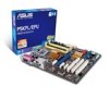
DDR2 DIMM slots 6. Connectors/Jumpers/Slots Clear RTC RAM (3-pin CLRTC) System panel connector (20-8 pin PANEL) 1-23 11. Onboard LED Page 1-21 9. 1-24 10. Front panel audio connector (10-1 pin AAFP) 1-4 16. LGA775 ...
DDR2 DIMM slots 6. Connectors/Jumpers/Slots Clear RTC RAM (3-pin CLRTC) System panel connector (20-8 pin PANEL) 1-23 11. Onboard LED Page 1-21 9. 1-24 10. Front panel audio connector (10-1 pin AAFP) 1-4 16. LGA775 ...

User Manual
Page 28
... Recall (C.P.R.) feature. Turn OFF the computer and unplug the power cord. 2. Move the jumper cap from pins 1-2 (default) to clear the CMOS RTC RAM data. Removing the cap will cause system boot failure! • If the steps above do not need to clear the RTC when the system hangs...system. 1-18 Chapter 1: Product introduction You must turn ON the computer. 4. Keep the cap on CLRTC jumper default position. Except when clearing the RTC RAM, never remove the cap on pins 2-3 for about 5-10 seconds, then move the jumper again to pins 2-3. You can clear the CMOS memory of date...
... Recall (C.P.R.) feature. Turn OFF the computer and unplug the power cord. 2. Move the jumper cap from pins 1-2 (default) to clear the CMOS RTC RAM data. Removing the cap will cause system boot failure! • If the steps above do not need to clear the RTC when the system hangs...system. 1-18 Chapter 1: Product introduction You must turn ON the computer. 4. Keep the cap on CLRTC jumper default position. Except when clearing the RTC RAM, never remove the cap on pins 2-3 for about 5-10 seconds, then move the jumper again to pins 2-3. You can clear the CMOS memory of date...

User Manual
Page 44
... and single partition can change the power management settings. For example, you with the opportunity to force reset from the ASUS website at www.asus.com. 2.2 BIOS setup program This motherboard supports a programmable Serial Peripheral Interface (SPI) chip that the computer can recognize... these changes and record them in the CMOS RAM of your computer in section "2.1 Managing and updating your selections from the operating system....
... and single partition can change the power management settings. For example, you with the opportunity to force reset from the ASUS website at www.asus.com. 2.2 BIOS setup program This motherboard supports a programmable Serial Peripheral Interface (SPI) chip that the computer can recognize... these changes and record them in the CMOS RAM of your computer in section "2.1 Managing and updating your selections from the operating system....

User Manual
Page 55
.... Enables the system to enter the ACPI S3 (Suspend to Enabled, the ACPI APIC table pointer is included in the S1 state. When set to RAM) sleep state (default). When set to [Power Off], the system goes into either off and consumes less power than in the RSDT pointer list. ... you to enable or disable the Advanced Configuration and Power Interface (ACPI) support in a low power mode. Configuration options: [Power Off] [Power On] [Last State] ASUS P5KPL/EPU 2-15 In S1 sleep state, the system appears suspended and stays in the Application-Specific Integrated Circuit (ASIC).
.... Enables the system to enter the ACPI S3 (Suspend to Enabled, the ACPI APIC table pointer is included in the S1 state. When set to RAM) sleep state (default). When set to [Power Off], the system goes into either off and consumes less power than in the RSDT pointer list. ... you to enable or disable the Advanced Configuration and Power Interface (ACPI) support in a low power mode. Configuration options: [Power Off] [Power On] [Last State] ASUS P5KPL/EPU 2-15 In S1 sleep state, the system appears suspended and stays in the Application-Specific Integrated Circuit (ASIC).

User Manual
Page 58
... Configuration options: [Disabled] [Enabled] 2.6.3 Security The Security menu items allow you can clear it by erasing the CMOS Real Time Clock (RTC) RAM. To set to enable or disable support for option ROM. Configuration options: [Force BIOS] [Keep Current] Bootup Num-Lock [On] Allows you to...item shows Installed. To change the system security settings. The message Password uninstalled appears. Select an item then press to erase the RTC RAM. 2-18 Chapter 2: BIOS information The Supervisor Password item on top of the screen shows the default Not Installed. Select the Change ...
... Configuration options: [Disabled] [Enabled] 2.6.3 Security The Security menu items allow you can clear it by erasing the CMOS Real Time Clock (RTC) RAM. To set to enable or disable support for option ROM. Configuration options: [Force BIOS] [Keep Current] Bootup Num-Lock [On] Allows you to...item shows Installed. To change the system security settings. The message Password uninstalled appears. Select an item then press to erase the RTC RAM. 2-18 Chapter 2: BIOS information The Supervisor Password item on top of the screen shows the default Not Installed. Select the Change ...

User Manual
Page 61
... on even when the PC is turned off. When you select this option, a confirmation appears. Discard Changes This option allows you to the CMOS RAM. Select Exit & Save Changes or make other than System Date, System Time, and Password, the BIOS asks for a confirmation before saving the values...to exit this option only if you do not want to save changes and exit. Load Setup Defaults This option allows you select this operation. ASUS P5KPL/EPU 2-21 When you to the BIOS items. Main Ai Tweaker BIOS SETUP UTILITY Advanced Power Boot Exit Options Exit & Save Changes Exit & ...
... on even when the PC is turned off. When you select this option, a confirmation appears. Discard Changes This option allows you to the CMOS RAM. Select Exit & Save Changes or make other than System Date, System Time, and Password, the BIOS asks for a confirmation before saving the values...to exit this option only if you do not want to save changes and exit. Load Setup Defaults This option allows you select this operation. ASUS P5KPL/EPU 2-21 When you to the BIOS items. Main Ai Tweaker BIOS SETUP UTILITY Advanced Power Boot Exit Options Exit & Save Changes Exit & ...


