
User Manual
Page 1
Motherboard
Motherboard
User Manual
Page 7
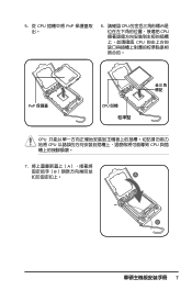
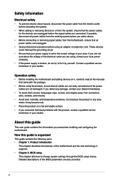
5. 從 CPU PnP 6. 請確認 CPU CPU CPU PnP 保護蓋 CPU CPU CPU CPU 7 A B A B
5. 從 CPU PnP 6. 請確認 CPU CPU CPU PnP 保護蓋 CPU CPU CPU CPU 7 A B A B
User Manual
Page 25
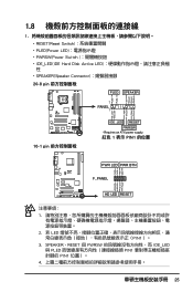
...-8 pin PLED SPEAKER 1 PANEL1 PLED+ PLED+5V Ground Ground Speaker P5B-E ® IDE_LED+ IDE_LED- PWR Ground Reset Ground 10-1 pin IDE_LED RESET PWRSW * Requires an ATX power supply. 紅色 1 表示 PIN1 的位置 PLED+ PLEDPWR GND IDELED+ IDELED- Ground Reset PWR LED PWR BTN M2N-X F_PANEL HD LED...
...-8 pin PLED SPEAKER 1 PANEL1 PLED+ PLED+5V Ground Ground Speaker P5B-E ® IDE_LED+ IDE_LED- PWR Ground Reset Ground 10-1 pin IDE_LED RESET PWRSW * Requires an ATX power supply. 紅色 1 表示 PIN1 的位置 PLED+ PLEDPWR GND IDELED+ IDELED- Ground Reset PWR LED PWR BTN M2N-X F_PANEL HD LED...
User Manual
Page 26
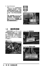
2. Asus Q-Connector 華碩 Q-Connector Q-Connector Q-Connector Q-Connector 1.9 24-pin 或 20-pin 24-pin 4-pin 的 ATX+12V 連接 ATX12V 24-pin ATX 20- pin ATX 26
2. Asus Q-Connector 華碩 Q-Connector Q-Connector Q-Connector Q-Connector 1.9 24-pin 或 20-pin 24-pin 4-pin 的 ATX+12V 連接 ATX12V 24-pin ATX 20- pin ATX 26

User Manual
Page 31
All rights reserved. BIOS 2.1 使用 AFUDOS BIOS AFUDOS DOS BIOS BIOS 程式。AFUDOS BIOS BIOS BIOS 程式 BIOS 程式。 1.2MB BIOS 1 AFUDOS 程式(afudos. done Write to file...... exe 2 DOS afudos /o[filename filename A:\>afudos /oOLDBIOS1.rom 3. 按下 afudos /oOLDBIOS1.rom AMI Firmware Update Utility - ok A:\> 當 BIOS DOS 31 Reading flash ..... Version 1.19(ASUS V2.07(03.11.24BB)) Copyright (C) 2002 American Megatrends, Inc.
All rights reserved. BIOS 2.1 使用 AFUDOS BIOS AFUDOS DOS BIOS BIOS 程式。AFUDOS BIOS BIOS BIOS 程式 BIOS 程式。 1.2MB BIOS 1 AFUDOS 程式(afudos. done Write to file...... exe 2 DOS afudos /o[filename filename A:\>afudos /oOLDBIOS1.rom 3. 按下 afudos /oOLDBIOS1.rom AMI Firmware Update Utility - ok A:\> 當 BIOS DOS 31 Reading flash ..... Version 1.19(ASUS V2.07(03.11.24BB)) Copyright (C) 2002 American Megatrends, Inc.

User Manual
Page 32
...03.11.24BB)) Copyright (C) 2002 American Megatrends, Inc. WARNING!! done Reading flash ...... Erasing flash ...... Version 1.19(ASUS V2.07(03.11.24BB)) Copyright (C) 2002 American Megatrends, Inc. All rights reserved. done Advance Check ...... done... DO.ROM AMI Firmware Update Utility - Erasing flash ...... WARNING!! 更新 BIOS 程式 AFUDOS BIOS 程式。 1 tw.asus.com BIOS 片中。 BIOS BIOS 2. 將 AFUDOS.EXE BIOS 3 DOS afudos /i[filename filename BIOS 程式。 A:\>afudos /...
...03.11.24BB)) Copyright (C) 2002 American Megatrends, Inc. WARNING!! done Reading flash ...... Erasing flash ...... Version 1.19(ASUS V2.07(03.11.24BB)) Copyright (C) 2002 American Megatrends, Inc. All rights reserved. done Advance Check ...... done... DO.ROM AMI Firmware Update Utility - Erasing flash ...... WARNING!! 更新 BIOS 程式 AFUDOS BIOS 程式。 1 tw.asus.com BIOS 片中。 BIOS BIOS 2. 將 AFUDOS.EXE BIOS 3 DOS afudos /i[filename filename BIOS 程式。 A:\>afudos /...

User Manual
Page 33
...20351;用 AwardBIOS Flash BIOS AwardBIOS Flash AwardBIOS Flash 程式(AWDFLASH.EXE BIOS AwardBIOS Flash BIOS 程式。 1 http://tw.asus.com BIOS M2N-VM HDMI.bin FAT 32/16 格式的 USB BIOS 2 CD/DVD AwardBIOS Flash BIOS 3 DOS 4. 當... A BIOS 檔案與 AwardBIOS Flash 5 A awdflash 並按下 鍵。 AwardBIOS Flash Utility for ASUS V1.14 (C) Phoenix Technologies Ltd. All Rights Reserved For C51PV-MCP51-M2A-VM HDMI-00 DATE:04/13/2006 Flash Type -
...20351;用 AwardBIOS Flash BIOS AwardBIOS Flash AwardBIOS Flash 程式(AWDFLASH.EXE BIOS AwardBIOS Flash BIOS 程式。 1 http://tw.asus.com BIOS M2N-VM HDMI.bin FAT 32/16 格式的 USB BIOS 2 CD/DVD AwardBIOS Flash BIOS 3 DOS 4. 當... A BIOS 檔案與 AwardBIOS Flash 5 A awdflash 並按下 鍵。 AwardBIOS Flash Utility for ASUS V1.14 (C) Phoenix Technologies Ltd. All Rights Reserved For C51PV-MCP51-M2A-VM HDMI-00 DATE:04/13/2006 Flash Type -

User Manual
Page 34
... OK No Update Write Fail Warning: Don't Turn Off Power Or Reset System! 在更新 BIOS 9 Flash Complete BIOS F1 AwardBIOS Flash Utility for ASUS V1.14 (C) Phoenix Technologies Ltd. PMC Pm49FL004T LPC/FWH File Name to Program: M2A-VM HDMI.bin Flashing Complete Press to Program: M2A-VM HDMI... Pm49FL004T LPC/FWH File Name to Continue Write OK F1 Reset No Update Write Fail 34 BIOS 7 BIOS N BIOS 8 BIOS BIOS AwardBIOS Flash Utility for ASUS V1.14 (C) Phoenix Technologies Ltd.
... OK No Update Write Fail Warning: Don't Turn Off Power Or Reset System! 在更新 BIOS 9 Flash Complete BIOS F1 AwardBIOS Flash Utility for ASUS V1.14 (C) Phoenix Technologies Ltd. PMC Pm49FL004T LPC/FWH File Name to Program: M2A-VM HDMI.bin Flashing Complete Press to Program: M2A-VM HDMI... Pm49FL004T LPC/FWH File Name to Continue Write OK F1 Reset No Update Write Fail 34 BIOS 7 BIOS N BIOS 8 BIOS BIOS AwardBIOS Flash Utility for ASUS V1.14 (C) Phoenix Technologies Ltd.

User Manual
Page 1
P5KPL-AM SE Motherboard
P5KPL-AM SE Motherboard

User Manual
Page 2
...and corporate names appearing in this manual, including the products and software described in any form or by any means, except documentation kept by ASUS; Product warranty or service will not be extended if: (1) the product is repaired, modified or altered, unless such repair, modification of their... OR INACCURACIES THAT MAY APPEAR IN THIS MANUAL, INCLUDING THE PRODUCTS AND SOFTWARE DESCRIBED IN IT. No part of ASUSTeK Computer Inc. ("ASUS"). ASUS PROVIDES THIS MANUAL "AS IS" WITHOUT WARRANTY OF ANY KIND, EITHER EXPRESS OR IMPLIED, INCLUDING BUT NOT LIMITED TO THE IMPLIED WARRANTIES ...
...and corporate names appearing in this manual, including the products and software described in any form or by any means, except documentation kept by ASUS; Product warranty or service will not be extended if: (1) the product is repaired, modified or altered, unless such repair, modification of their... OR INACCURACIES THAT MAY APPEAR IN THIS MANUAL, INCLUDING THE PRODUCTS AND SOFTWARE DESCRIBED IN IT. No part of ASUSTeK Computer Inc. ("ASUS"). ASUS PROVIDES THIS MANUAL "AS IS" WITHOUT WARRANTY OF ANY KIND, EITHER EXPRESS OR IMPLIED, INCLUDING BUT NOT LIMITED TO THE IMPLIED WARRANTIES ...
User Manual
Page 3
Contents Notices...v Safety information vi About this guide vi P5KPL-AM SE specifications summary viii Chapter 1: Product information 1.1 Before you proceed 1-1 1.2 Motherboard overview 1-2 1.2.1 Motherboard layout 1-2 1.2.2 Layout contents 1-2 1.3 Central Processing Unit (CPU 1-3 1.4 System memory 1-3 1.4.1 Overview 1-3 1.4.2 ... information 2.1 Managing and updating your BIOS 2-1 2.1.1 ASUS Update utility 2-1 2.1.2 ASUS EZ Flash 2 utility 2-2 2.1.3 ASUS CrashFree BIOS 3 utility 2-3 2.2 BIOS setup program 2-4 2.3 Main menu 2-4 2.3.1 System Time 2-4 2.3.2 System Date 2-4 iii
Contents Notices...v Safety information vi About this guide vi P5KPL-AM SE specifications summary viii Chapter 1: Product information 1.1 Before you proceed 1-1 1.2 Motherboard overview 1-2 1.2.1 Motherboard layout 1-2 1.2.2 Layout contents 1-2 1.3 Central Processing Unit (CPU 1-3 1.4 System memory 1-3 1.4.1 Overview 1-3 1.4.2 ... information 2.1 Managing and updating your BIOS 2-1 2.1.1 ASUS Update utility 2-1 2.1.2 ASUS EZ Flash 2 utility 2-2 2.1.3 ASUS CrashFree BIOS 3 utility 2-3 2.2 BIOS setup program 2-4 2.3 Main menu 2-4 2.3.1 System Time 2-4 2.3.2 System Date 2-4 iii

User Manual
Page 4
... APIC Support 2-11 2.5.4 APM Configuration 2-11 2.5.5 Hardware Monitor 2-12 2.6 Boot menu 2-13 2.6.1 Boot Device Priority 2-13 2.6.2 Boot Settings Configuration 2-13 2.6.3 Security 2-14 2.7 Tools menu 2-15 2.7.1 ASUS EZ Flash 2 2-15 2.7.2 AI NET 2 2-15 2.8 Exit menu 2-16 iv
... APIC Support 2-11 2.5.4 APM Configuration 2-11 2.5.5 Hardware Monitor 2-12 2.6 Boot menu 2-13 2.6.1 Boot Device Priority 2-13 2.6.2 Boot Settings Configuration 2-13 2.6.3 Security 2-14 2.7 Tools menu 2-15 2.7.1 ASUS EZ Flash 2 2-15 2.7.2 AI NET 2 2-15 2.8 Exit menu 2-16 iv

User Manual
Page 5
... Commission Statement This device complies with Part 15 of parts and recycling. This class B digital apparatus complies with Canadian ICES-003. DO NOT throw the motherboard in municipal waste. This symbol of shielded cables for radio noise emissions from that the battery should not be placed in municipal waste. Check local...
... Commission Statement This device complies with Part 15 of parts and recycling. This class B digital apparatus complies with Canadian ICES-003. DO NOT throw the motherboard in municipal waste. This symbol of shielded cables for radio noise emissions from that the battery should not be placed in municipal waste. Check local...
User Manual
Page 6
...this guide is organized This guide contains the following parts: • Chapter 1: Product introduction This chapter describes the features of the motherboard and the new technology it by yourself. Contact a qualified service technician or your dealer immediately. • To avoid short circuits...carefully read all power cables are not damaged. Detailed descriptions of the electrical outlet you need when installing and configuring the motherboard. vi Safety information Electrical safety • To prevent electric shock hazard, disconnect the power cable from the electric outlet ...
...this guide is organized This guide contains the following parts: • Chapter 1: Product introduction This chapter describes the features of the motherboard and the new technology it by yourself. Contact a qualified service technician or your dealer immediately. • To avoid short circuits...carefully read all power cables are not damaged. Detailed descriptions of the electrical outlet you need when installing and configuring the motherboard. vi Safety information Electrical safety • To prevent electric shock hazard, disconnect the power cable from the electric outlet ...

User Manual
Page 7
.... 1. Example: ++ Means that may include optional documentation, such as shown, then supply the required item or value enclosed in this manual. ASUS websites The ASUS website provides updated information on ASUS hardware and software products. 2. CAUTION: Information to prevent damage to the components when trying to the following symbols used in brackets. DANGER...
.... 1. Example: ++ Means that may include optional documentation, such as shown, then supply the required item or value enclosed in this manual. ASUS websites The ASUS website provides updated information on ASUS hardware and software products. 2. CAUTION: Information to prevent damage to the components when trying to the following symbols used in brackets. DANGER...
User Manual
Page 8
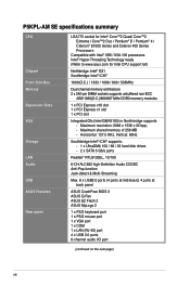
... high-Definition Audio CODEC Anti-Pop function Jack-detect & Multi-Streaming Max. 8 x USB2.0 ports (4 ports at mid-board, 4 ports at back panel ASUS CrashFree BIOS 3 ASUS Q-Fan ASUS EZ Flash 2 ASUS MyLogo 2 1 x PS/2 keyboard port 1 x PS/2 mouse port 1 x VGA port 1 x COM 1 x LAN (RJ-45) port 4 x...port (continued on the next page) viii Maximum resolution: 2048 x 1536 x 32 bpp, - P5KPL-AM SE specifications summary CPU Chipset Front Side Bus Memory Expansion Slots VGA Storage LAN Audio USB ASUS Features Rear panel LGA775 socket for Intel® Core™2 Quad/ Core™2 Extreme / Core...
... high-Definition Audio CODEC Anti-Pop function Jack-detect & Multi-Streaming Max. 8 x USB2.0 ports (4 ports at mid-board, 4 ports at back panel ASUS CrashFree BIOS 3 ASUS Q-Fan ASUS EZ Flash 2 ASUS MyLogo 2 1 x PS/2 keyboard port 1 x PS/2 mouse port 1 x VGA port 1 x COM 1 x LAN (RJ-45) port 4 x...port (continued on the next page) viii Maximum resolution: 2048 x 1536 x 32 bpp, - P5KPL-AM SE specifications summary CPU Chipset Front Side Bus Memory Expansion Slots VGA Storage LAN Audio USB ASUS Features Rear panel LGA775 socket for Intel® Core™2 Quad/ Core™2 Extreme / Core...
User Manual
Page 9
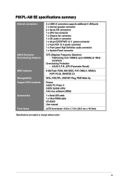
P5KPL-AM SE specifications summary Internal connectors ASUS Exclusive Overclocking Features BIOS features Manageability Support DVD contents Accessories Form factor 2 x USB 2.0 connectors supports additional 4 USB ports 1 x internal speaker connector 2 x ... Probe II ASUS Update utility Anti-virus software (OEM) 1 x Serial ATA cable 1 x Ultra ATA66 cable I/O shield User manual uATX form factor: 9.6 in x 7.2 in connector 1 x 24-pin EATXPWR 12 V power connector 1 x 4-pin ATX 12 V power connector 1 x Front panel High Definition audio connector 1 x System Panel connector SFS (Stepless Frequency ...
P5KPL-AM SE specifications summary Internal connectors ASUS Exclusive Overclocking Features BIOS features Manageability Support DVD contents Accessories Form factor 2 x USB 2.0 connectors supports additional 4 USB ports 1 x internal speaker connector 2 x ... Probe II ASUS Update utility Anti-virus software (OEM) 1 x Serial ATA cable 1 x Ultra ATA66 cable I/O shield User manual uATX form factor: 9.6 in x 7.2 in connector 1 x 24-pin EATXPWR 12 V power connector 1 x 4-pin ATX 12 V power connector 1 x Front panel High Definition audio connector 1 x System Panel connector SFS (Stepless Frequency ...
User Manual
Page 10
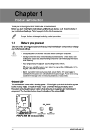
...indicate that the system is ON, in sleep mode, or in any motherboard component. SB_PWR P5KPL-AM SE ON Standy Power P5KPL-AM SE Onboard LED OFF Powered Off 1-1 ASUS P5KPL-AM SE Before you start installing the motherboard, and hardware devices on a grounded antistatic pad or in the bag that...list of the onboard LED. This is damaged or missing, contact your motherboard package. Onboard LED This motherboard comes with the component. • Before you install or remove any component, ensure that the ATX power supply is detached from the wall socket before touching any component. ...
...indicate that the system is ON, in sleep mode, or in any motherboard component. SB_PWR P5KPL-AM SE ON Standy Power P5KPL-AM SE Onboard LED OFF Powered Off 1-1 ASUS P5KPL-AM SE Before you start installing the motherboard, and hardware devices on a grounded antistatic pad or in the bag that...list of the onboard LED. This is damaged or missing, contact your motherboard package. Onboard LED This motherboard comes with the component. • Before you install or remove any component, ensure that the ATX power supply is detached from the wall socket before touching any component. ...
User Manual
Page 11
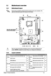
... the holes indicated by circles to secure the motherboard to the rear part of the chassis. 24.4cm(9.6in) Place this side towards the rear of the chassis. DO NOT overtighten the screws! ATX power connectors (24-pin EATXPWR, 4-pin ATX12V) 2. Internal speaker connector (4-pin SPEAKER)... PS2_USBPW1-4 USB34 EATXPWR LAN1_USB12 AUDIO RTL 8102EL CHA_FAN Intel® G31 PCIEX16 RTM870T-954 Super I/O Lithium Cell CMOS Power PCIEX1_1 P5KPL-AM SE SPEAKER Intel® ICH7 ALC662 AAFP F_PANEL CD PCI1 SB_PWR USBPW5-8 USB78 CLRTC USB56 PRI_IDE 8Mb BIOS SATA2 SATA1 Place six screws...
... the holes indicated by circles to secure the motherboard to the rear part of the chassis. 24.4cm(9.6in) Place this side towards the rear of the chassis. DO NOT overtighten the screws! ATX power connectors (24-pin EATXPWR, 4-pin ATX12V) 2. Internal speaker connector (4-pin SPEAKER)... PS2_USBPW1-4 USB34 EATXPWR LAN1_USB12 AUDIO RTL 8102EL CHA_FAN Intel® G31 PCIEX16 RTM870T-954 Super I/O Lithium Cell CMOS Power PCIEX1_1 P5KPL-AM SE SPEAKER Intel® ICH7 ALC662 AAFP F_PANEL CD PCI1 SB_PWR USBPW5-8 USB78 CLRTC USB56 PRI_IDE 8Mb BIOS SATA2 SATA1 Place six screws...
User Manual
Page 12
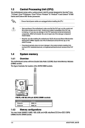
... A Channel B Sockets DIMM_A1 DIMM_B1 1.4.2 Memory configurations You may install 256MB, 512MB, 1GB, 2GB, and 4GB unbuffered ECC/non-ECC DDR2 DIMMs into the DIMM sockets. 1-3 ASUS P5KPL-AM SE ASUS will process Return Merchandise Authorization (RMA) requests only if the motherboard comes with two Double Data Rate 2 (DDR2) Dual Inline Memory Modules (DIMM) sockets.
... A Channel B Sockets DIMM_A1 DIMM_B1 1.4.2 Memory configurations You may install 256MB, 512MB, 1GB, 2GB, and 4GB unbuffered ECC/non-ECC DDR2 DIMMs into the DIMM sockets. 1-3 ASUS P5KPL-AM SE ASUS will process Return Merchandise Authorization (RMA) requests only if the motherboard comes with two Double Data Rate 2 (DDR2) Dual Inline Memory Modules (DIMM) sockets.
