User Manual
Page 3
......vi Safety information vii About this guide vii P5KPL-AM EPU specifications summary ix Chapter 1: Product introduction 1.1 Welcome 1-1 1.2 Package contents 1-1 1.3 Special features 1-1 1.3.1 Product highlights 1-1 1.3.2 Innovative ASUS features 1-2 1.4 Before you proceed 1-4 1.5 Motherboard overview 1-5 1.5.1 Placement direction 1-5 1.5.2 Screw holes 1-5 1.5.3 Motherboard layout 1-6 1.5.4 Layout contents 1-6 1.6 Central Processing Unit (CPU 1-7 1.6.1 Installing the CPU 1-7 1.6.2 Installing the CPU heatsink and fan 1-10 1.6.3 Uninstalling...
......vi Safety information vii About this guide vii P5KPL-AM EPU specifications summary ix Chapter 1: Product introduction 1.1 Welcome 1-1 1.2 Package contents 1-1 1.3 Special features 1-1 1.3.1 Product highlights 1-1 1.3.2 Innovative ASUS features 1-2 1.4 Before you proceed 1-4 1.5 Motherboard overview 1-5 1.5.1 Placement direction 1-5 1.5.2 Screw holes 1-5 1.5.3 Motherboard layout 1-6 1.5.4 Layout contents 1-6 1.6 Central Processing Unit (CPU 1-7 1.6.1 Installing the CPU 1-7 1.6.2 Installing the CPU heatsink and fan 1-10 1.6.3 Uninstalling...

User Manual
Page 4
... 1.10.1 Rear panel connectors 1-21 1.10.2 Internal connectors 1-22 1.11 Software support 1-28 1.11.1 Installing an operating system 1-28 1.11.2 Support DVD information 1-28 Chapter 2: BIOS information 2.1 Managing and updating your BIOS 2-1 2.1.1 ASUS Update utility 2-1 2.1.2 ASUS EZ Flash 2 utility 2-2 2.1.3 ASUS CrashFree BIOS 3 utility 2-3 2.2 BIOS setup program 2-4 2.2.1 BIOS menu screen 2-5 2.2.2 Menu bar 2-5 2.2.3 Navigation keys 2-6 2.2.4 Menu...
... 1.10.1 Rear panel connectors 1-21 1.10.2 Internal connectors 1-22 1.11 Software support 1-28 1.11.1 Installing an operating system 1-28 1.11.2 Support DVD information 1-28 Chapter 2: BIOS information 2.1 Managing and updating your BIOS 2-1 2.1.1 ASUS Update utility 2-1 2.1.2 ASUS EZ Flash 2 utility 2-2 2.1.3 ASUS CrashFree BIOS 3 utility 2-3 2.2 BIOS setup program 2-4 2.2.1 BIOS menu screen 2-5 2.2.2 Menu bar 2-5 2.2.3 Navigation keys 2-6 2.2.4 Menu...
User Manual
Page 6
...Evaluation, Authorisation, and Restriction of Chemicals) regulatory framework, we published the chemical substances in our products at ASUS REACH website at http://green.asus.com/english/REACH.htm. This symbol of the crossed out wheeled bin indicates that interference will not occur ...device must accept any interference received including interference that to which can radiate radio frequency energy and, if not installed and used in a particular installation. This equipment generates, uses and can be placed in the Radio Interference Regulations of the Canadian Department of ...
...Evaluation, Authorisation, and Restriction of Chemicals) regulatory framework, we published the chemical substances in our products at ASUS REACH website at http://green.asus.com/english/REACH.htm. This symbol of the crossed out wheeled bin indicates that interference will not occur ...device must accept any interference received including interference that to which can radiate radio frequency energy and, if not installed and used in a particular installation. This equipment generates, uses and can be placed in the Radio Interference Regulations of the Canadian Department of ...
User Manual
Page 7
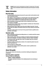
...of the motherboard and the new technology it by yourself. Contact a qualified service technician or your retailer. If you need when installing and configuring the motherboard. DO NOT throw the mercury-containing button cell battery in municipal waste. These devices could interrupt the grounding...it , carefully read all cables are correctly connected and the power cables are using an adpater or extension cord. Operation safety • Before installing the motherboard and adding devices on it may become wet. • Place the product on a stable surface. • If you add...
...of the motherboard and the new technology it by yourself. Contact a qualified service technician or your retailer. If you need when installing and configuring the motherboard. DO NOT throw the mercury-containing button cell battery in municipal waste. These devices could interrupt the grounding...it , carefully read all cables are correctly connected and the power cables are using an adpater or extension cord. Operation safety • Before installing the motherboard and adding devices on it may become wet. • Place the product on a stable surface. • If you add...
User Manual
Page 9
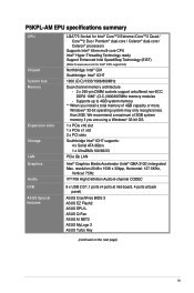
... (4 ports at mid-board, 4 ports at back panel) ASUS CrashFree BIOS 3 ASUS EZ Flash2 ASUS EPU-L ASUS Q-Fan ASUS AI NET2 ASUS MyLogo 2 ASUS Turbo Key (continued on the next page) ix We recommend a maximum of 3GB system memory if you install a total memory of 4GB capacity or more, Windows® ...32-bit operating system may only recognize less than 3GB. P5KPL-AM EPU...
... (4 ports at mid-board, 4 ports at back panel) ASUS CrashFree BIOS 3 ASUS EZ Flash2 ASUS EPU-L ASUS Q-Fan ASUS AI NET2 ASUS MyLogo 2 ASUS Turbo Key (continued on the next page) ix We recommend a maximum of 3GB system memory if you install a total memory of 4GB capacity or more, Windows® ...32-bit operating system may only recognize less than 3GB. P5KPL-AM EPU...
User Manual
Page 11
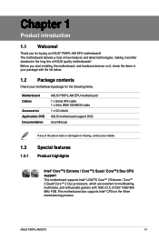
ASUS P5KPL-AM EPU 1-1 Thank you start installing the motherboard, and hardware devices on it another standout in the 45nm manufacturing process. This motherboard also supports Intel® CPUs in the long line ...; 2 Duo processors, which are excellent for multitasking, multimedia, and enthusiastic gamers with the list below. 1.2 Package contents Check your motherboard package for buying an ASUS® P5KPL-AM EPU motherboard! The motherboard delivers a host of new features and latest technologies, making it , check the items in your package with 1600 (O.C.)/1333/ 1066/ 800...
ASUS P5KPL-AM EPU 1-1 Thank you start installing the motherboard, and hardware devices on it another standout in the 45nm manufacturing process. This motherboard also supports Intel® CPUs in the long line ...; 2 Duo processors, which are excellent for multitasking, multimedia, and enthusiastic gamers with the list below. 1.2 Package contents Check your motherboard package for buying an ASUS® P5KPL-AM EPU motherboard! The motherboard delivers a host of new features and latest technologies, making it , check the items in your package with 1600 (O.C.)/1333/ 1066/ 800...

User Manual
Page 14
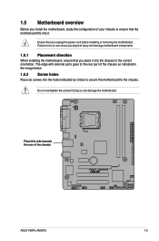
... Hold components by the edges to the motherboard, peripherals, or components. The illustration below shows the location of the following precautions before you install or remove any motherboard settings. • Unplug the power cord from the power supply. Onboard LED The motherboard comes with the component. &#...8226; Before you install motherboard components or change any component, ensure that the ATX power supply is switched off or the power cord is ON, in sleep...
... Hold components by the edges to the motherboard, peripherals, or components. The illustration below shows the location of the following precautions before you install or remove any motherboard settings. • Unplug the power cord from the power supply. Onboard LED The motherboard comes with the component. &#...8226; Before you install motherboard components or change any component, ensure that the ATX power supply is switched off or the power cord is ON, in sleep...
User Manual
Page 15
... can damage the motherboard. Doing so can cause you physical injury and damage motherboard components. 1.5.1 Placement direction When installing the motherboard, ensure that you install the motherboard, study the configuration of the chassis ASUS P5KPL-AM EPU 1-5 Ensure that the motherboard fits into the holes indicated by circles to secure the motherboard to ensure that...
... can damage the motherboard. Doing so can cause you physical injury and damage motherboard components. 1.5.1 Placement direction When installing the motherboard, ensure that you install the motherboard, study the configuration of the chassis ASUS P5KPL-AM EPU 1-5 Ensure that the motherboard fits into the holes indicated by circles to secure the motherboard to ensure that...
User Manual
Page 17
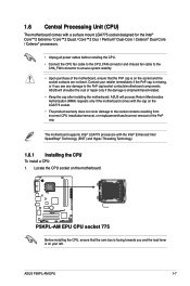
ASUS will shoulder the cost of repair only if the damage is shipment/transit-related. • Keep the cap after installing the motherboard. Before installing the CPU, ensure that the PnP cap is on the socket and the socket contacts are not bent. ... Intel® LGA775 processors with the Intel® Enhanced Intel SpeedStep® Technology (EIST) and Hyper-Threading Technology. 1.6.1 Installing the CPU To install a CPU: 1. ASUS P5KPL-AM EPU 1-7 ASUS will process Return Merchandise Authorization (RMA) requests only if the motherboard comes with the cap on the LGA775 socket. •...
ASUS will shoulder the cost of repair only if the damage is shipment/transit-related. • Keep the cap after installing the motherboard. Before installing the CPU, ensure that the PnP cap is on the socket and the socket contacts are not bent. ... Intel® LGA775 processors with the Intel® Enhanced Intel SpeedStep® Technology (EIST) and Hyper-Threading Technology. 1.6.1 Installing the CPU To install a CPU: 1. ASUS P5KPL-AM EPU 1-7 ASUS will process Return Merchandise Authorization (RMA) requests only if the motherboard comes with the cap on the LGA775 socket. •...

User Manual
Page 18
... from the load plate window to the left corner of the arrow to the socket pins, do not remove the PnP cap unless you are installing a CPU. 3. Retention tab A B Load lever PnP cap Load plate 4B 4A 3 5. Press the load lever with your thumb (A), then move it is released from the...
... from the load plate window to the left corner of the arrow to the socket pins, do not remove the PnP cap unless you are installing a CPU. 3. Retention tab A B Load lever PnP cap Load plate 4B 4A 3 5. Press the load lever with your thumb (A), then move it is released from the...

User Manual
Page 20
...heatsink and fan assembly, ensure that the four fasteners match the holes on top of CPU heatsink and fan assembly may differ, but the installation steps and functions should remain the same. Push down two fasteners at a time in a diagonal sequence to ensure optimum thermal condition and performance...fan. • Your Intel® LGA775 heatsink and fan assembly comes in place. The illustration above is closest to the chassis before you install the CPU fan and heatsink assembly. Place the heatsink on the motherboard. Ensure that the CPU fan cable is for reference only. 1-10...
...heatsink and fan assembly, ensure that the four fasteners match the holes on top of CPU heatsink and fan assembly may differ, but the installation steps and functions should remain the same. Push down two fasteners at a time in a diagonal sequence to ensure optimum thermal condition and performance...fan. • Your Intel® LGA775 heatsink and fan assembly comes in place. The illustration above is closest to the chassis before you install the CPU fan and heatsink assembly. Place the heatsink on the motherboard. Ensure that the CPU fan cable is for reference only. 1-10...
User Manual
Page 23
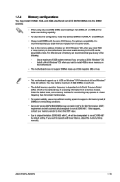
... run at DDR2-667 by default setting. For effective use a more memory on Windows® XP Professional x64 and Windows® Vista x64 editions. ASUS P5KPL-AM EPU 1-13 Install a 64-bit Windows® OS when you do any of 2GB DIMMs on each slot. • The default memory operation frequency is dependent on...
... run at DDR2-667 by default setting. For effective use a more memory on Windows® XP Professional x64 and Windows® Vista x64 editions. ASUS P5KPL-AM EPU 1-13 Install a 64-bit Windows® OS when you do any of 2GB DIMMs on each slot. • The default memory operation frequency is dependent on...
User Manual
Page 27
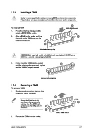
... retaining clips snap back in only one direction. Simultaneously press the retaining clips outward to both the motherboard and the components. ASUS P5KPL-AM EPU 1-17 Remove the DIMM from the socket. To install a DIMM: 1. Firmly insert the DIMM into a socket to unlock a DDR2 DIMM socket. 2. Failure to do so can cause severe damage...
... retaining clips snap back in only one direction. Simultaneously press the retaining clips outward to both the motherboard and the components. ASUS P5KPL-AM EPU 1-17 Remove the DIMM from the socket. To install a DIMM: 1. Firmly insert the DIMM into a socket to unlock a DDR2 DIMM socket. 2. Failure to do so can cause severe damage...
User Manual
Page 28
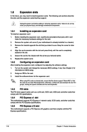
...need IRQ assignments. Align the card connector with the screw you intend to use . 4. Secure the card to the card. 3. Failure to install expansion cards. Install the software drivers for the card. 2. See Chapter 2 for later use . When using PCI cards on BIOS setup. 2. Remove the system ...change the necessary BIOS settings, if any. Assign an IRQ to the chassis with the slot and press firmly until the card is already installed in a chassis). 3. The following sub‑sections describe the slots and the expansion cards that complies with the PCI Express specifications. ...
...need IRQ assignments. Align the card connector with the screw you intend to use . 4. Secure the card to the card. 3. Failure to install expansion cards. Install the software drivers for the card. 2. See Chapter 2 for later use . When using PCI cards on BIOS setup. 2. Remove the system ...change the necessary BIOS settings, if any. Assign an IRQ to the chassis with the slot and press firmly until the card is already installed in a chassis). 3. The following sub‑sections describe the slots and the expansion cards that complies with the PCI Express specifications. ...
User Manual
Page 33
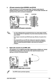
... version) and provides a minimum power of the system chassis. 2. Connect the S/PDIF Out module cable to this connector, then install the module to fit these connectors in only one orientation. ASUS P5KPL-AM EPU 1-23 The system may become unstable or may not boot up if the power is for ATX power supply plugs.... ATX power connectors (24-pin EATXPWR, 4-pin ATX12V) These connectors are designed to a slot opening at the back of 400 W. • Do not forget to install additional devices.
... version) and provides a minimum power of the system chassis. 2. Connect the S/PDIF Out module cable to this connector, then install the module to fit these connectors in only one orientation. ASUS P5KPL-AM EPU 1-23 The system may become unstable or may not boot up if the power is for ATX power supply plugs.... ATX power connectors (24-pin EATXPWR, 4-pin ATX12V) These connectors are designed to a slot opening at the back of 400 W. • Do not forget to install additional devices.

User Manual
Page 34
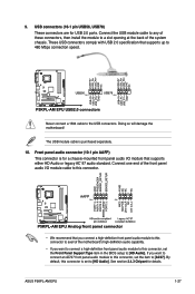
Optical drive audio connector (4-pin CD) This connector allows you to receive stereo audio input from sound sources such as a CD-ROM, TV tuner, or MPEG card. 1-24 Chapter 1: Product introduction Install the Windows® XP Service Pack 2 or later version before using Serial ATA. 5. Serial ATA connectors (7-pin SATA1-4) These connectors are for the Serial ATA signal cables for Serial ATA hard disk drives. 4.
Optical drive audio connector (4-pin CD) This connector allows you to receive stereo audio input from sound sources such as a CD-ROM, TV tuner, or MPEG card. 1-24 Chapter 1: Product introduction Install the Windows® XP Service Pack 2 or later version before using Serial ATA. 5. Serial ATA connectors (7-pin SATA1-4) These connectors are for the Serial ATA signal cables for Serial ATA hard disk drives. 4.
User Manual
Page 37
... HD Audio or legacy AC`97 audio standard. Never connect a 1394 cable to a slot opening at the back of these connectors, then install the module to the USB connectors. ASUS P5KPL-AM EPU 1-27 See section 2.4.3 Chipset for USB 2.0 ports. Doing so will damage the motherboard! USB connectors (10-1 pin USB56, USB78) These connectors...
... HD Audio or legacy AC`97 audio standard. Never connect a 1394 cable to a slot opening at the back of these connectors, then install the module to the USB connectors. ASUS P5KPL-AM EPU 1-27 See section 2.4.3 Chipset for USB 2.0 ports. Doing so will damage the motherboard! USB connectors (10-1 pin USB56, USB78) These connectors...

User Manual
Page 38
...vary. Refer to change at www.asus.com for reference only. Click an icon to display Support DVD/ motherboard information Click an item to the optical drive. Double-click the ASSETUP.EXE to run the Support DVD Place the Support DVD to install If Autorun is NOT enabled in this...the contents of the Support DVD to avail all motherboard features. Visit the ASUS website at any time without notice. The following screen is enabled in your OS documentation for detailed information. • Ensure that you can install to locate the file ASSETUP.EXE from the BIN folder. 1.11 Software ...
...vary. Refer to change at www.asus.com for reference only. Click an icon to display Support DVD/ motherboard information Click an item to the optical drive. Double-click the ASSETUP.EXE to run the Support DVD Place the Support DVD to install If Autorun is NOT enabled in this...the contents of the Support DVD to avail all motherboard features. Visit the ASUS website at any time without notice. The following screen is enabled in your OS documentation for detailed information. • Ensure that you can install to locate the file ASSETUP.EXE from the BIN folder. 1.11 Software ...
User Manual
Page 39
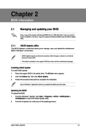
Installing ASUS Update To install ASUS Update: 1. Updating the BIOS To update the BIOS: 1. From the Windows® desktop, click Start > Programs > ASUS > ASUSUpdate > ASUSUpdate to complete the installation. Copy the original motherboard BIOS using this utility. Follow the onscreen instructions to launch the ASUS... updating your BIOS Save a copy of the updating process: ASUS P5KPL-AM EPU 2-1 Quit all Windows® applications before you update the BIOS using the ASUS Update utility. 2.1.1 ASUS Update utility The ASUS Update is available in the support DVD that allows you need...
Installing ASUS Update To install ASUS Update: 1. Updating the BIOS To update the BIOS: 1. From the Windows® desktop, click Start > Programs > ASUS > ASUSUpdate > ASUSUpdate to complete the installation. Copy the original motherboard BIOS using this utility. Follow the onscreen instructions to launch the ASUS... updating your BIOS Save a copy of the updating process: ASUS P5KPL-AM EPU 2-1 Quit all Windows® applications before you update the BIOS using the ASUS Update utility. 2.1.1 ASUS Update utility The ASUS Update is available in the support DVD that allows you need...
User Manual
Page 42
...ASUS website at www.asus.com. 2.2 BIOS setup program This motherboard supports a programmable Serial Peripheral Interface (SPI) chip that the computer can recognize these changes and record them in the future. This section explains how to configure your system using the navigation keys. 2-4 Chapter 2: BIOS information Even if you are installing... updating your selections from the available options using this program. We recommend to "Run Setup." Doing so can support ASUS CrashFree BIOS 3. The SPI chip on the system chassis. • Press the power button to use as easy to...
...ASUS website at www.asus.com. 2.2 BIOS setup program This motherboard supports a programmable Serial Peripheral Interface (SPI) chip that the computer can recognize these changes and record them in the future. This section explains how to configure your system using the navigation keys. 2-4 Chapter 2: BIOS information Even if you are installing... updating your selections from the available options using this program. We recommend to "Run Setup." Doing so can support ASUS CrashFree BIOS 3. The SPI chip on the system chassis. • Press the power button to use as easy to...


