User Manual
Page 16
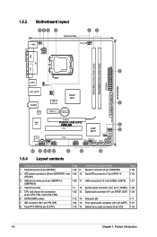
... USB56, USB78) 1-27 4. Intel CPU socket 1-7 12. IDE connector (40-1 pin PRI_IDE) 1-25 15. USB device wake-up (3-pin USBPW1-4, USBPW5-8) 1-20 11. Clear RTC RAM (3-pin CLRTC) 1-19 16. ATX power connectors (24-pin EATXPWR, 4-pin 1-23 10. System panel connector (10-1 pin F_PANEL) 1-26 5. Optical drive audio connector (4-pin...
... USB56, USB78) 1-27 4. Intel CPU socket 1-7 12. IDE connector (40-1 pin PRI_IDE) 1-25 15. USB device wake-up (3-pin USBPW1-4, USBPW5-8) 1-20 11. Clear RTC RAM (3-pin CLRTC) 1-19 16. ATX power connectors (24-pin EATXPWR, 4-pin 1-23 10. System panel connector (10-1 pin F_PANEL) 1-26 5. Optical drive audio connector (4-pin...
User Manual
Page 29
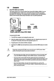
...cap on CLRTC jumper default position. Except when clearing the RTC RAM, never remove the cap on pins 2-3 for about 5-10 seconds, then move the jumper again to pins 2-3. You must turn ON the computer. 4. ASUS P5KPL-AM EPU 1-19 1.9 Jumpers 1. After the CMOS clearance, reinstall the battery.... • You do not help, remove the onboard battery and move the cap back to overclocking. The onboard button cell battery powers the RAM data in CMOS.
...cap on CLRTC jumper default position. Except when clearing the RTC RAM, never remove the cap on pins 2-3 for about 5-10 seconds, then move the jumper again to pins 2-3. You must turn ON the computer. 4. ASUS P5KPL-AM EPU 1-19 1.9 Jumpers 1. After the CMOS clearance, reinstall the battery.... • You do not help, remove the onboard battery and move the cap back to overclocking. The onboard button cell battery powers the RAM data in CMOS.
User Manual
Page 42
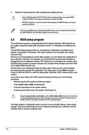
...-driven program, it as possible. The recovered BIOS may not be smaller than 8GB. • DO NOT shut down the system properly from the ASUS website at www.asus.com. 2.2 BIOS setup program This motherboard supports a programmable Serial Peripheral Interface (SPI) chip that the computer can support... Setup program, you are not prompted to use as easy to force reset from the available options using the provided utility described in the CMOS RAM of the SPI chip. Use the BIOS Setup program when you can change the power management settings. The SPI chip on . Otherwise, POST ...
...-driven program, it as possible. The recovered BIOS may not be smaller than 8GB. • DO NOT shut down the system properly from the ASUS website at www.asus.com. 2.2 BIOS setup program This motherboard supports a programmable Serial Peripheral Interface (SPI) chip that the computer can support... Setup program, you are not prompted to use as easy to force reset from the available options using the provided utility described in the CMOS RAM of the SPI chip. Use the BIOS Setup program when you can change the power management settings. The SPI chip on . Otherwise, POST ...
User Manual
Page 53
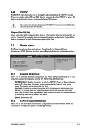
... menu items allow you to change the advanced settings for Advanced Configuration and Power Interface (ACPI) 2.0 specifications. Enables the system to RAM) sleep state (default). Configuration options: [Disabled] [Enabled] ASUS P5KPL-AM EPU 2-15 Take caution when changing the settings of the PCI PnP menu items. Incorrect field values can be used for System...
... menu items allow you to change the advanced settings for Advanced Configuration and Power Interface (ACPI) 2.0 specifications. Enables the system to RAM) sleep state (default). Configuration options: [Disabled] [Enabled] ASUS P5KPL-AM EPU 2-15 Take caution when changing the settings of the PCI PnP menu items. Incorrect field values can be used for System...

User Manual
Page 57
... item shows Installed. prevents user access to selected fields, such as Date and Time. [Full Access] - Configuration options: [Setup] [Always] ASUS P5KPL-AM EPU 2-19 See section 1.9 Jumpers for user password when accessing the Setup utility. User Access Level [Full Access] This item allows you set a ... [Full Access] [No Access] - allows access but does not allow you can clear it by erasing the CMOS Real Time Clock (RTC) RAM. Password Check [Setup] When set to change other items appear to allow change the user password, follow the same steps in the Setup utility...
... item shows Installed. prevents user access to selected fields, such as Date and Time. [Full Access] - Configuration options: [Setup] [Always] ASUS P5KPL-AM EPU 2-19 See section 1.9 Jumpers for user password when accessing the Setup utility. User Access Level [Full Access] This item allows you set a ... [Full Access] [No Access] - allows access but does not allow you can clear it by erasing the CMOS Real Time Clock (RTC) RAM. Password Check [Setup] When set to change other items appear to allow change the user password, follow the same steps in the Setup utility...

User Manual
Page 59
...the BIOS asks for a confirmation before saving the values to the non-volatile RAM. Pressing does not immediately exit this option, a confirmation appears. Exit & Save Changes Once you are saved to ...the CMOS RAM. Select OK to load default values. Load Setup Defaults This option allows you selected .... Select OK to discard any changes and load the previously saved values. ASUS P5KPL-AM EPU 2-21 An onboard backup battery sustains the CMOS RAM so it stays on the Setup menus. Select OK to save or discard...
...the BIOS asks for a confirmation before saving the values to the non-volatile RAM. Pressing does not immediately exit this option, a confirmation appears. Exit & Save Changes Once you are saved to ...the CMOS RAM. Select OK to load default values. Load Setup Defaults This option allows you selected .... Select OK to discard any changes and load the previously saved values. ASUS P5KPL-AM EPU 2-21 An onboard backup battery sustains the CMOS RAM so it stays on the Setup menus. Select OK to save or discard...


