
P5GPL English user's manual
Page 1
P5GPL Motherboard
P5GPL Motherboard

P5GPL English user's manual
Page 3
Contents Notices vi Safety information vii About this guide viii Typography ix P5GPL specifications summary x Chapter 1: Product introduction 1.1 Welcome 1-2 1.2 Package contents 1-2 1.3 Special features 1-3 1.3.1 Product highlights 1-3 1.3.2 ASUS Proactive features 1-5 1.3.3 Innovative ASUS features 1-5 1.4 Before you proceed 1-6 1.5 Motherboard overview 1-7 1.5.1 Placement direction 1-7 1.5.2 Screw holes 1-7 1.5.3 Motherboard layout 1-8 1.6 Central Processing Unit (CPU 1-9 1.6.1 Installling the CPU 1-9 2.3.2 Installling the CPU heatsink and fan 1-12...
Contents Notices vi Safety information vii About this guide viii Typography ix P5GPL specifications summary x Chapter 1: Product introduction 1.1 Welcome 1-2 1.2 Package contents 1-2 1.3 Special features 1-3 1.3.1 Product highlights 1-3 1.3.2 ASUS Proactive features 1-5 1.3.3 Innovative ASUS features 1-5 1.4 Before you proceed 1-6 1.5 Motherboard overview 1-7 1.5.1 Placement direction 1-7 1.5.2 Screw holes 1-7 1.5.3 Motherboard layout 1-8 1.6 Central Processing Unit (CPU 1-9 1.6.1 Installling the CPU 1-9 2.3.2 Installling the CPU heatsink and fan 1-12...

P5GPL English user's manual
Page 7
...are not sure about the voltage of the electrical outlet you add a device. • Before connecting or removing signal cables from the motherboard, ensure that came with the product, contact a qualified service technician or your dealer immediately. • To avoid short circuits, keep ... connected and the power cables are unplugged. • Seek professional assistance before you are connected. Operation safety • Before installing the motherboard and adding devices on a stable surface. • If you detect any damage, contact your retailer. vii If possible, disconnect all ...
...are not sure about the voltage of the electrical outlet you add a device. • Before connecting or removing signal cables from the motherboard, ensure that came with the product, contact a qualified service technician or your dealer immediately. • To avoid short circuits, keep ... connected and the power cables are unplugged. • Seek professional assistance before you are connected. Operation safety • Before installing the motherboard and adding devices on a stable surface. • If you detect any damage, contact your retailer. vii If possible, disconnect all ...

P5GPL English user's manual
Page 8
...warranty flyers, that you need when installing and configuring the motherboard. It includes description of the jumpers and connectors on ASUS hardware and software products. ASUS websites The ASUS website provides updated information on the motherboard. • Chapter 2: BIOS setup This chapter tells how ...standard package. Refer to the following parts: • Chapter 1: Product introduction This chapter describes the features of the motherboard and the new technology it supports. viii About this guide is organized This manual contains the following sources for additional ...
...warranty flyers, that you need when installing and configuring the motherboard. It includes description of the jumpers and connectors on ASUS hardware and software products. ASUS websites The ASUS website provides updated information on the motherboard. • Chapter 2: BIOS setup This chapter tells how ...standard package. Refer to the following parts: • Chapter 1: Product introduction This chapter describes the features of the motherboard and the new technology it supports. viii About this guide is organized This manual contains the following sources for additional ...

P5GPL English user's manual
Page 13
This chapter describes the motherboard features and the new technologies it supports. 1Product introduction ASUS P5GPL 1-1
This chapter describes the motherboard features and the new technologies it supports. 1Product introduction ASUS P5GPL 1-1

P5GPL English user's manual
Page 14
...following items. Motherboard ASUS P5GPL motherboard Cables 2 x Serial ATA signal cables 2 x Serial ATA power cables 1 x Ultra DMA/100 cables Floppy disk drive cable Accessories I/O shield A p p l i c a t i o n C D s ASUS motherboard support CD D o c u m e n t a t i o n User guide If any of ASUS quality motherboards! The motherboard delivers a ... line of the above items is damaged or missing, contact your motherboard package for buying an ASUS® P5GPL motherboard! Thank you start installing the motherboard, and hardware devices on it another standout in your package with the...
...following items. Motherboard ASUS P5GPL motherboard Cables 2 x Serial ATA signal cables 2 x Serial ATA power cables 1 x Ultra DMA/100 cables Floppy disk drive cable Accessories I/O shield A p p l i c a t i o n C D s ASUS motherboard support CD D o c u m e n t a t i o n User guide If any of ASUS quality motherboards! The motherboard delivers a ... line of the above items is damaged or missing, contact your motherboard package for buying an ASUS® P5GPL motherboard! Thank you start installing the motherboard, and hardware devices on it another standout in your package with the...

P5GPL English user's manual
Page 15
..., and PCI Express x16-lane port for a processor in packets. 1.3 Special features 1.3.1 Product highlights Latest processor technology The motherboard comes with Intel® 04B and 04A processors. This high speed interface is compliant to -point serial interconnections between devices and...speeds of system memory using DDR400/333 DIMMs. The ultra-fast 400MHz memory bus delivers the required bandwidth for details. ASUS P5GPL 1-3 The motherboard supports the Intel® Pentium® 4 processor with existing PCI specifications. Dual-channel DDR memory support Employing the ...
..., and PCI Express x16-lane port for a processor in packets. 1.3 Special features 1.3.1 Product highlights Latest processor technology The motherboard comes with Intel® 04B and 04A processors. This high speed interface is compliant to -point serial interconnections between devices and...speeds of system memory using DDR400/333 DIMMs. The ultra-fast 400MHz memory bus delivers the required bandwidth for details. ASUS P5GPL 1-3 The motherboard supports the Intel® Pentium® 4 processor with existing PCI specifications. Dual-channel DDR memory support Employing the ...

P5GPL English user's manual
Page 16
... the rear panel and at midboard. 8-channel high definition audio The motherboard supports 8-channel High Definition Audio through the S/PDIF interfaces on USB 2.0. S/PDIF digital sound ready The motherboard supports the S/PDIF Out function through the onboard ALC880 CODEC with digital...and 1-27 for details. Temperature, fan, and voltage monitoring The CPU temperature is backward compatible with USB 1.1. USB 2.0 technology The motherboard implements the Universal Serial Bus (USB) 2.0 specification, dramatically increasing the connection speed from the 12 Mbps bandwidth on USB 1.1 to...
... the rear panel and at midboard. 8-channel high definition audio The motherboard supports 8-channel High Definition Audio through the S/PDIF interfaces on USB 2.0. S/PDIF digital sound ready The motherboard supports the S/PDIF Out function through the onboard ALC880 CODEC with digital...and 1-27 for details. Temperature, fan, and voltage monitoring The CPU temperature is backward compatible with USB 1.1. USB 2.0 technology The motherboard implements the Universal Serial Bus (USB) 2.0 specification, dramatically increasing the connection speed from the 12 Mbps bandwidth on USB 1.1 to...
P5GPL English user's manual
Page 17
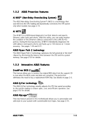
... that detects and reports Ethernet cable faults and shorts. ASUS P5GPL 1-5 See page 2-32 for details. 1.3.3 Innovative ASUS features CrashFree BIOS 2 This feature allows you to restore the original BIOS data from the support CD in the motherboard allows you can easily monitor the condition of the Intel... cable(s) and reports shorts and faults up to ensure quiet, cool, and efficient operation. See pages 1-26 and 2-21. ASUS Hyper Path 2 technology The ASUS Hyper Path 2 technology optimizes the full potential of the Ethernet cable(s) connected to the LAN (RJ-45) port(s). See page...
... that detects and reports Ethernet cable faults and shorts. ASUS P5GPL 1-5 See page 2-32 for details. 1.3.3 Innovative ASUS features CrashFree BIOS 2 This feature allows you to restore the original BIOS data from the support CD in the motherboard allows you can easily monitor the condition of the Intel... cable(s) and reports shorts and faults up to ensure quiet, cool, and efficient operation. See pages 1-26 and 2-21. ASUS Hyper Path 2 technology The ASUS Hyper Path 2 technology optimizes the full potential of the Ethernet cable(s) connected to the LAN (RJ-45) port(s). See page...

P5GPL English user's manual
Page 18
... mode. P5GPL P5GPL Onboard LED SB_PWR ON Standby Power OFF Powered Off 1-6 Chapter 1: Product introduction The illustration below shows the location of the following precautions before you install motherboard components or change any motherboard settings. ... a c h e d f r o m t h e p o w e r s u p p l y . Failure to do so may cause severe damage to indicate that you install or remove any motherboard component. Onboard LED The motherboard comes with the component. • Before you should shut down the system and unplug the power cable before removing or plugging in any...
... mode. P5GPL P5GPL Onboard LED SB_PWR ON Standby Power OFF Powered Off 1-6 Chapter 1: Product introduction The illustration below shows the location of the following precautions before you install motherboard components or change any motherboard settings. ... a c h e d f r o m t h e p o w e r s u p p l y . Failure to do so may cause severe damage to indicate that you install or remove any motherboard component. Onboard LED The motherboard comes with the component. • Before you should shut down the system and unplug the power cable before removing or plugging in any...

P5GPL English user's manual
Page 19
.... 1.5.1 Placement direction When installing the motherboard, make sure that you install the motherboard, study the configuration of your chassis to ensure that the motherboard fits into it into the holes indicated by circles to secure the motherboard to the chassis. Make sure to the rear part of the chassis P5GPL ASUS P5GPL 1-7 Do not overtighten the screws...
.... 1.5.1 Placement direction When installing the motherboard, make sure that you install the motherboard, study the configuration of your chassis to ensure that the motherboard fits into it into the holes indicated by circles to secure the motherboard to the chassis. Make sure to the rear part of the chassis P5GPL ASUS P5GPL 1-7 Do not overtighten the screws...

P5GPL English user's manual
Page 20
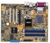
FLOPPY EATXPWR 30.5cm (12.0in) 1.5.3 Motherboard layout 24.5cm (9.6in) PS/2KBMS KBPWR T: Mouse B: Keyboard SPDIF_O ATX12V LGA775 Super I/O DDR DIMM_A1 (64 bit,184-pin module) DDR DIMM_A2 (64 bit,184-...: Side surround L/R Below:Bass Top:Line In Center:Line Out Below:Mic In Marvell 88E8053 USBPW12 USBPW34 PWR_FAN PCIEX1_1 Intel R 915PL CPU_FAN PCIEX16 PCI1 CD P5GPL PCI2 ALC880 SPDIF_OUT PCI3 AAFP PCIEX1_2 CR2032 3V Lithium Cell CMOS Power Intel® ICH6 SATA2 SATA4 SATA1 SATA3 PRI_IDE PCIEX1_3 USB56 USBPW56 USBPW78 CLRTC...
FLOPPY EATXPWR 30.5cm (12.0in) 1.5.3 Motherboard layout 24.5cm (9.6in) PS/2KBMS KBPWR T: Mouse B: Keyboard SPDIF_O ATX12V LGA775 Super I/O DDR DIMM_A1 (64 bit,184-pin module) DDR DIMM_A2 (64 bit,184-...: Side surround L/R Below:Bass Top:Line In Center:Line Out Below:Mic In Marvell 88E8053 USBPW12 USBPW34 PWR_FAN PCIEX1_1 Intel R 915PL CPU_FAN PCIEX16 PCI1 CD P5GPL PCI2 ALC880 SPDIF_OUT PCI3 AAFP PCIEX1_2 CR2032 3V Lithium Cell CMOS Power Intel® ICH6 SATA2 SATA4 SATA1 SATA3 PRI_IDE PCIEX1_3 USB56 USBPW56 USBPW78 CLRTC...

P5GPL English user's manual
Page 21
.... Locate the CPU socket on the LGA775 socket. • The product warranty does not cover damage to the PnP cap/socket pins/motherboard components. ASUS P5GPL 1-9 1.6 Central Processing Unit (CPU) The motherboard comes with a surface mount LGA775 socket designed for the Intel® Pentium® 4 processor in this section do not match the CPU...
.... Locate the CPU socket on the LGA775 socket. • The product warranty does not cover damage to the PnP cap/socket pins/motherboard components. ASUS P5GPL 1-9 1.6 Central Processing Unit (CPU) The motherboard comes with a surface mount LGA775 socket designed for the Intel® Pentium® 4 processor in this section do not match the CPU...

P5GPL English user's manual
Page 23
... a CPU that supports Hyper-Threading Technology. 2. Install an Intel® Pentium® 4 CPU that supports Hyper-Threading Technology. 3. ASUS P5GPL 1-11 B The CPU fits in the 775-land package with Hyper-Threading Technology. • Hyper-Threading Technology is supported under Windows&#... Hyper-Threading Technology, visit www.intel.com/info/hyperthreading. Notes on this motherboard: 1. Under Linux, use the Hyper-Threading Technology on Intel® Hyper-Threading Technology • This motherboard supports Intel® Pentium® 4 CPUs in only one correct orientation....
... a CPU that supports Hyper-Threading Technology. 2. Install an Intel® Pentium® 4 CPU that supports Hyper-Threading Technology. 3. ASUS P5GPL 1-11 B The CPU fits in the 775-land package with Hyper-Threading Technology. • Hyper-Threading Technology is supported under Windows&#... Hyper-Threading Technology, visit www.intel.com/info/hyperthreading. Notes on this motherboard: 1. Under Linux, use the Hyper-Threading Technology on Intel® Hyper-Threading Technology • This motherboard supports Intel® Pentium® 4 CPUs in only one correct orientation....

P5GPL English user's manual
Page 24
...making sure that a Thermal Interface Material is oriented as shown, with the narrow groove directed outward. 1-12 Chapter 1: Product introduction Fastener Motherboard hole Make sure each fastener is properly applied to the CPU heatsink or CPU before you install the CPU fan and heatsink assembly &#...before you install the heatsink and fan assembly. If you buy a CPU separately, make sure that the four fasteners match the holes on the motherboard. To install the CPU heatsink and fan: 1. 2.3.2 Installling the CPU heatsink and fan The Intel® Pentium® 4 LGA775 processor ...
...making sure that a Thermal Interface Material is oriented as shown, with the narrow groove directed outward. 1-12 Chapter 1: Product introduction Fastener Motherboard hole Make sure each fastener is properly applied to the CPU heatsink or CPU before you install the CPU fan and heatsink assembly &#...before you install the heatsink and fan assembly. If you buy a CPU separately, make sure that the four fasteners match the holes on the motherboard. To install the CPU heatsink and fan: 1. 2.3.2 Installling the CPU heatsink and fan The Intel® Pentium® 4 LGA775 processor ...

P5GPL English user's manual
Page 25
Push down two fasteners at a time in a diagonal sequence to secure the heatsink and fan B assembly in place, connect the CPU fan cable to the connector on the motherboard labeled CPU_FAN. ASUS P5GPL 1-13 When the fan and heatsink assembly is in place. A A A B B B A 3. Hardware monitoring errors can occur if you fail to connect the CPU fan connector! CPU_FAN GND P5GPL CPU FAN PWR CPU FAN IN CPU FAN PWM P5GPL CPU fan connector Do not forget to plug this connector. 2.
Push down two fasteners at a time in a diagonal sequence to secure the heatsink and fan B assembly in place, connect the CPU fan cable to the connector on the motherboard labeled CPU_FAN. ASUS P5GPL 1-13 When the fan and heatsink assembly is in place. A A A B B B A 3. Hardware monitoring errors can occur if you fail to connect the CPU fan connector! CPU_FAN GND P5GPL CPU FAN PWR CPU FAN IN CPU FAN PWM P5GPL CPU fan connector Do not forget to plug this connector. 2.

P5GPL English user's manual
Page 26
B A B B A 1-14 Chapter 1: Product introduction Pull up two fasteners at a time in a diagonal sequence to disengage the heatsink B and fan assembly from the connector on the motherboard labeled CPU_FAN. 2. Disconnect the CPU fan cable from the A A motherboard. 2.3.3 Uninstalling the CPU heatsink and fan To uninstall the CPU heatsink and fan: 1. Rotate each fastener counterclockwise. 3.
B A B B A 1-14 Chapter 1: Product introduction Pull up two fasteners at a time in a diagonal sequence to disengage the heatsink B and fan assembly from the connector on the motherboard labeled CPU_FAN. 2. Disconnect the CPU fan cable from the A A motherboard. 2.3.3 Uninstalling the CPU heatsink and fan To uninstall the CPU heatsink and fan: 1. Rotate each fastener counterclockwise. 3.

P5GPL English user's manual
Page 27
When reset, each fastener clockwise to reset the orientation. ASUS P5GPL 1-15 Rotate each fastener should be oriented as shown, with the narrow groove directed outward. Remove the heatsink and fan assembly from the motherboard. 5. 4.
When reset, each fastener clockwise to reset the orientation. ASUS P5GPL 1-15 Rotate each fastener should be oriented as shown, with the narrow groove directed outward. Remove the heatsink and fan assembly from the motherboard. 5. 4.

P5GPL English user's manual
Page 28
... may install 256 MB, 512 MB and 1 GB unbuffered non-ECC DDR DIMMs into the DIMM sockets using the memory configurations in this motherboard. 1-16 Chapter 1: Product introduction The following figure illustrates the location of 2GB total memory and two (2) ranks per memory channel only. ... compatibility, it is recommended that you obtain memory modules from the same vendor. • Due to chipset limitation, this motherboard supports a maximum of the sockets: P5GPL P5GPL 184-pin DDR DIMM sockets 1.7.2 Memory Configurations You may cause memory sizing error or system boot failure.
... may install 256 MB, 512 MB and 1 GB unbuffered non-ECC DDR DIMMs into the DIMM sockets using the memory configurations in this motherboard. 1-16 Chapter 1: Product introduction The following figure illustrates the location of 2GB total memory and two (2) ranks per memory channel only. ... compatibility, it is recommended that you obtain memory modules from the same vendor. • Due to chipset limitation, this motherboard supports a maximum of the sockets: P5GPL P5GPL 184-pin DDR DIMM sockets 1.7.2 Memory Configurations You may cause memory sizing error or system boot failure.

P5GPL English user's manual
Page 31
... out with your fingers when pressing the retaining clips. Remove the DIMM from the socket. ASUS P5GPL 1-19 Unlock a DIMM socket by pressing the retaining clips outward. 2. Locked Retaining Clip 1.7.4 Removing a DIMM Follow these steps to both the motherboard and the components. 1. Firmly insert the DIMM into a socket to unplug the power supply...
... out with your fingers when pressing the retaining clips. Remove the DIMM from the socket. ASUS P5GPL 1-19 Unlock a DIMM socket by pressing the retaining clips outward. 2. Locked Retaining Clip 1.7.4 Removing a DIMM Follow these steps to both the motherboard and the components. 1. Firmly insert the DIMM into a socket to unplug the power supply...


